AJAX Wireless alarm button, - Two-way communication, IP55, black
SKU: 367304817
€29,40€37,49
Unit price
DoubleButton User manual
DoubleButtonis a wireless hold-up device with advanced protection against accidental presses. The device communicates with a hub via the encryptedJewellerradio protocol and compatible only with Ajax system. The line-of-sight communication range is up to 1300 meters. DoubleButton operates from the pre-installed battery up to 5 years.
DoubleButton is connected and configured via Ajaxappson iOS, Android, macOS, and Windows. Push notifications, SMS, and calls can notify about alarms and events.
DoubleButtonis a wireless hold-up device, featuring two tight buttons and a plastic divider to protect against accidental presses. When pressed, it raises an alarm (hold-up event), transmitted to users and to the security company's monitoring station.
An alarm can be raised by pressing both buttons: one-time short or long press (more than 2 seconds). If only one of the buttons is pressed, the alarm signal is not transmitted.
All DoubleButton alarms are recorded in the Ajaxapp's notificationfeed. The short and long presses have different icons, but the event code sent to the monitoring station, SMS, and push notifications do not depend on the pressing manner.
DoubleButton can only operate as a hold-up device. Setting the type of alarm is not supported. Keep in mind that the device is active 24/7, so pressing the DoubleButton will raise an alarm regardless of the security mode.
The Ajax system can connect to the CMS and transmit alarms to the monitoring station in SurGard (Contact ID), ADEMCO 685, SIA (DC-09) and other proprietary protocols. A complete list of supported protocols is available at the link.
Connection
The device is not compatible withocBridge Plus, uartBridge, and third party security control panels.
Before starting connection
Install the Ajaxapp. Create anaccount. Add a hub to the app and create at least one room.
Check if your hub is on and connected to the Internet (via Ethernet cable, Wi-Fi, and/or mobile network). You can do this in the Ajax app or by looking at the Ajax logo on the front panel of the hub. The logo should light with white or green if the hub is connected to the network.
Check if the hub is not armed and does not update by reviewing its status in the app.
Only users with administrator permissions can connect a device to a hub.
How to connect DoubleButton to a hub
Open the Ajax app. If your account has access to several hubs, select the hub to which you want to connect the device.
Go to theDevicestab and clickAdd device.
Name the device, scan or enter the QRcode(located on the package), select a room and a group (if group mode is enabled).
ClickAdd - the countdown will begin.
Hold any of two buttons for 7 seconds. After adding DoubleButton, its LED will flash green once. DoubleButton will appear in the list of hub devices in the app.
To connect DoubleButton to a hub, it should be located on the same protected object as the system (within the hub's radio network range). If the connection fails, try again in 5 seconds.
DoubleButton can be connected to one hub only. When connected to a new hub, the device stops sending commands to the old hub. Added to a new hub, DoubleButton is not removed from the device list of the old hub. This must be done manually in the Ajax app.
Updating the device statuses in the list occurs only when DoubleButton is pressed and does not depend on the Jeweller settings.
States
The states screen contains information about the device and its current parameters. Find the DoubleButton states in the Ajax app:
Go to theDevicestab .
Select DoubleButton from the list.
Parameter
Value
Data import
Displays the error when transferring data to the new hub:
Failed- the device has not been transferred to the new hub.
Please note that after changing the settings, you need to pressBackto apply them.
Parameter
Value
Name
Device name. Displayed in the list of all hub devices, SMS, and notifications in the event feed.
The name can contain up to 12 Cyrillic characters or up to 24 Latin characters.
Room
Selecting the virtual room to which DoubleButton is assigned. The name of the room is displayed in SMS and notifications in the event feed.
LED brightness
Adjusting LED brightness:
Off - no indication.
Low.
Max.
Alert with a siren if button is pressed
When enabled, thesirensconnected to your security system signal about the button pressing. DoubleButton activates all sirens, regardless of the groups they are in.
User Guide
Opens the DoubleButton user manual.
Permanent Deactivation
Allows the user to disable the device without removing it from the system.Once deactivated, the device will not raise an alarm when pressed.
Disconnects DoubleButton from a hub and removes its settings.
Alarms
A DoubleButton alarm generates an event notification sent to the security company's monitoring station and system users. The pressing maner is indicated in the event feed of the app: for a short press, a single-arrow icon appears, and for a long press, the icon has two arrows.
To reduce the probability of false alarms, a security company can enable thealarm confirmationfeature.
Note that the alarm confirmation is a separate event that does not cancel the alarm transmission. Whether or not the feature is enabled, DoubleButton alarms are sent to a CMS and to security system users.
Indication
DoubleButton flashes red and green to indicate command execution and battery charge status.
Category
Indication
Event
Pairing with a security system
The whole frame flashes green 6 times.
The button is not connected to a security system.
The whole frame lights up green for a few seconds.
Connecting the device to a security system.
Command delivery indication
The frame part above the pressed button lights up green briefly.
One of the buttons is pressed and the command is delivered to a hub.
When only one button is pressed, DoubleButton does not raise an alarm.
The entire frame lights up green briefly after press.
Both buttons are pressed and the command is delivered to a hub.
The entire frame lights up red briefly after press.
One or both buttons were pressed and the command was not delivered to a hub.
Response Indication
(follows theCommand Delivery Indication)
The whole frame lights up green for half a second after the command delivery indication.
A hub received DoubleButton command and raised an alarm.
The whole frame lights up red for half a second after the command delivery indication.
A hub received DoubleButton command but did not raise an alarm.
Battery status indication
(followsFeedback Indication)
After the main indication, the entire frame lights up red and gradually goes out.
The battery replacement is required. DoubleButton commands are delivered to a hub.
Application
DoubleButton can be fixed on a surface or carried around.
How to fix DoubleButton on a surface
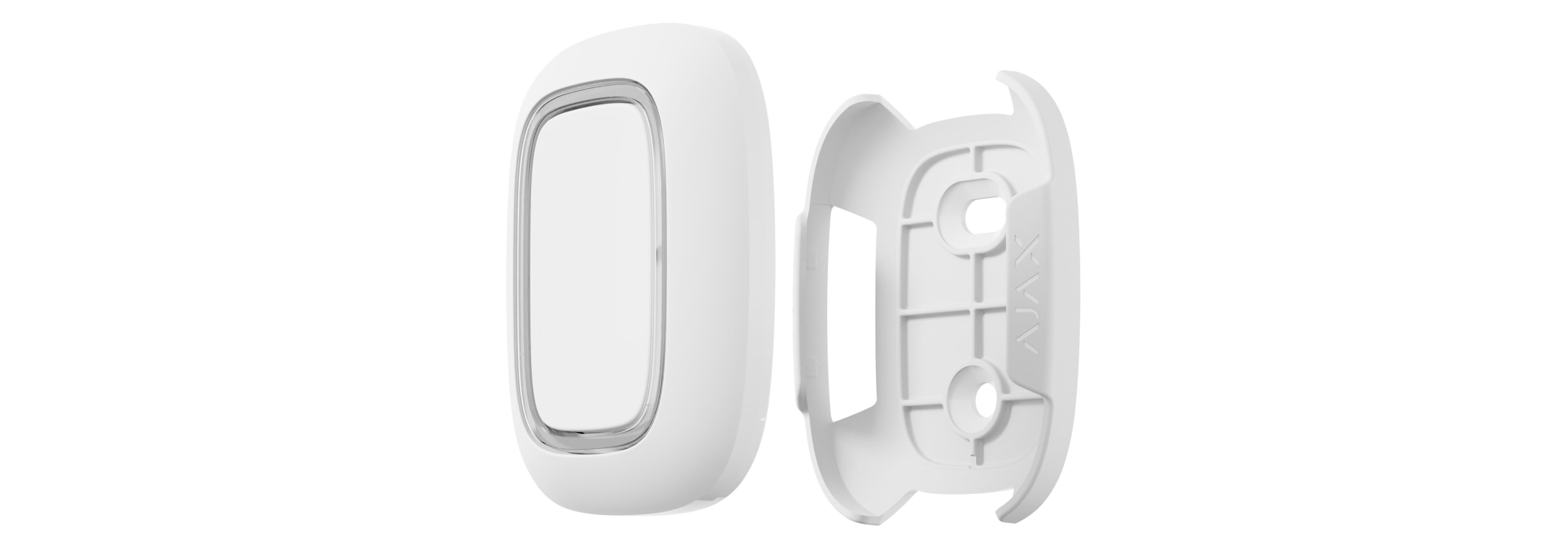
To fix the device on a surface (e. g. under a table), use Holder.
To install the device in the holder:
Choose a location to install the holder.
Press the button to test whether the commands are delivered to a hub. If not, choose another location or use aradio signal range extender.
When routing DoubleButton through a radio signal range extender, keep in mind that it does not automatically switch between a range extender and a hub. You can assign DoubleButton to a hub or another range extender in the Ajax app.
Fix Holder on the surface using the bundled screws or double-sided adhesive tape.
The button is easy to carry around thanks to a special hole on its body. It can be worn on the wrist or neck, or be hanged on a keyring.
DoubleButton has an IP55 protection index. Which means that the device body is protected from dust and splashes. And a special protective divider, tight buttons, and the need to press two buttons at once eliminate false alarms.
Using DoubleButton with alarm confirmation enabled
Alarm confirmationis a separate event that a hub generates and transmits to a CMS if the hold-up device has been activated by different types of pressing (short and long) or two specified DoubleButtons have transmitted alarms within a specified time. By responding to confirmed alarms only, a security company and police reduce the risk of unnecessary reacting.
Note that the alarm confirmation feature does not disable the alarm transmission. Whether or not the feature is enabled, DoubleButton alarms are sent to a CMS and to security system users.
To raise a confirmed alarm (hold-up event) with the same device, you need to perform any of these to actions:
Hold both buttons simultaneously for 2 seconds, release, and then press both buttons again briefly.
Simultaneously press both buttons briefly, release, and then hold both buttons for 2 seconds.
How to confirm alarm with several DoubleButtons
To raise a confirmed alarm (hold-up event), you can activate one hold-up device twice (according to the algorithm described above) or activate at least two different DoubleButtons. In this case, it doesn't matter in what way two different DoubleButtons were activated - with a short or long pressing.
Maintenance
When cleaning the device body, use products suitable for technical maintenance. Do not use substances containing alcohol, acetone, gasoline, or other active solvents to clean DoubleButton.
The pre-installed battery provides up to 5 years of operation, considering one pressing per day. More frequent use may decrease battery life. You can check the battery status at any time in the Ajax app.
Keep new and used batteries away from children. Do not ingest battery, Chemical Burn Hazard.
If DoubleButton cools down to -10°C and below, the battery charge indicator in the app can show low battery status until the button heats up to above-zero temperatures. Note that the battery charge level is not updated in the background, but only by pressing DoubleButton.
When the battery charge is low, users and a security company monitoring station receive notification. The device LED smoothly lights up red and goes out after each button pressing.
The warranty for the Limited Liability Company "Ajax Systems Manufacturing" products is valid for 2 years after purchase and does not extend to the bundled battery.
If the device does not function properly, we recommend that you first contact the support service as technical problems can be resolved remotely in half of the cases.
AJAX Wireless alarm button, - Two-way communication, IP55, white
SKU: 367304818
€29,40€37,49
Unit price
DoubleButton User manual
DoubleButtonis a wireless hold-up device with advanced protection against accidental presses. The device communicates with a hub via the encryptedJewellerradio protocol and compatible only with Ajax system. The line-of-sight communication range is up to 1300 meters. DoubleButton operates from the pre-installed battery up to 5 years.
DoubleButton is connected and configured via Ajaxappson iOS, Android, macOS, and Windows. Push notifications, SMS, and calls can notify about alarms and events.
DoubleButtonis a wireless hold-up device, featuring two tight buttons and a plastic divider to protect against accidental presses. When pressed, it raises an alarm (hold-up event), transmitted to users and to the security company's monitoring station.
An alarm can be raised by pressing both buttons: one-time short or long press (more than 2 seconds). If only one of the buttons is pressed, the alarm signal is not transmitted.
All DoubleButton alarms are recorded in the Ajaxapp's notificationfeed. The short and long presses have different icons, but the event code sent to the monitoring station, SMS, and push notifications do not depend on the pressing manner.
DoubleButton can only operate as a hold-up device. Setting the type of alarm is not supported. Keep in mind that the device is active 24/7, so pressing the DoubleButton will raise an alarm regardless of the security mode.
The Ajax system can connect to the CMS and transmit alarms to the monitoring station in SurGard (Contact ID), ADEMCO 685, SIA (DC-09) and other proprietary protocols. A complete list of supported protocols is available at the link.
Connection
The device is not compatible withocBridge Plus, uartBridge, and third party security control panels.
Before starting connection
Install the Ajaxapp. Create anaccount. Add a hub to the app and create at least one room.
Check if your hub is on and connected to the Internet (via Ethernet cable, Wi-Fi, and/or mobile network). You can do this in the Ajax app or by looking at the Ajax logo on the front panel of the hub. The logo should light with white or green if the hub is connected to the network.
Check if the hub is not armed and does not update by reviewing its status in the app.
Only users with administrator permissions can connect a device to a hub.
How to connect DoubleButton to a hub
Open the Ajax app. If your account has access to several hubs, select the hub to which you want to connect the device.
Go to theDevicestab and clickAdd device.
Name the device, scan or enter the QRcode(located on the package), select a room and a group (if group mode is enabled).
ClickAdd - the countdown will begin.
Hold any of two buttons for 7 seconds. After adding DoubleButton, its LED will flash green once. DoubleButton will appear in the list of hub devices in the app.
To connect DoubleButton to a hub, it should be located on the same protected object as the system (within the hub's radio network range). If the connection fails, try again in 5 seconds.
DoubleButton can be connected to one hub only. When connected to a new hub, the device stops sending commands to the old hub. Added to a new hub, DoubleButton is not removed from the device list of the old hub. This must be done manually in the Ajax app.
Updating the device statuses in the list occurs only when DoubleButton is pressed and does not depend on the Jeweller settings.
States
The states screen contains information about the device and its current parameters. Find the DoubleButton states in the Ajax app:
Go to theDevicestab .
Select DoubleButton from the list.
Parameter
Value
Data import
Displays the error when transferring data to the new hub:
Failed- the device has not been transferred to the new hub.
Please note that after changing the settings, you need to pressBackto apply them.
Parameter
Value
Name
Device name. Displayed in the list of all hub devices, SMS, and notifications in the event feed.
The name can contain up to 12 Cyrillic characters or up to 24 Latin characters.
Room
Selecting the virtual room to which DoubleButton is assigned. The name of the room is displayed in SMS and notifications in the event feed.
LED brightness
Adjusting LED brightness:
Off - no indication.
Low.
Max.
Alert with a siren if button is pressed
When enabled, thesirensconnected to your security system signal about the button pressing. DoubleButton activates all sirens, regardless of the groups they are in.
User Guide
Opens the DoubleButton user manual.
Permanent Deactivation
Allows the user to disable the device without removing it from the system.Once deactivated, the device will not raise an alarm when pressed.
Disconnects DoubleButton from a hub and removes its settings.
Alarms
A DoubleButton alarm generates an event notification sent to the security company's monitoring station and system users. The pressing maner is indicated in the event feed of the app: for a short press, a single-arrow icon appears, and for a long press, the icon has two arrows.
To reduce the probability of false alarms, a security company can enable thealarm confirmationfeature.
Note that the alarm confirmation is a separate event that does not cancel the alarm transmission. Whether or not the feature is enabled, DoubleButton alarms are sent to a CMS and to security system users.
Indication
DoubleButton flashes red and green to indicate command execution and battery charge status.
Category
Indication
Event
Pairing with a security system
The whole frame flashes green 6 times.
The button is not connected to a security system.
The whole frame lights up green for a few seconds.
Connecting the device to a security system.
Command delivery indication
The frame part above the pressed button lights up green briefly.
One of the buttons is pressed and the command is delivered to a hub.
When only one button is pressed, DoubleButton does not raise an alarm.
The entire frame lights up green briefly after press.
Both buttons are pressed and the command is delivered to a hub.
The entire frame lights up red briefly after press.
One or both buttons were pressed and the command was not delivered to a hub.
Response Indication
(follows theCommand Delivery Indication)
The whole frame lights up green for half a second after the command delivery indication.
A hub received DoubleButton command and raised an alarm.
The whole frame lights up red for half a second after the command delivery indication.
A hub received DoubleButton command but did not raise an alarm.
Battery status indication
(followsFeedback Indication)
After the main indication, the entire frame lights up red and gradually goes out.
The battery replacement is required. DoubleButton commands are delivered to a hub.
Application
DoubleButton can be fixed on a surface or carried around.
How to fix DoubleButton on a surface
To fix the device on a surface (e. g. under a table), use Holder.
To install the device in the holder:
Choose a location to install the holder.
Press the button to test whether the commands are delivered to a hub. If not, choose another location or use aradio signal range extender.
When routing DoubleButton through a radio signal range extender, keep in mind that it does not automatically switch between a range extender and a hub. You can assign DoubleButton to a hub or another range extender in the Ajax app.
Fix Holder on the surface using the bundled screws or double-sided adhesive tape.
The button is easy to carry around thanks to a special hole on its body. It can be worn on the wrist or neck, or be hanged on a keyring.
DoubleButton has an IP55 protection index. Which means that the device body is protected from dust and splashes. And a special protective divider, tight buttons, and the need to press two buttons at once eliminate false alarms.
Using DoubleButton with alarm confirmation enabled
Alarm confirmationis a separate event that a hub generates and transmits to a CMS if the hold-up device has been activated by different types of pressing (short and long) or two specified DoubleButtons have transmitted alarms within a specified time. By responding to confirmed alarms only, a security company and police reduce the risk of unnecessary reacting.
Note that the alarm confirmation feature does not disable the alarm transmission. Whether or not the feature is enabled, DoubleButton alarms are sent to a CMS and to security system users.
To raise a confirmed alarm (hold-up event) with the same device, you need to perform any of these to actions:
Hold both buttons simultaneously for 2 seconds, release, and then press both buttons again briefly.
Simultaneously press both buttons briefly, release, and then hold both buttons for 2 seconds.
How to confirm alarm with several DoubleButtons
To raise a confirmed alarm (hold-up event), you can activate one hold-up device twice (according to the algorithm described above) or activate at least two different DoubleButtons. In this case, it doesn't matter in what way two different DoubleButtons were activated - with a short or long pressing.
Maintenance
When cleaning the device body, use products suitable for technical maintenance. Do not use substances containing alcohol, acetone, gasoline, or other active solvents to clean DoubleButton.
The pre-installed battery provides up to 5 years of operation, considering one pressing per day. More frequent use may decrease battery life. You can check the battery status at any time in the Ajax app.
Keep new and used batteries away from children. Do not ingest battery, Chemical Burn Hazard.
If DoubleButton cools down to -10°C and below, the battery charge indicator in the app can show low battery status until the button heats up to above-zero temperatures. Note that the battery charge level is not updated in the background, but only by pressing DoubleButton.
When the battery charge is low, users and a security company monitoring station receive notification. The device LED smoothly lights up red and goes out after each button pressing.
The warranty for the Limited Liability Company "Ajax Systems Manufacturing" products is valid for 2 years after purchase and does not extend to the bundled battery.
If the device does not function properly, we recommend that you first contact the support service as technical problems can be resolved remotely in half of the cases.
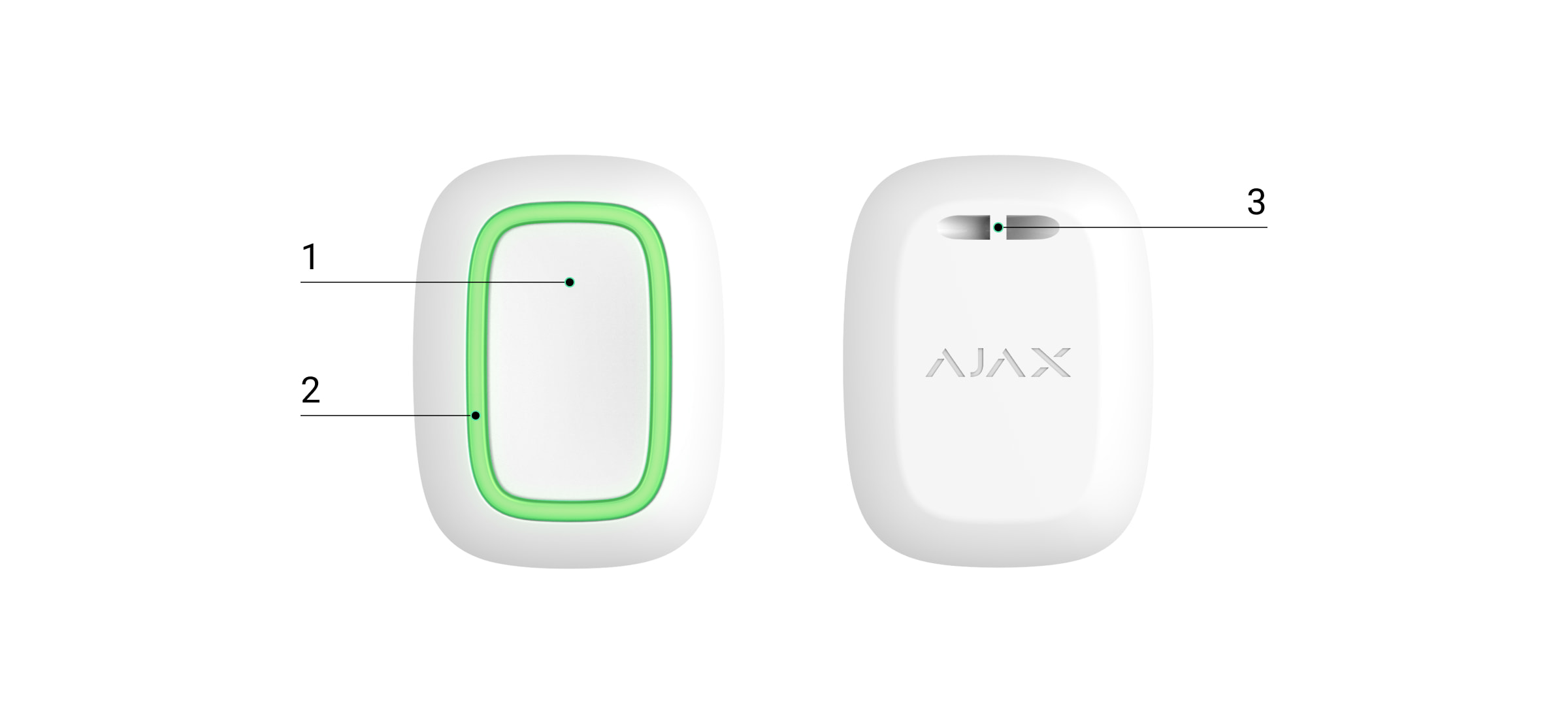
Buttonis a wireless panic button with protection against accidental press and additional mode to controlautomation devices.
Button is compatible with Ajaxhubsonly. No support forocBridge Plusand uartBridgeintegration modules!
Button is connected to the security system and configured via Ajaxappson iOS, Android, macOS, and Windows. The users are alerted of all alarms and events via push notifications, SMS, and phone calls (if enabled).
Buttonis a wireless panic button that, when pressed, transmits an alarm to users, as well as to the security company's CMS. In Control mode, Button allows you to control Ajax automation devices with a short or long press of a button.
In panic mode, the Button can operate as a panic button and signal about a threat, or notify of the need for auxiliary help, or inform about the intrusion, fire, gas alarm, or leakage. You can select the type of alarm in the button settings. The text of alarm notifications depends on the selected type, as well as the event codes transmitted to the central monitoring station of the security company (CMS).
In the Buttonsettings-Scenariosmenu, you can assign the action of an automation device(Relay,WallSwitchorSocket) to a button press.
The Button is equipped with protection against accidental press and transmits alarms at a distance of up to 1,300 m from the hub. Please be aware that the presence of any obstructions that impede the signal (for example, walls or floors) will reduce this distance.
Button is easy to carry around. You can always keep it on a wrist or a necklace. The device is resistant to dust and splashes.
When connecting Button viaradio signal range extender, please note that Button does not automatically switch between the radio networks of the radio signal extender and the hub. You can manually assign Button to another hub or range extender in the app.
Button has theBattery charge auto-checkoption. When enabled, the system once a day checks the battery state of the button. If the auto-check is disabled, the battery state updates only when the device is pressed.
The feature is available for buttons with firmware version 6.60.0.13 and later. When added to a hub with OS Malevich version 2.17 and later (except Hub (2G) Jeweller and Hub (4G) Jeweller).
Open the Ajaxappand select thespacewhere you want to add the button.
Go to theDevices tab and clickAdd device.
Name the device, scan its QR code (located on the package) or enter it manually, select a room and a group (ifgroup modeis enabled).
ClickAddand the countdown will begin.
Hold the button for 7 seconds. When the Button is added, the LEDs will flash green once.
For detection and pairing, the Button must be located within the hub radio communication zone (on the single protected object).
The connected button will appear in the list of hub devices in the application. Updating the statuses of the device in the list does not depend on the polling time value in the hub settings. Data is updated only by pressing the Button.
The Button only works with one hub. When connected to a new hub, the button Button stops transmitting commands to the old hub. Note that after being added to the new hub, the Button is not automatically removed from the device list of the old hub. This must be done manually through the Ajax application.
States
Button states can be found in the Ajax app:
Ajax app→Devices →Button
Parameter
Value
Data import
Displays the error when transferring data to the new hub:
Failed- the device has not been transferred to the new hub.
Battery level of the device. Two states available:
OK.
Battery discharged.
You can check the battery charge by clicking on the icon (displayed when theBattery Charge Auto-Checkoption is enabled).
The feature is available for buttons with firmware version 6.60.0.13 and later. When added to a hub with OS Malevich version 2.17 and later (except Hub (2G) Jeweller and Hub (4G) Jeweller).
Displays the device's status: active or completely disabled by the user.
Firmware
Button firmware version.
Device ID
Device identifier. Also available on the device's board and its package.
Device No.
Number of the device loop (zone).
Settings
You can adjust the device parameters in the settings section:
Ajax app→ Devices →Button→Settings
Parameter
Value
Name
Name of the device, can be changed.
Room
The choice of the virtual room that the device is assigned to.
Battery charge auto-check
If the toggle is enabled, the system checks the battery state of the device once a day. If the auto-check is disabled, the battery state updates only when the device is pressed.
The feature is available for buttons with firmware version 6.60.0.13 and later. When added to a hub with OS Malevich version 2.17 and later (except Hub (2G) Jeweller and Hub (4G) Jeweller).
Notify if the device was unreachable for 3 days
When the toggle is enabled, the user receives a corresponding notification if the button has not communicated with the hub for three days. The setting is available when theBattery charge auto-checktoggle is enabled.
Operating mode
Displays the operating mode of the button. Three modes are available:
Panic- sends an alarm when pressed.
Control- controls automation devices by short or long (3 sec) pressing.
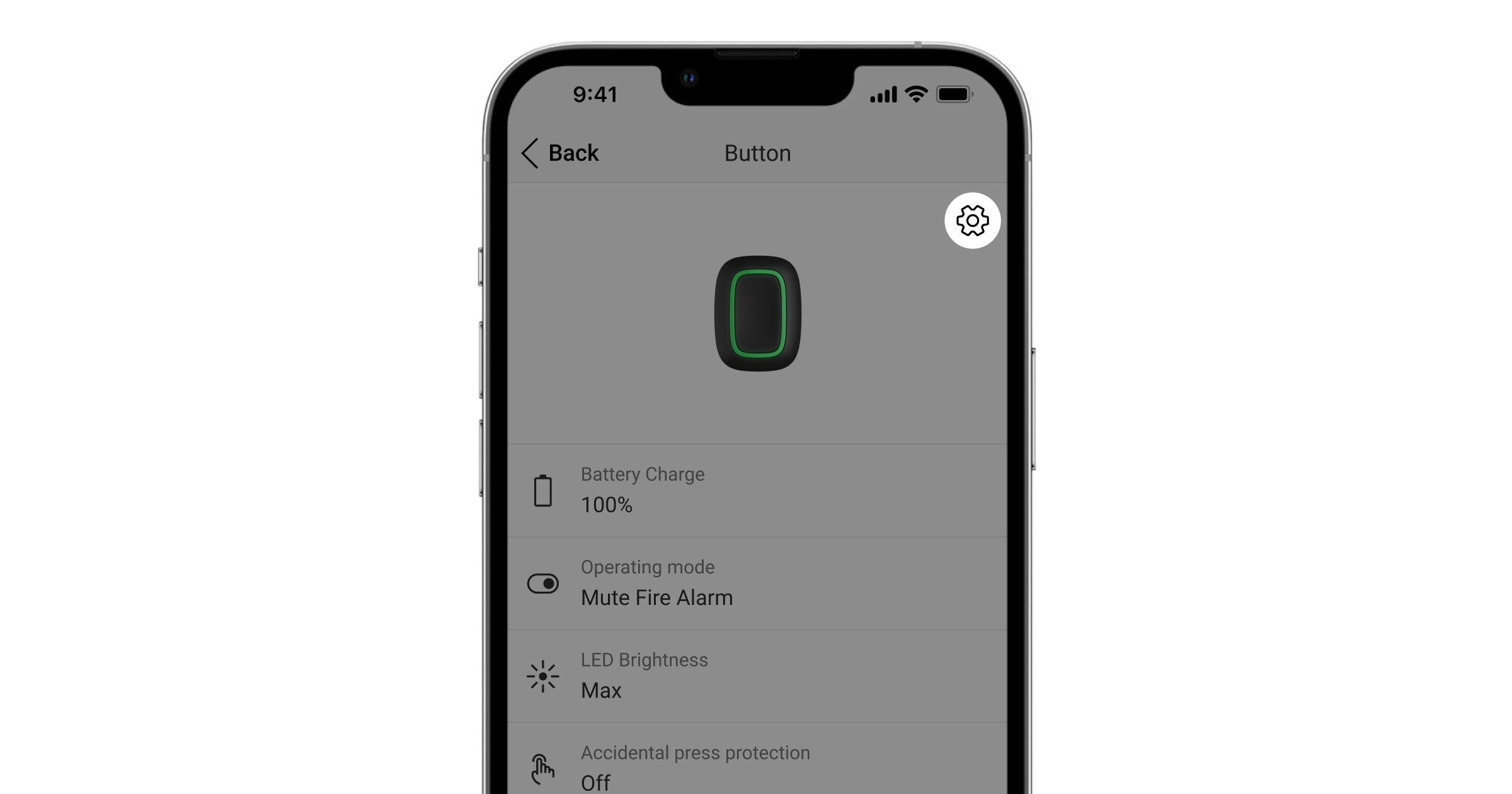
Mute Fire Alarm- when pressed, mutes the alarm of Ajax fire detectors. The option is available ifInterconnected Fire Alarmfeature is enabled.
The text of SMS and notifications in the app depends on the selected type of alarm.
LED brightness
This displays the current brightness of the indicator lights:
Disabled (LED indication is disabled).
Low.
Max.
Accidental press protection
(displayed only forPanicand MuteFire Alarmoperating modes)
Displays the selected type of protection against accidental activation:
Off- protection disabled.
Long press- in order to send an alarm, you need to press and hold the button for more than 1.5 seconds.
Double press- in order to send an alarm, you need to double-press the button with a pause of no more than 0.5 seconds between the presses.
Alert with a siren if button is pressed
If the toggle is enabled, pressing a panic button activates Ajaxsirensconnected to the system. Ajax Button activates all sirens, regardless of the groups they are in.
Scenarios
Opens the menu for creating and configuring scenarios.
Battery state check
Opens the menu for the battery charge checking.
The feature is available for buttons with firmware version 6.60.0.13 and later. When added to a hub with OS Malevich version 2.17 and later (except Hub (2G) Jeweller and Hub (4G) Jeweller).
User guide
Opens Button User manual.
Permanent deactivation
Allows a user to deactivate the device without deleting it from the system.
Once deactivated, the device will no longer execute system commands and participate in automation scenarios. Additionally, the panic button of a deactivated device will be disabled.
Disconnects Button from the hub and deletes its settings.
Operating indication
Button status is indicated with red or green LED indicators.
Category
Indication
Event
Adding or removing from the hub. Changing the battery
Green LEDs flash 3 times.
The button is not added to any hub.
The indication is available for buttons with firmware version 6.60.X.X and later.
Green LEDs flash 6 times.
The button is removed from the hub, or the battery is changed.
The indication is available for buttons with firmware version 6.60.X.X and later. For newer firmware versions, this indication means that the button is not added to any hub.
Lights up green for a few seconds.
Adding the button to the hub.
Command delivery indication
Lights up green briefly.
Command is delivered to the hub.
Lights up red briefly.
Command is not delivered to the hub.
Long press indication in Control mode
Flashes green briefly.
Button recognised the pressing as a long press and sent the corresponding command to the hub.
Feedback Indication
(follows theCommand Delivery Indication)
Lights up green for about half a second after the command delivery indication.
The hub has received and performed the command.
Briefly lights up red after the command delivery indication.
The hub did not perform the command.
Battery status
(followsFeedback Indication)
After the main indication it lights up red and goes out smoothly.
Button battery needs to be replaced. At the same time, button commands are delivered to the hub.
In the panic button mode, Button can call security or help, as well as alert of an emergency by activating sirens and sending other users a notification in the app. In the Button settings, you can select one type of alarm out of eight:
Intrusion
Fire
Auxiliary alarm
Panic button
Gas alarm
Malfunction
Leakage
Custom (not sent to the security company monitoring station)
The type of alarm determines the event code sent to the security company monitoring station (CMS) and the notification text received by the user. This ensures the accurate response to the threat.
Note that inPanic Mode, pressing the Button will raise an alarm regardless of the system security mode.
If Button is pressed, an alarm can alsorun a scenarioin the Ajax system.
Button can be installed on a flat surface or carried around. To install on a flat surface (for example, under the table), secure the Button with double-sided adhesive tape. To carry the Button on the strap: attach the strap to the Button using the mounting hole in the main body of the Button.
Control Mode
Button can be used to control the automation devices. InControl mode, the Button has two pressing options: short and long (the button is pressed for more than 3 seconds). These pressings can trigger the execution of an action by one or more automation devices: Relay, WallSwitch, or Socket.
To bind an automation device action to a long or short press of a Button:
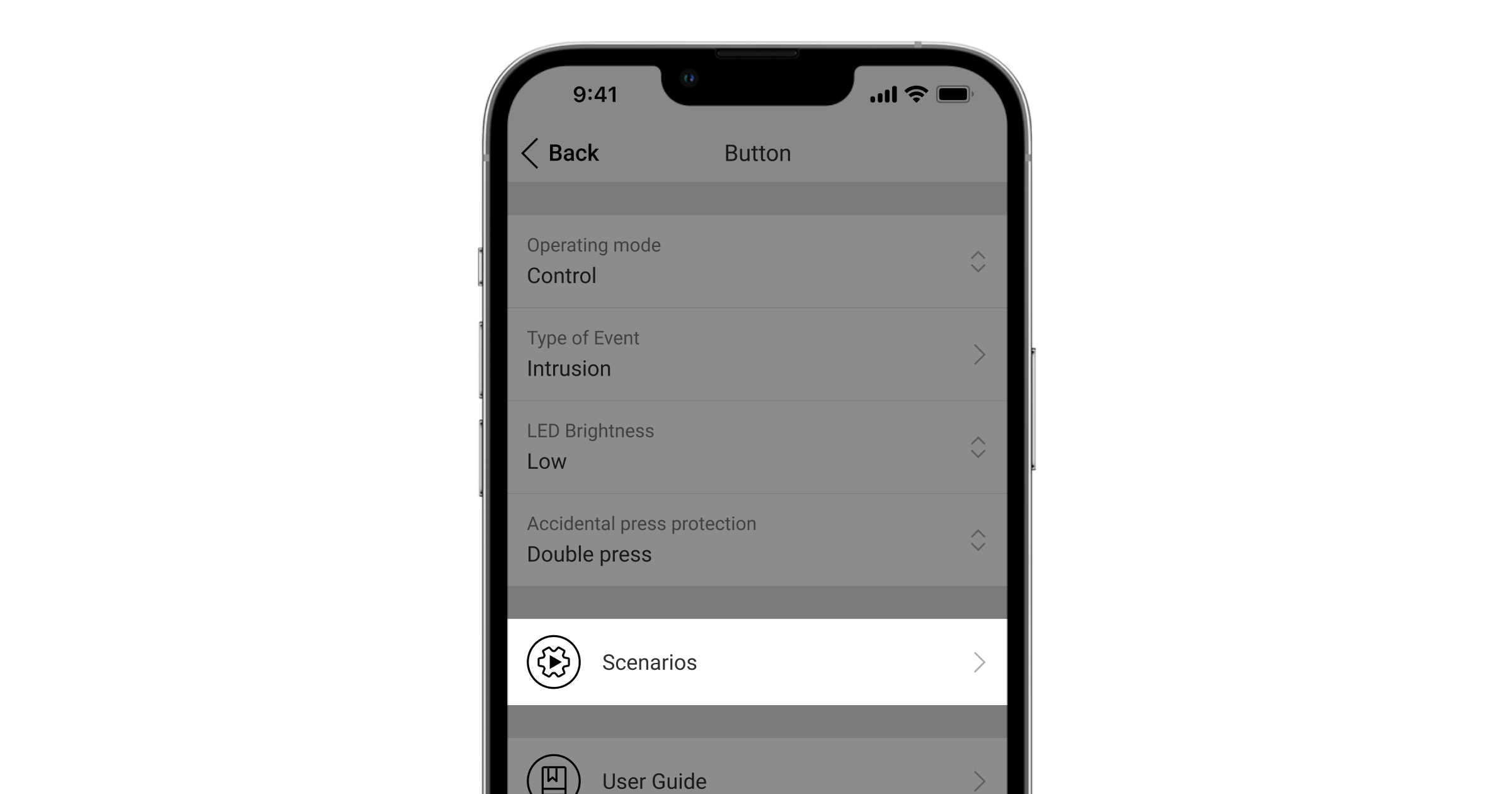
SelectButtonin the list of devices and go to settings by clicking the gear icon .
Select theControlmode in theOperation mode section. Click on the actualButtondevice to save the changes
Go to theScenariosmenu. ClickCreate Scenarioif you are creating a scenario for the first time, orAdd Scenarioif scenarios have already been created in the security system.
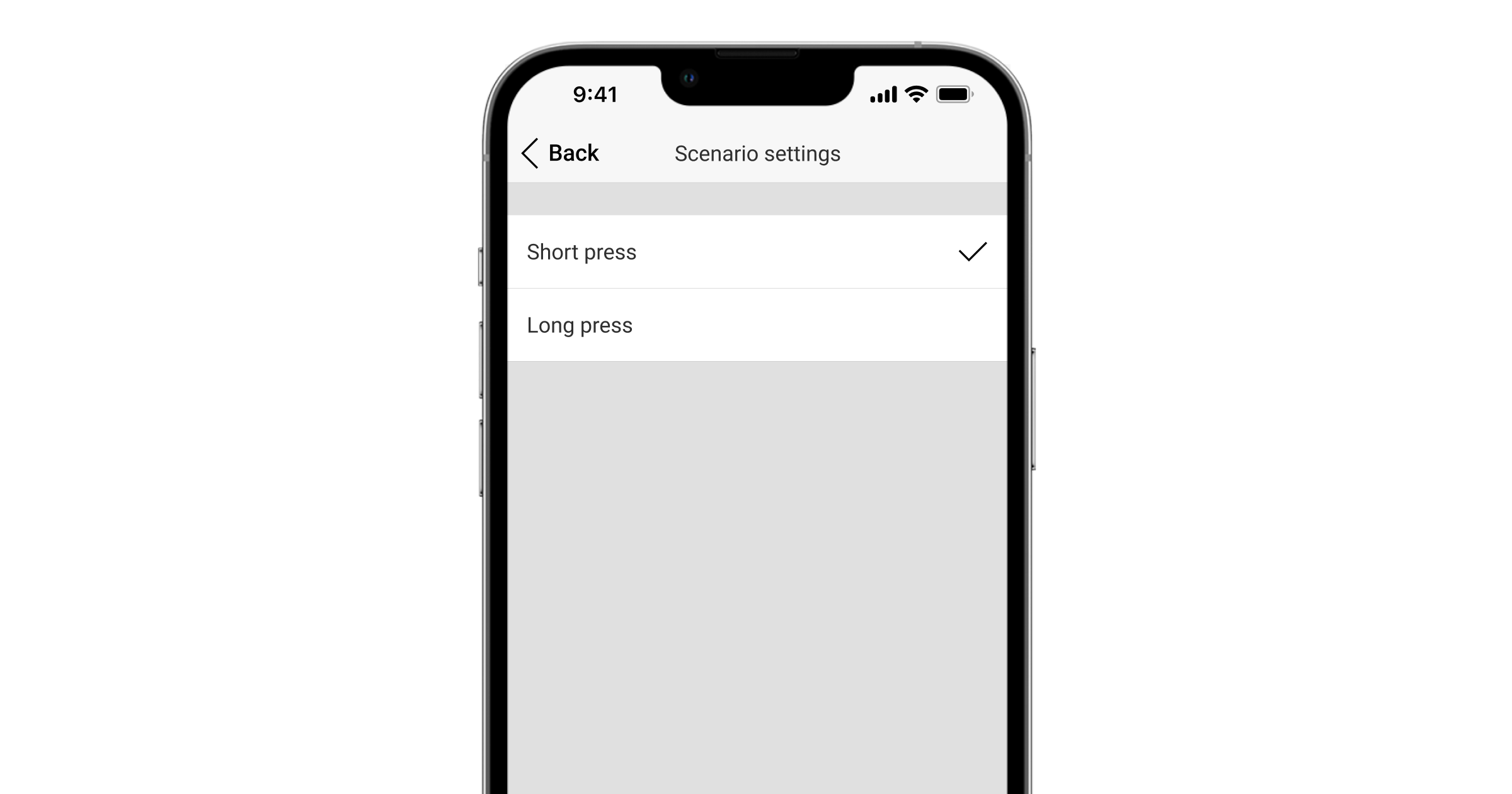
Select a pressing option to run the scenario:Short pressorLong press.
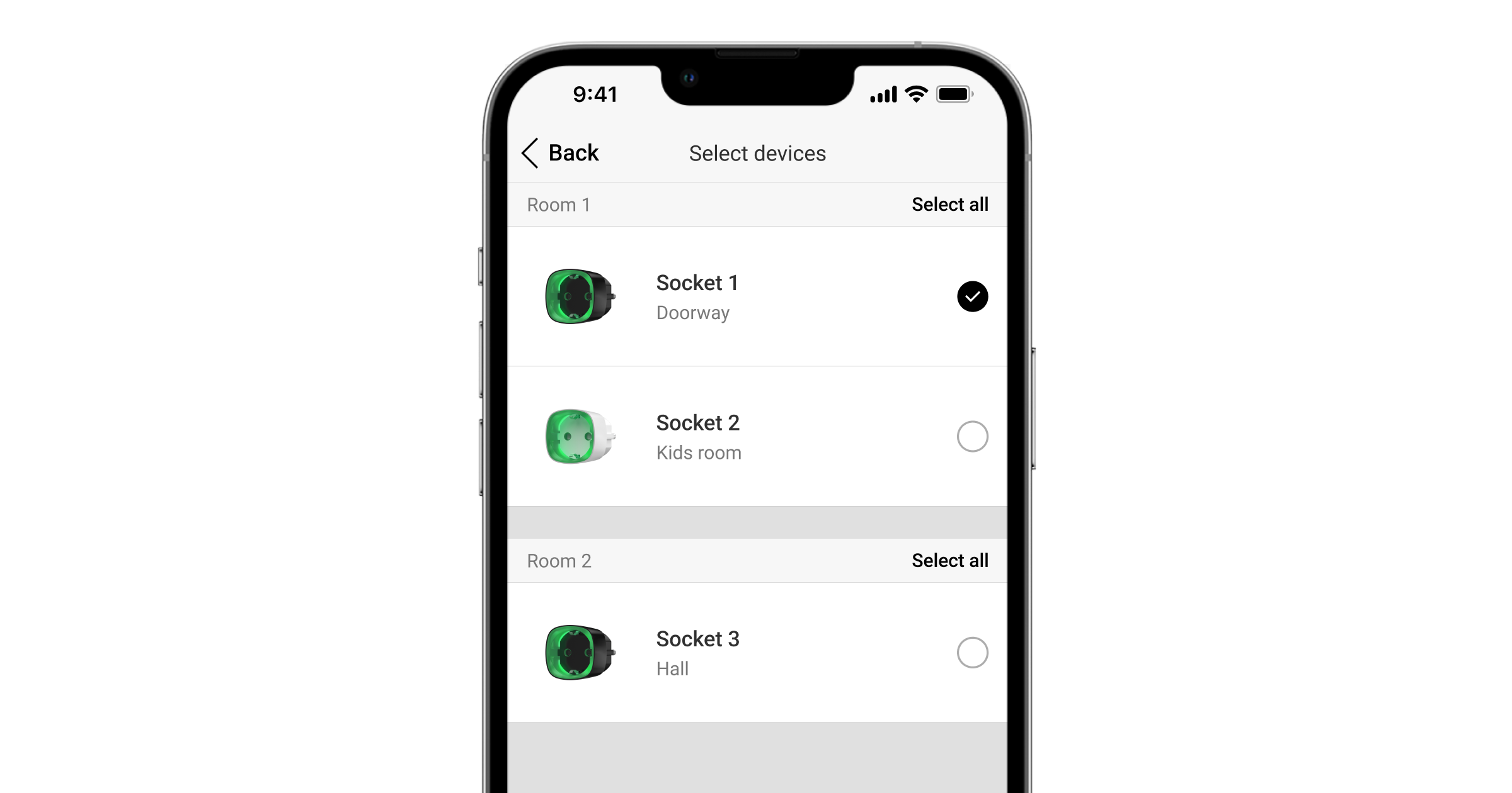
Select the automation device to execute the action.
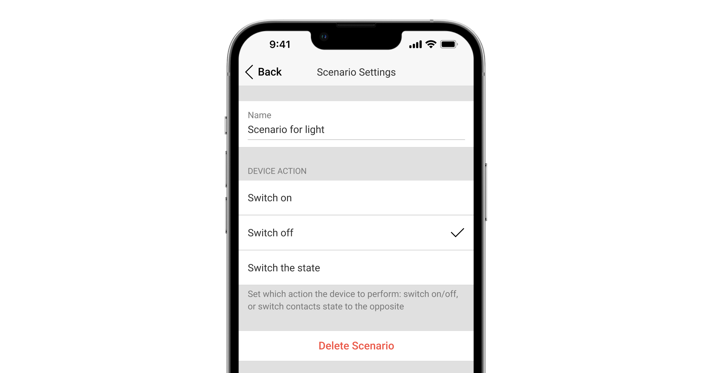
Enter theScenario Nameand specify theDevice Actionto be executed by pressing the Button.
Switch on
Switch off
Switch the state
TheDevice Actionsetting is unavailable when configuring a scenario for theautomation devicesoperating in pulse mode. During the scenario execution, such devices will close/open the contacts for a set time. The operating mode and pulse duration are set in the automation device settings.
ClickNext. The scenario will appear in the list of device scenarios.
Mute Interconnected Fire Detectors Alarm
By pressing the Button, the interconnected fire detectors alarm can be muted (if the corresponding operating mode of the button is selected). The reaction of the system to pressing a button depends on the state of the system:
The Interconnected Fire Detectors Alarm have already propagated- by the first press of the Button, all fire detectors sirens are muted, except for those that registered the alarm. Pressing the button again mutes the remaining detectors.
The interconnected alarms delay time lasts- the siren of the triggered Ajax fire detector is muted by pressing.
Button can be fixed on a surface or carried around.
How to fix Button
To fix Button on a surface (e.g. under a table), use Holder.
To install the button in the holder:
Choose a location to install the holder.
Press the button to test whether the commands can reach the hub. If not, choose another location or use aradio signal range extender.
When connecting Button via radio signal range extender, note that Button does not automatically switch between the radio networks of the radio signal extender and the hub. You can assign Button to another hub or range extender manually in the app.
Fix Holder on the surface using the bundled screws or double-sided adhesive tape.
The button is convenient to carry with you thanks to a special hole on its body. It can be worn on the wrist or around the neck, or hung on a key ring.
Button has an IP55 protection rating. This means that the device body is protected from dust and splashes. Tight buttons are recessed into the body and software protection helps to avoid accidental pressing.
Maintenance
Clean the button body from dust, cobwebs and other contaminants as they appear. Use a soft, dry cloth for cleaning appliances. Never use substances containing alcohol, acetone, gasoline and other active solvents to clean the Button.
The pre-installed battery provides up to 5 years of Button operation in normal use (one press per day). More frequent use may reduce battery life. You can check battery level in the Button states in the Ajax app.
The pre-installed battery is sensitive to low temperatures and if the key fob is cooled significantly, the battery level indicator in the app may show incorrect values until the key fob becomes warmer.
The battery level value is updated each time the button is pressed.
When the battery has run down, the user will receive a notification in the Ajax app, and the LED indicator will smoothly light up red and go out each time the button is pressed.
The warranty for the products manufactured by the Limited Liability Company "Ajax Systems Manufacturing" is valid for 2 years after purchase and does not extend to the bundled battery.
If the device does not function properly, we recommend that you first contact the support service as technical problems can be resolved remotely in most cases.
Buttonis a wireless panic button with protection against accidental press and additional mode to controlautomation devices.
Button is compatible with Ajaxhubsonly. No support forocBridge Plusand uartBridgeintegration modules!
Button is connected to the security system and configured via Ajaxappson iOS, Android, macOS, and Windows. The users are alerted of all alarms and events via push notifications, SMS, and phone calls (if enabled).
Buttonis a wireless panic button that, when pressed, transmits an alarm to users, as well as to the security company's CMS. In Control mode, Button allows you to control Ajax automation devices with a short or long press of a button.
In panic mode, the Button can operate as a panic button and signal about a threat, or notify of the need for auxiliary help, or inform about the intrusion, fire, gas alarm, or leakage. You can select the type of alarm in the button settings. The text of alarm notifications depends on the selected type, as well as the event codes transmitted to the central monitoring station of the security company (CMS).
In the Buttonsettings-Scenariosmenu, you can assign the action of an automation device(Relay,WallSwitchorSocket) to a button press.
The Button is equipped with protection against accidental press and transmits alarms at a distance of up to 1,300 m from the hub. Please be aware that the presence of any obstructions that impede the signal (for example, walls or floors) will reduce this distance.
Button is easy to carry around. You can always keep it on a wrist or a necklace. The device is resistant to dust and splashes.
When connecting Button viaradio signal range extender, please note that Button does not automatically switch between the radio networks of the radio signal extender and the hub. You can manually assign Button to another hub or range extender in the app.
Button has theBattery charge auto-checkoption. When enabled, the system once a day checks the battery state of the button. If the auto-check is disabled, the battery state updates only when the device is pressed.
The feature is available for buttons with firmware version 6.60.0.13 and later. When added to a hub with OS Malevich version 2.17 and later (except Hub (2G) Jeweller and Hub (4G) Jeweller).
Open the Ajaxappand select thespacewhere you want to add the button.
Go to theDevices tab and clickAdd device.
Name the device, scan its QR code (located on the package) or enter it manually, select a room and a group (ifgroup modeis enabled).
ClickAddand the countdown will begin.
Hold the button for 7 seconds. When the Button is added, the LEDs will flash green once.
For detection and pairing, the Button must be located within the hub radio communication zone (on the single protected object).
The connected button will appear in the list of hub devices in the application. Updating the statuses of the device in the list does not depend on the polling time value in the hub settings. Data is updated only by pressing the Button.
The Button only works with one hub. When connected to a new hub, the button Button stops transmitting commands to the old hub. Note that after being added to the new hub, the Button is not automatically removed from the device list of the old hub. This must be done manually through the Ajax application.
States
Button states can be found in the Ajax app:
Ajax app→Devices →Button
Parameter
Value
Data import
Displays the error when transferring data to the new hub:
Failed- the device has not been transferred to the new hub.
Battery level of the device. Two states available:
OK.
Battery discharged.
You can check the battery charge by clicking on the icon (displayed when theBattery Charge Auto-Checkoption is enabled).
The feature is available for buttons with firmware version 6.60.0.13 and later. When added to a hub with OS Malevich version 2.17 and later (except Hub (2G) Jeweller and Hub (4G) Jeweller).
Displays the device's status: active or completely disabled by the user.
Firmware
Button firmware version.
Device ID
Device identifier. Also available on the device's board and its package.
Device No.
Number of the device loop (zone).
Settings
You can adjust the device parameters in the settings section:
Ajax app→ Devices →Button→Settings
Parameter
Value
Name
Name of the device, can be changed.
Room
The choice of the virtual room that the device is assigned to.
Battery charge auto-check
If the toggle is enabled, the system checks the battery state of the device once a day. If the auto-check is disabled, the battery state updates only when the device is pressed.
The feature is available for buttons with firmware version 6.60.0.13 and later. When added to a hub with OS Malevich version 2.17 and later (except Hub (2G) Jeweller and Hub (4G) Jeweller).
Notify if the device was unreachable for 3 days
When the toggle is enabled, the user receives a corresponding notification if the button has not communicated with the hub for three days. The setting is available when theBattery charge auto-checktoggle is enabled.
Operating mode
Displays the operating mode of the button. Three modes are available:
Panic- sends an alarm when pressed.
Control- controls automation devices by short or long (3 sec) pressing.
Mute Fire Alarm- when pressed, mutes the alarm of Ajax fire detectors. The option is available ifInterconnected Fire Alarmfeature is enabled.
The text of SMS and notifications in the app depends on the selected type of alarm.
LED brightness
This displays the current brightness of the indicator lights:
Disabled (LED indication is disabled).
Low.
Max.
Accidental press protection
(displayed only forPanicand MuteFire Alarmoperating modes)
Displays the selected type of protection against accidental activation:
Off- protection disabled.
Long press- in order to send an alarm, you need to press and hold the button for more than 1.5 seconds.
Double press- in order to send an alarm, you need to double-press the button with a pause of no more than 0.5 seconds between the presses.
Alert with a siren if button is pressed
If the toggle is enabled, pressing a panic button activates Ajaxsirensconnected to the system. Ajax Button activates all sirens, regardless of the groups they are in.
Scenarios
Opens the menu for creating and configuring scenarios.
Battery state check
Opens the menu for the battery charge checking.
The feature is available for buttons with firmware version 6.60.0.13 and later. When added to a hub with OS Malevich version 2.17 and later (except Hub (2G) Jeweller and Hub (4G) Jeweller).
User guide
Opens Button User manual.
Permanent deactivation
Allows a user to deactivate the device without deleting it from the system.
Once deactivated, the device will no longer execute system commands and participate in automation scenarios. Additionally, the panic button of a deactivated device will be disabled.
Disconnects Button from the hub and deletes its settings.
Operating indication
Button status is indicated with red or green LED indicators.
Category
Indication
Event
Adding or removing from the hub. Changing the battery
Green LEDs flash 3 times.
The button is not added to any hub.
The indication is available for buttons with firmware version 6.60.X.X and later.
Green LEDs flash 6 times.
The button is removed from the hub, or the battery is changed.
The indication is available for buttons with firmware version 6.60.X.X and later. For newer firmware versions, this indication means that the button is not added to any hub.
Lights up green for a few seconds.
Adding the button to the hub.
Command delivery indication
Lights up green briefly.
Command is delivered to the hub.
Lights up red briefly.
Command is not delivered to the hub.
Long press indication in Control mode
Flashes green briefly.
Button recognised the pressing as a long press and sent the corresponding command to the hub.
Feedback Indication
(follows theCommand Delivery Indication)
Lights up green for about half a second after the command delivery indication.
The hub has received and performed the command.
Briefly lights up red after the command delivery indication.
The hub did not perform the command.
Battery status
(followsFeedback Indication)
After the main indication it lights up red and goes out smoothly.
Button battery needs to be replaced. At the same time, button commands are delivered to the hub.
In the panic button mode, Button can call security or help, as well as alert of an emergency by activating sirens and sending other users a notification in the app. In the Button settings, you can select one type of alarm out of eight:
Intrusion
Fire
Auxiliary alarm
Panic button
Gas alarm
Malfunction
Leakage
Custom (not sent to the security company monitoring station)
The type of alarm determines the event code sent to the security company monitoring station (CMS) and the notification text received by the user. This ensures the accurate response to the threat.
Note that inPanic Mode, pressing the Button will raise an alarm regardless of the system security mode.
If Button is pressed, an alarm can alsorun a scenarioin the Ajax system.
Button can be installed on a flat surface or carried around. To install on a flat surface (for example, under the table), secure the Button with double-sided adhesive tape. To carry the Button on the strap: attach the strap to the Button using the mounting hole in the main body of the Button.
Control Mode
Button can be used to control the automation devices. InControl mode, the Button has two pressing options: short and long (the button is pressed for more than 3 seconds). These pressings can trigger the execution of an action by one or more automation devices: Relay, WallSwitch, or Socket.
To bind an automation device action to a long or short press of a Button:
SelectButtonin the list of devices and go to settings by clicking the gear icon .
Select theControlmode in theOperation mode section. Click on the actualButtondevice to save the changes
Go to theScenariosmenu. ClickCreate Scenarioif you are creating a scenario for the first time, orAdd Scenarioif scenarios have already been created in the security system.
Select a pressing option to run the scenario:Short pressorLong press.
Select the automation device to execute the action.
Enter theScenario Nameand specify theDevice Actionto be executed by pressing the Button.
Switch on
Switch off
Switch the state
TheDevice Actionsetting is unavailable when configuring a scenario for theautomation devicesoperating in pulse mode. During the scenario execution, such devices will close/open the contacts for a set time. The operating mode and pulse duration are set in the automation device settings.
ClickNext. The scenario will appear in the list of device scenarios.
Mute Interconnected Fire Detectors Alarm
By pressing the Button, the interconnected fire detectors alarm can be muted (if the corresponding operating mode of the button is selected). The reaction of the system to pressing a button depends on the state of the system:
The Interconnected Fire Detectors Alarm have already propagated- by the first press of the Button, all fire detectors sirens are muted, except for those that registered the alarm. Pressing the button again mutes the remaining detectors.
The interconnected alarms delay time lasts- the siren of the triggered Ajax fire detector is muted by pressing.
Button can be fixed on a surface or carried around.
How to fix Button
To fix Button on a surface (e.g. under a table), use Holder.
To install the button in the holder:
Choose a location to install the holder.
Press the button to test whether the commands can reach the hub. If not, choose another location or use aradio signal range extender.
When connecting Button via radio signal range extender, note that Button does not automatically switch between the radio networks of the radio signal extender and the hub. You can assign Button to another hub or range extender manually in the app.
Fix Holder on the surface using the bundled screws or double-sided adhesive tape.
The button is convenient to carry with you thanks to a special hole on its body. It can be worn on the wrist or around the neck, or hung on a key ring.
Button has an IP55 protection rating. This means that the device body is protected from dust and splashes. Tight buttons are recessed into the body and software protection helps to avoid accidental pressing.
Maintenance
Clean the button body from dust, cobwebs and other contaminants as they appear. Use a soft, dry cloth for cleaning appliances. Never use substances containing alcohol, acetone, gasoline and other active solvents to clean the Button.
The pre-installed battery provides up to 5 years of Button operation in normal use (one press per day). More frequent use may reduce battery life. You can check battery level in the Button states in the Ajax app.
The pre-installed battery is sensitive to low temperatures and if the key fob is cooled significantly, the battery level indicator in the app may show incorrect values until the key fob becomes warmer.
The battery level value is updated each time the button is pressed.
When the battery has run down, the user will receive a notification in the Ajax app, and the LED indicator will smoothly light up red and go out each time the button is pressed.
The warranty for the products manufactured by the Limited Liability Company "Ajax Systems Manufacturing" is valid for 2 years after purchase and does not extend to the bundled battery.
If the device does not function properly, we recommend that you first contact the support service as technical problems can be resolved remotely in most cases.
{"id":46870133211471,"title":"Default Title","option1":"Default Title","option2":null,"option3":null,"sku":"367304862","requires_shipping":true,"taxable":true,"featured_image":null,"available":true,"name":"AJAX Wireless security system remote control SpaceControl in white","public_title":null,"options":["Default Title"],"price":2940,"weight":0,"compare_at_price":3749,"inventory_management":"shopify","barcode":null,"requires_selling_plan":false,"selling_plan_allocations":[],"quantity_rule":{"min":1,"max":null,"increment":1}}
AJAX Wireless security system remote control SpaceControl in white
SKU: 367304862
€29,40€37,49
Unit price
Wireless remote control SpaceControlwith an alarm button. WithSpaceControl help or turn on and off security, turn on night mode, send an alarm.
Control of the entire security system is available in the Ajax app on a smartphone, but if you have a discharged phone, you can use the SpaceControl console.
Ready to work immediately: the battery is inside the remote control. Simple addition of the device to your security system - by scanning the QR code in the Ajax app.
Battery life 5 years .
Operating temperature: from -25°С to +50°С
Size: 65 × 37 × 10 mm
Weight: 13 years
There is no warranty for the batteries.
The installation instructions are available in the Ajax app, which will open by scanning the QR code of the detector at the time of installation. Easy installation and connection to the Ajax central Hub.
Available for pickup at
Out of stock at
Added to compare
Reached count_product-product limit
Added to compare
Reached count_product-product limit
{"id":41592061165751,"title":"Default Title","option1":"Default Title","option2":null,"option3":null,"sku":"367304861","requires_shipping":true,"taxable":true,"featured_image":null,"available":true,"name":"AJAX Wireless security system remote control SpaceControl Black","public_title":null,"options":["Default Title"],"price":2940,"weight":0,"compare_at_price":3749,"inventory_management":"shopify","barcode":null,"requires_selling_plan":false,"selling_plan_allocations":[],"quantity_rule":{"min":1,"max":null,"increment":1}}
AJAX Wireless security system remote control SpaceControl Black
SKU: 367304861
(1)
€29,40€37,49
Unit price
Wireless remote control SpaceControlwith an alarm button. WithSpaceControl help or turn on and off security, turn on night mode, send an alarm.
Control of the entire security system is available in the Ajax app on a smartphone, but if you have a discharged phone, you can use the SpaceControl console.
Ready to work immediately: the battery is inside the remote control. Simple addition of the device to your security system - by scanning the QR code in the Ajax app.
Battery life 5 years .
Operating temperature: from -25°С to +50°С
Size: 65 × 37 × 10 mm
Weight: 13 years
There is no warranty for the batteries.
The installation instructions are available in the Ajax app, which will open by scanning the QR code of the detector at the time of installation. Easy installation and connection to the Ajax central Hub.
Available for pickup at
Out of stock at
Added to compare
Reached count_product-product limit
Added to compare
Reached count_product-product limit
{"id":55852902744399,"title":"Default Title","option1":"Default Title","option2":null,"option3":null,"sku":"367304808","requires_shipping":true,"taxable":true,"featured_image":null,"available":true,"name":"Ajax 6V Power Supply for Hub 2\/Hub 2 Plus\/ReX 2","public_title":null,"options":["Default Title"],"price":2351,"weight":0,"compare_at_price":2997,"inventory_management":"shopify","barcode":"810031991037","requires_selling_plan":false,"selling_plan_allocations":[],"quantity_rule":{"min":1,"max":null,"increment":1}}
6V PSU (type A)is an alternative power supply unit to connect an Ajax hub or range extender to 6 V⎓ sources. This is an electronic board, replacing the standard 110/230 V⎓ power supply unit in the body of the device.
6V PSU (type A) should be installed by a qualified electrician only.
Before installing the power supply, ensure the device is disconnected from the mains.
When installing the 6V PSU for Hub 2/Hub 2 Plus/ReX 2, follow the general electrical safety rules, as well as the requirements of electrical safety regulatory acts. Never disassemble the device while it is under voltage!
Installation process:
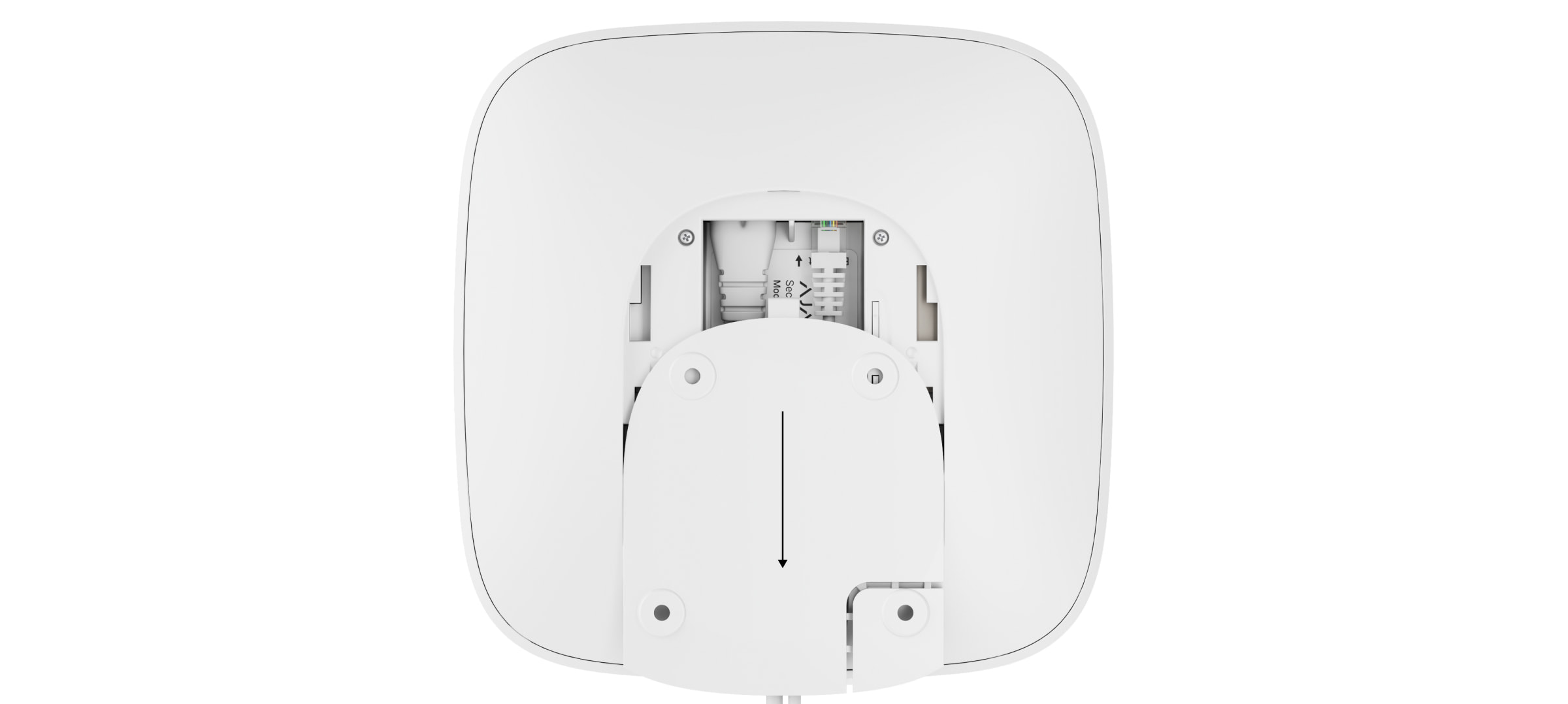
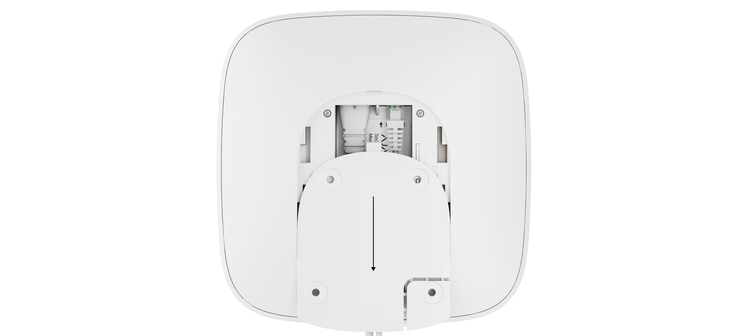
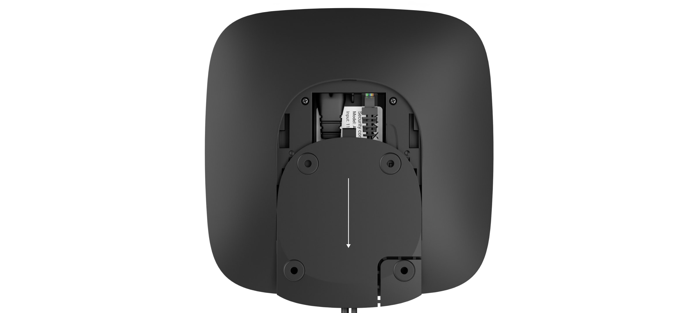
Remove the screws and take off the device from the SmartBracket mounting panel, shifting it down with force. If the hub or range extender is installed on a surface, move it upwards.
Switch off the device holding the power button for 2 seconds.
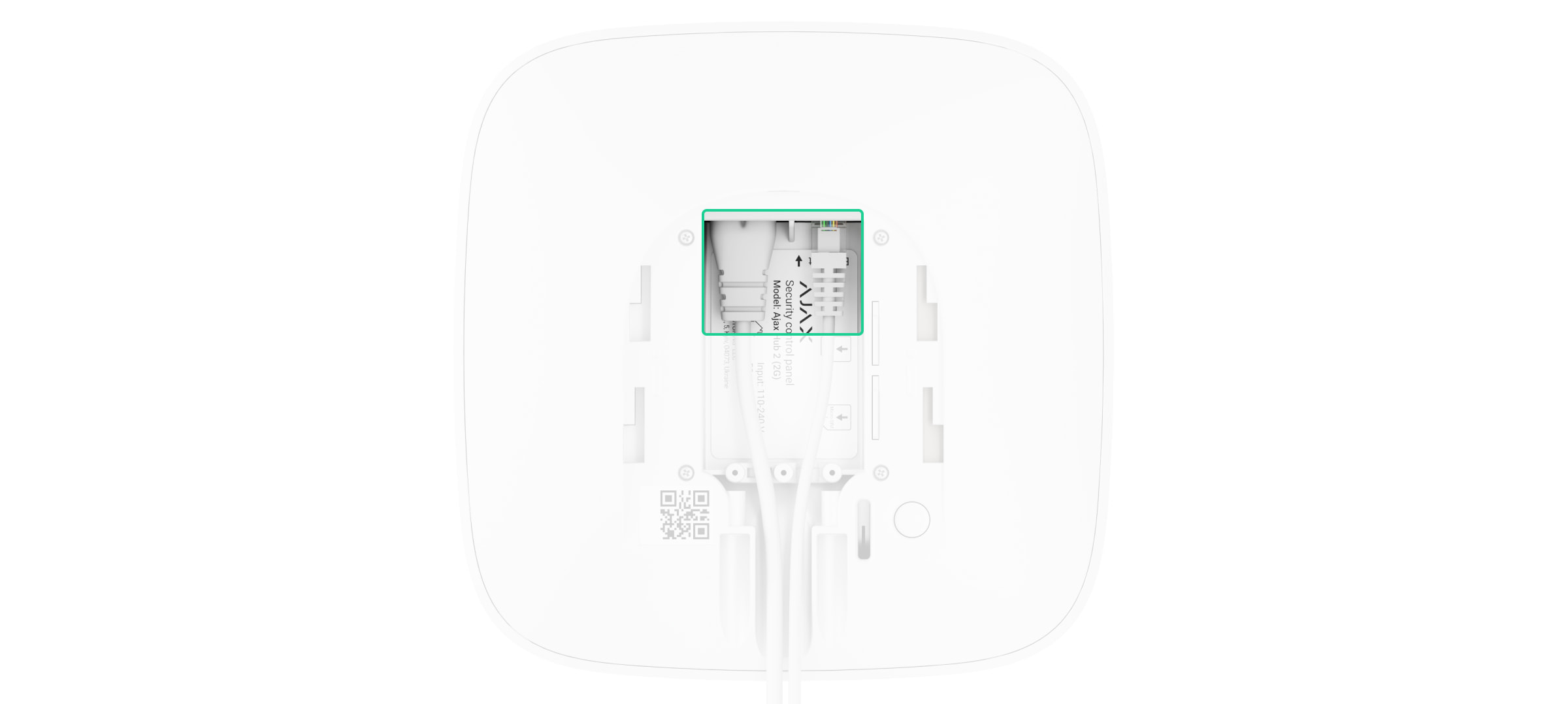
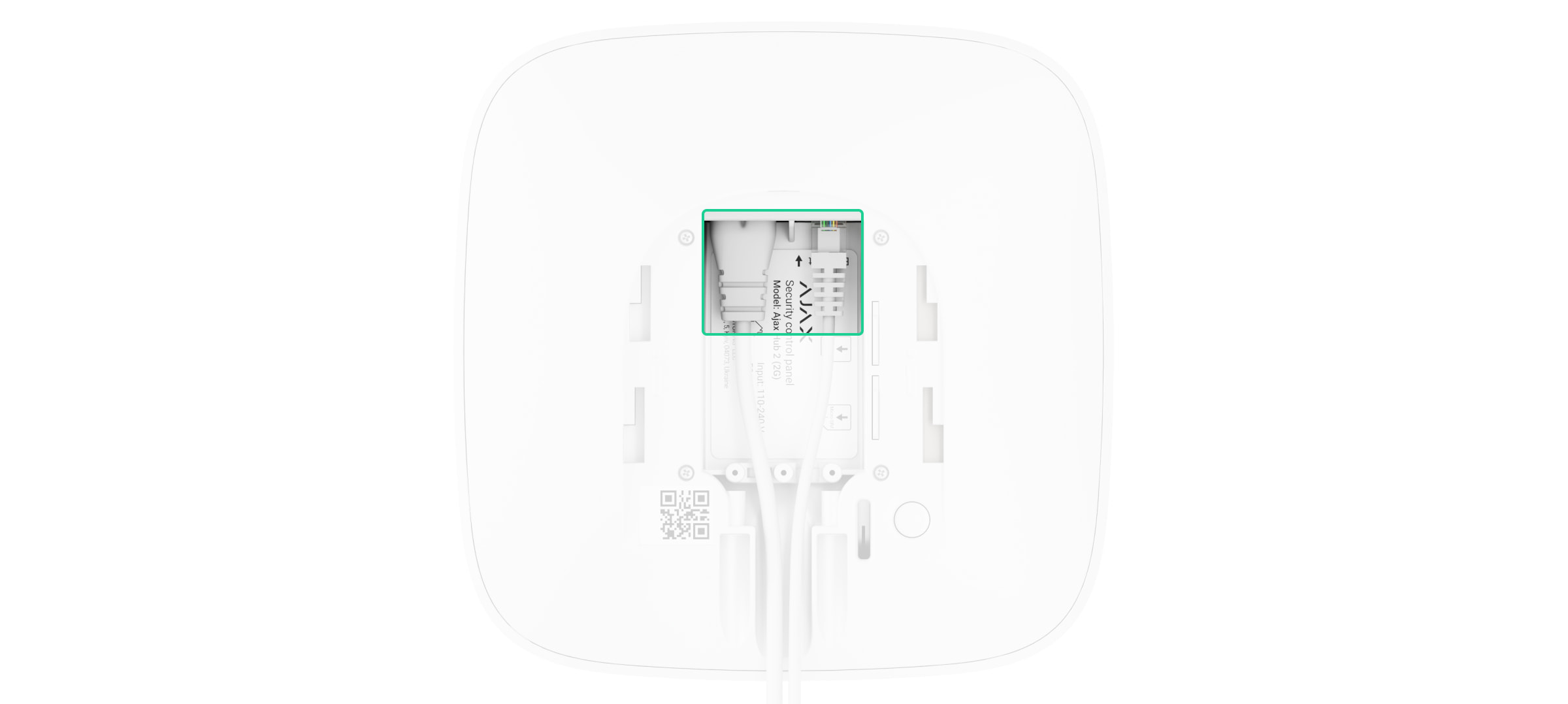
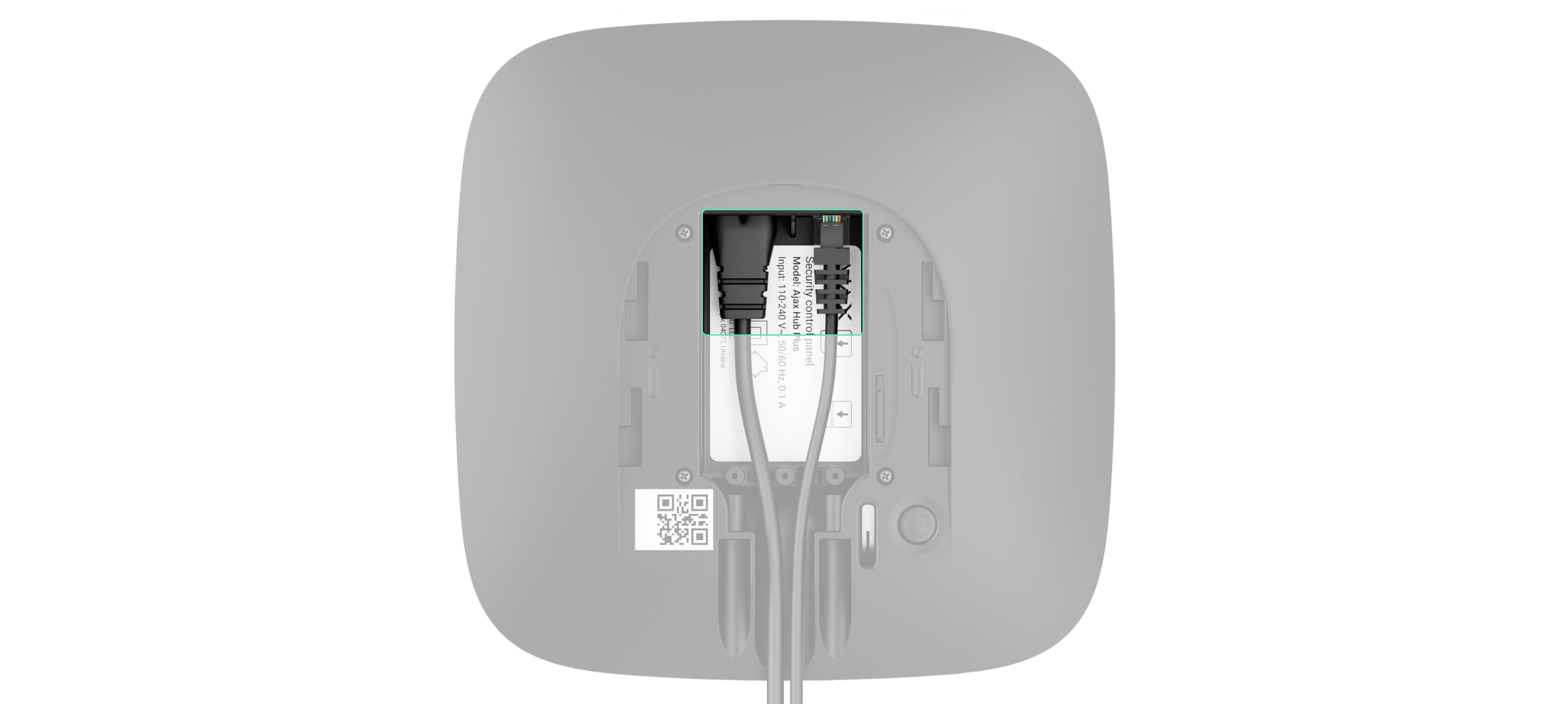
Disconnect power and Ethernet cables.
Wait 5 minutesafter switching off for the capacitors to discharge.
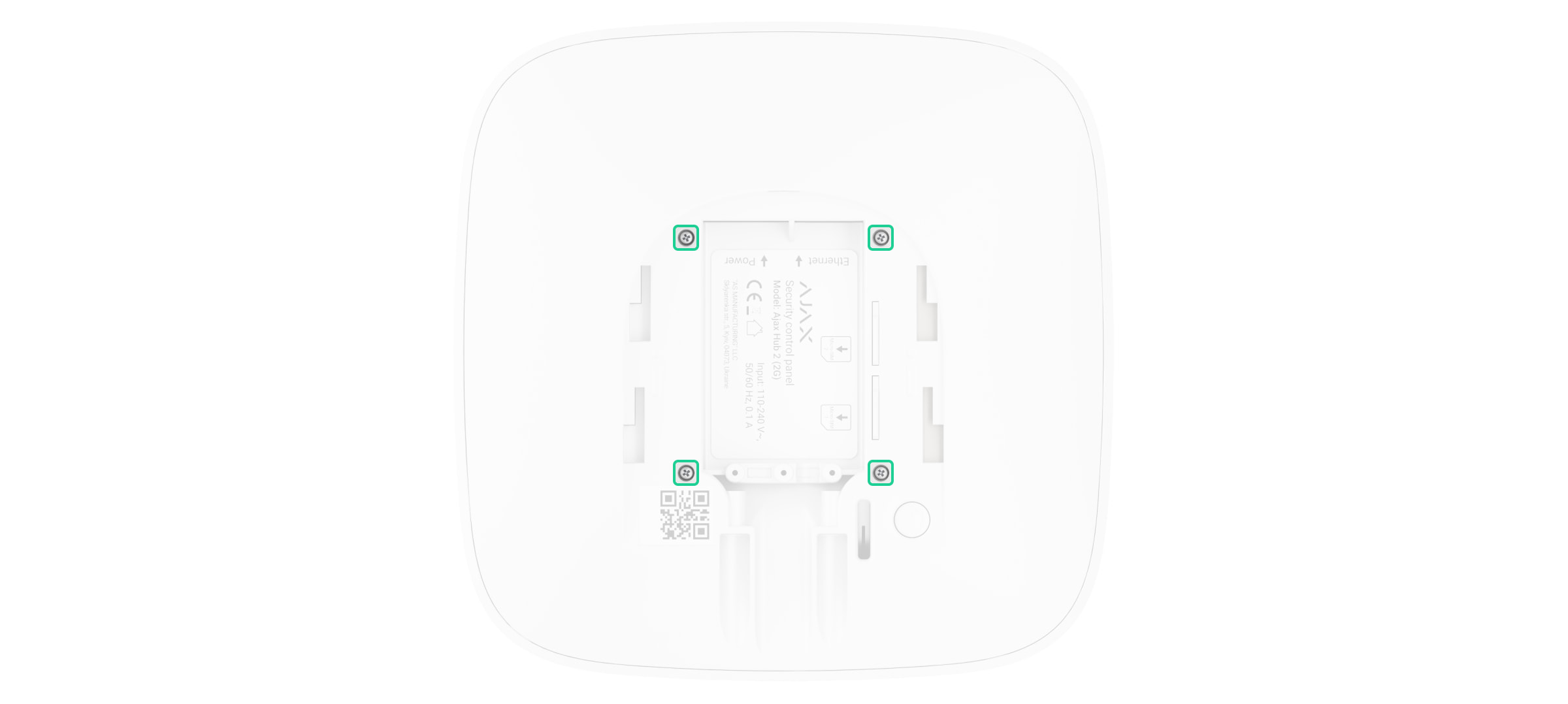
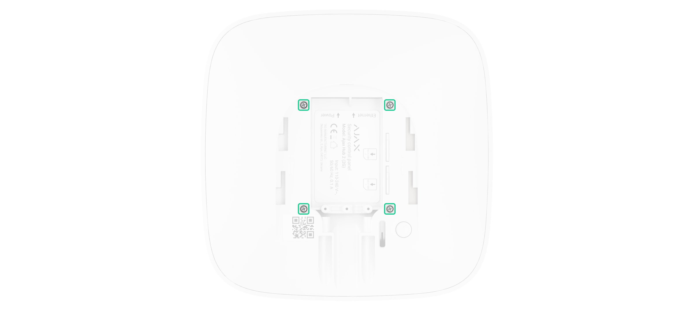
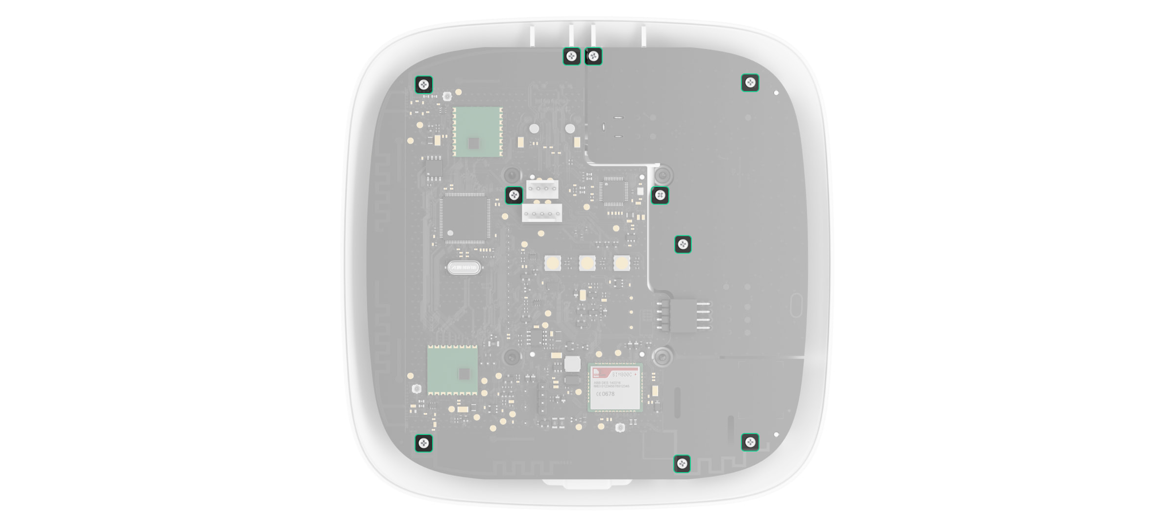
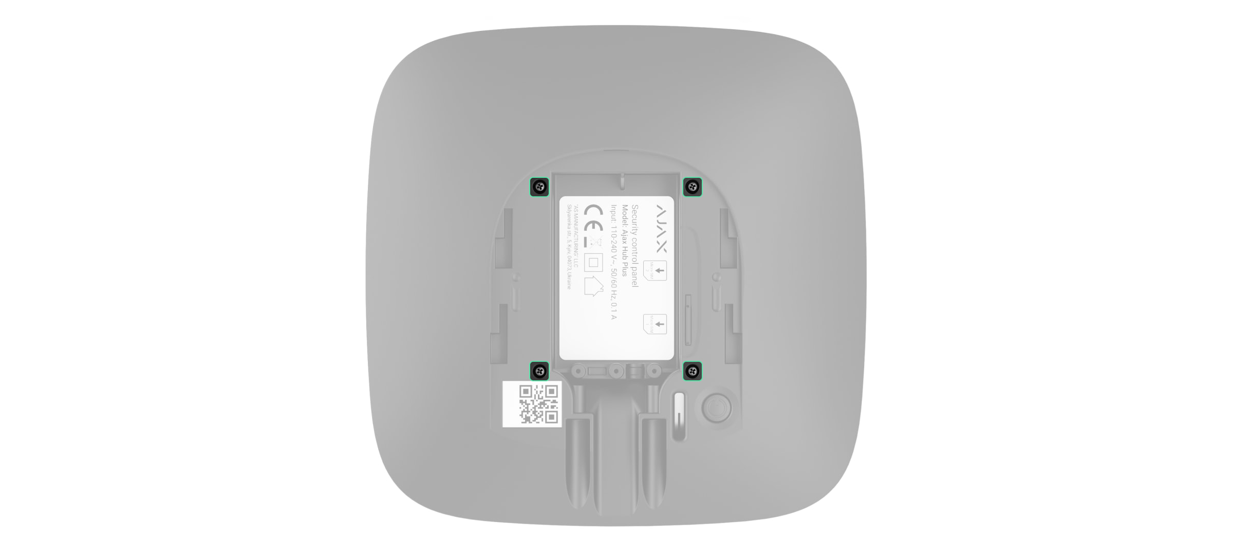
Remove four screws of the back lid and take it off.
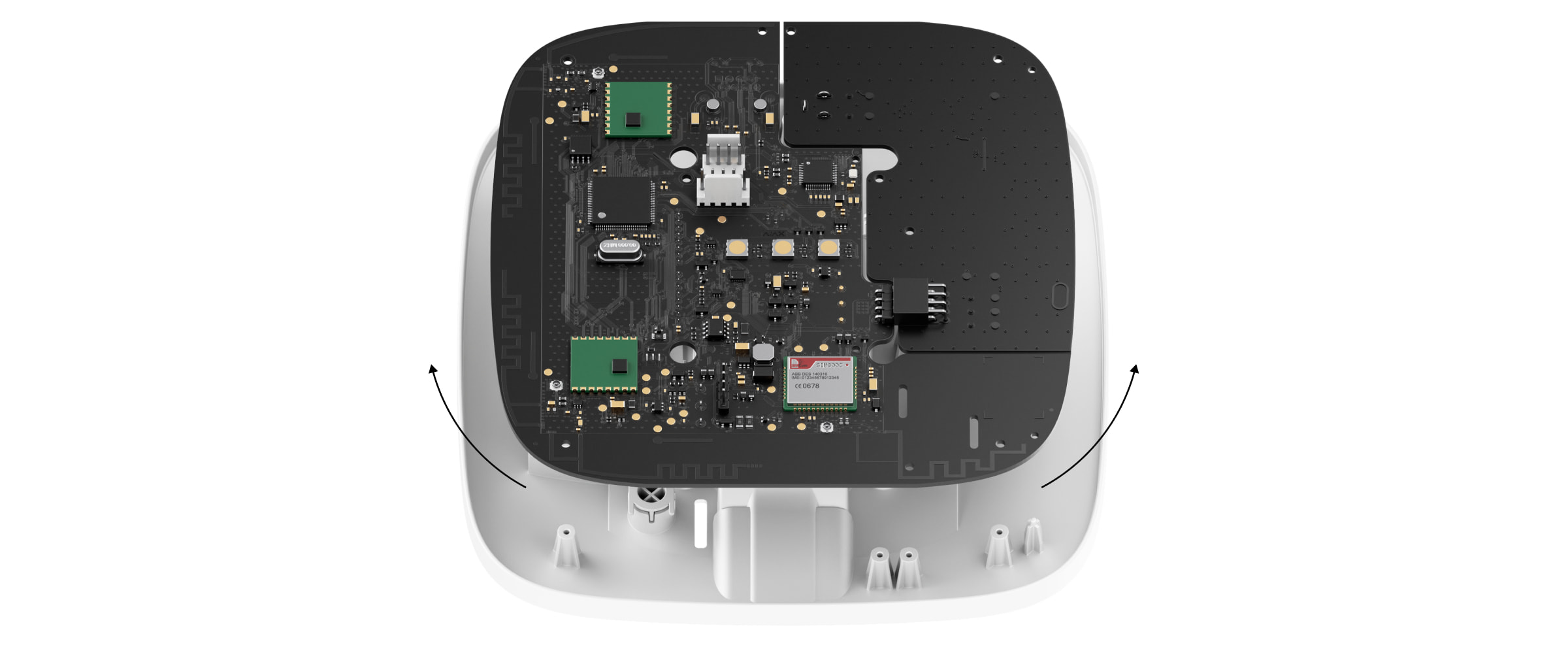
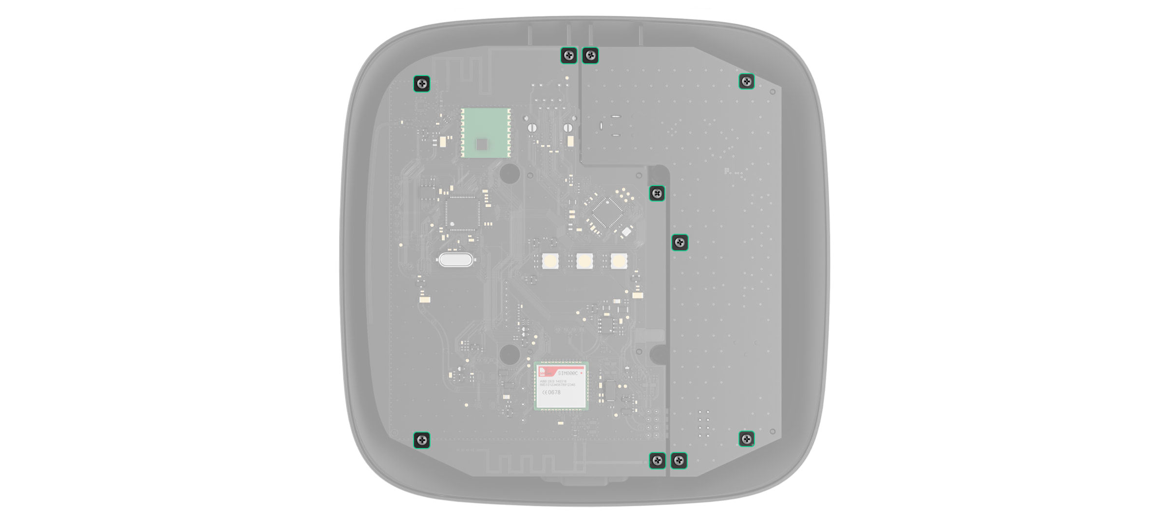
Remove the screws attaching the boards to the device body.
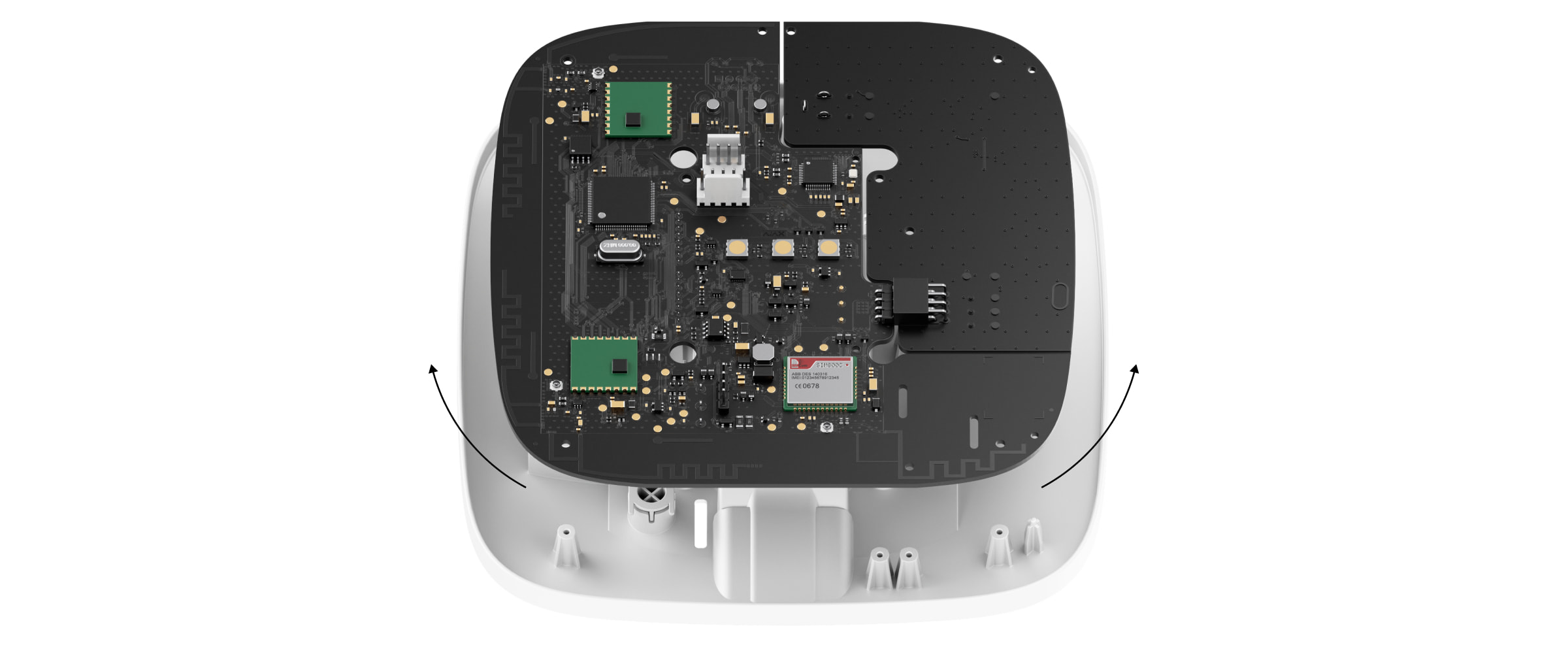
Carefully remove both boards, keeping them in the same plane and not disconnecting them. There is a connector between boards: do not break it.
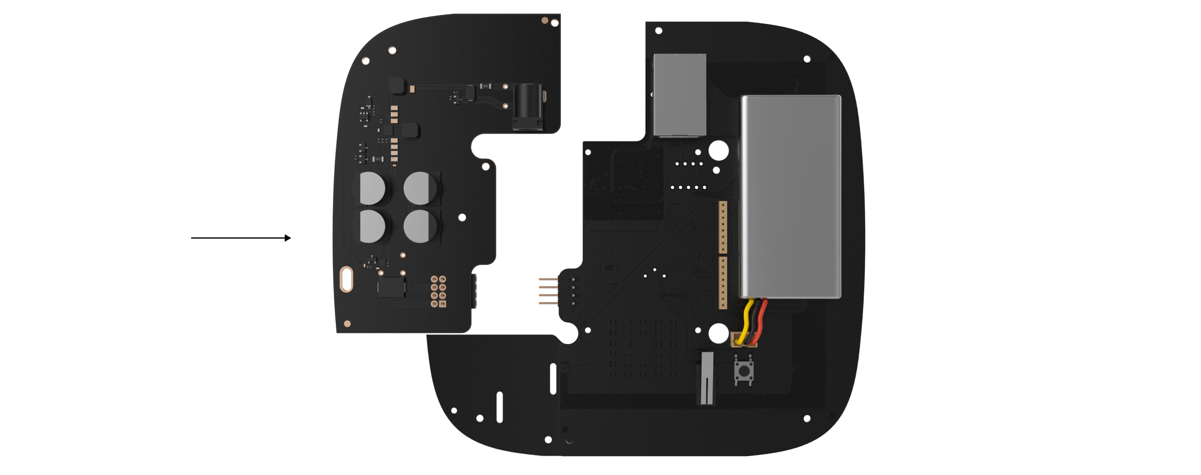
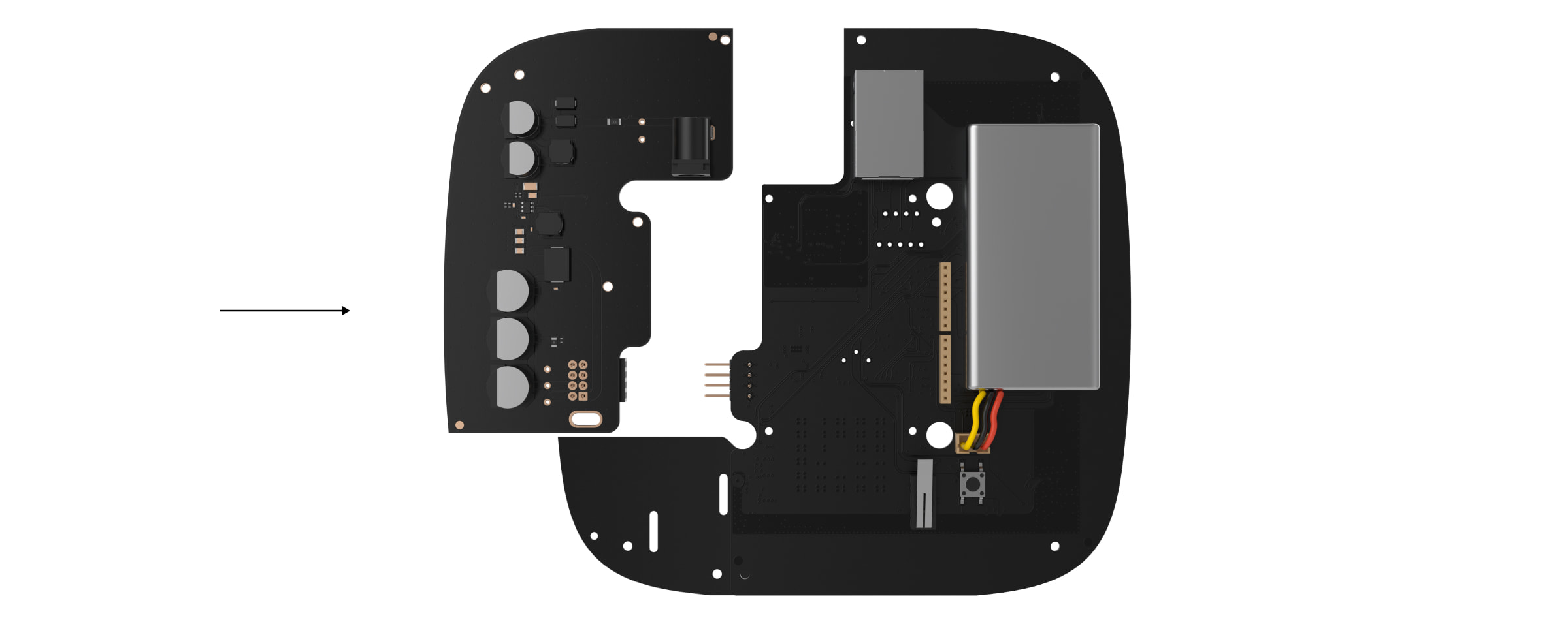
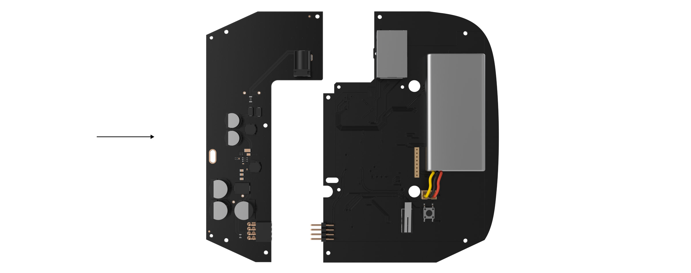
Disconnect the power supply unit (smaller board) from the mainboard.
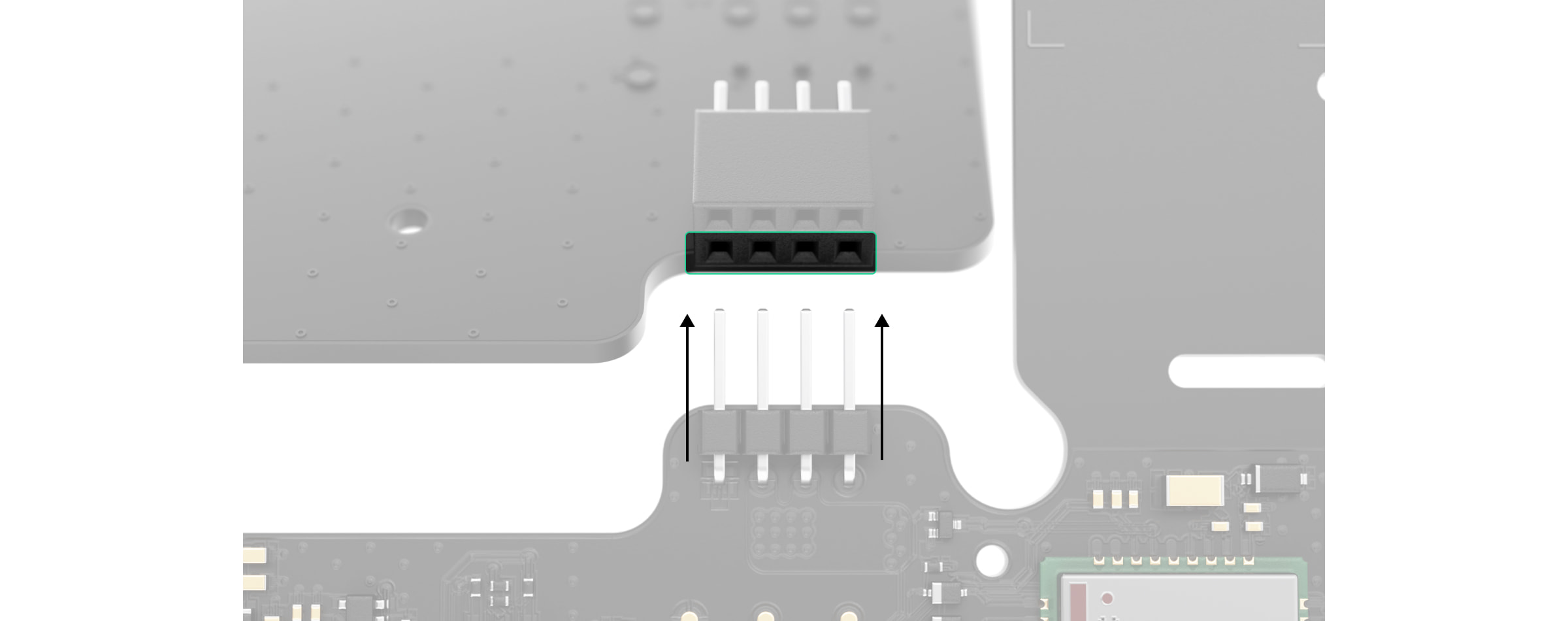
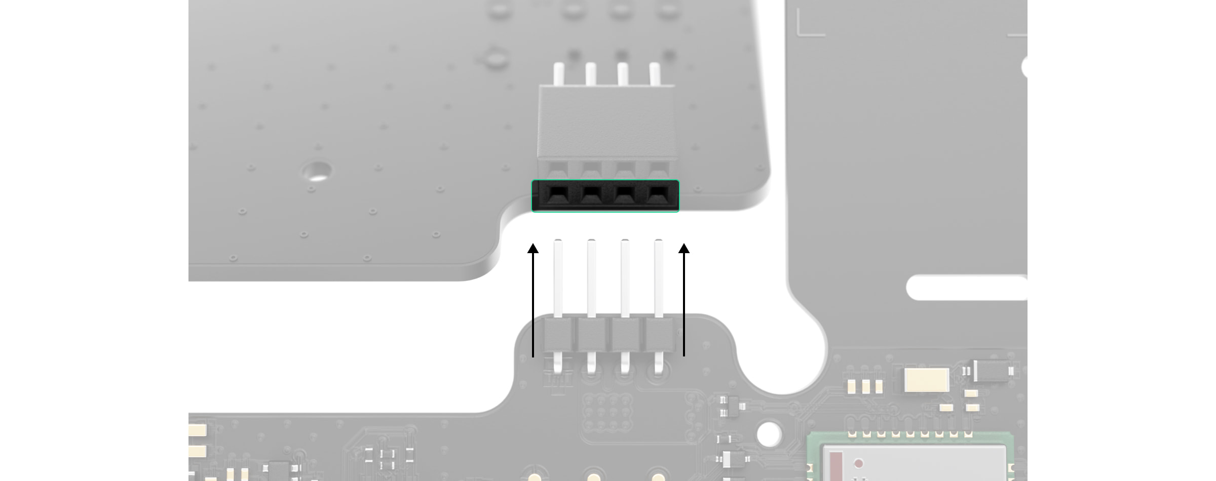
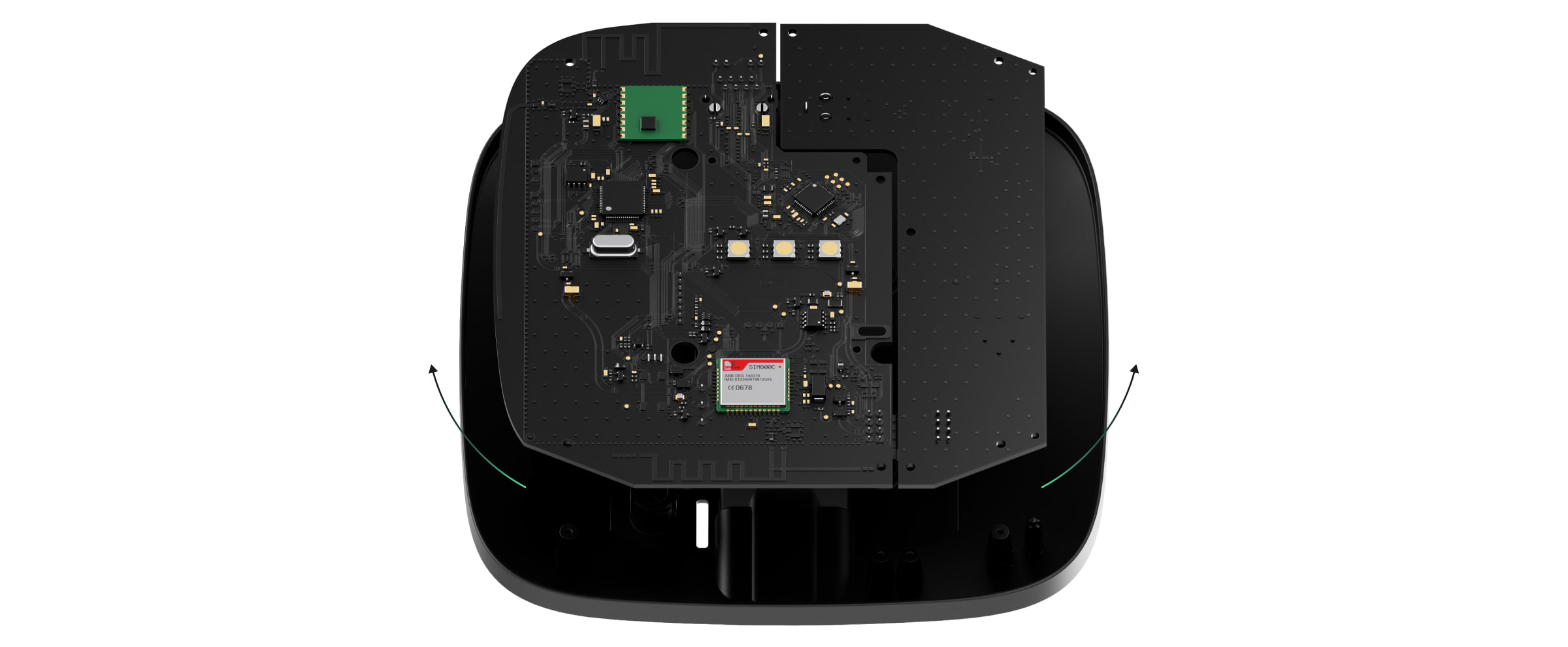
Connect 6V PSU (type A) to the mainboard using the eight-pin connector between them. Do not warp or bend the antennas while replacing the board: this can cause the device to malfunction.
Please note: the board contacts should be plugged in the bottom row of the connector (closest to the board). When connected correctly, the boards are on the same level.
Reassemble the boards and the device body then tighten the screws.
Check that the battery and its cables are not clamped. When installed properly, the boards stand firmly on all guides and do not stagger. Holding the boards together with the back lid, turn the device over. The SIM card slots, power, and Ethernet sockets should match accurately and fit the corresponding sockets, and the power button should not be stuck.
Check the information about input voltage on the device body to avoid incorrect power connections in the future. Use the special bundled sticker with the instruction.
Connect the power (and Ethernet cable) to the appropriate sockets.
Switch on the 6 V⎓ power source.
Do not connect the power cable with a voltage that exceeds the acceptable input voltage.
Switch on the device by holding the power button for 2 seconds.
Install the hub or range extender onthe SmartBracket mounting panel.Fix the device.
Switch on the device, wait until loading, and check the external power status in the Ajax app. If there is no power, and you are using a terminal adapter, check the polarity of thepower cable. If there is no power even after reconnecting, pleasecontact the Support Service.
We recommend using zinc-air alkaline batteries for long-term autonomous operation. Before connecting such a battery, make sure that all the stickers have been removed, and valves capping the air access are open. If possible, leave the battery with access to air for up to 2 hours. This will start a chemical reaction inside and ensure proper functioning.
12V PSU for Hub 2/ReX 2is a power supply unit, connecting theHub 2control panels to 12 volt DC sources. This is an electronic board, replacing the standard 110/230 V power supply unit in the body of the device.
12V PSU for Hub 2/ReX 2 should be installed by a qualified electrician only.
Before installing the power supply, make sure that the device is disconnected from the mains.
When installing the 12V PSU for Hub 2/ReX 2, follow the general electrical safety rules, as well as the requirements of electrical safety regulatory acts. Never disassemble the device while it is under voltage!
Installation process:
Remove the screws and take off the device from the SmartBracket mounting panel, shifting it down with force.
Switch off the device holding the power button for 2 seconds.
Disconnect power and Ethernet cables.
Wait 5 minutes for the capacitors to discharge.
Remove four screws of the back lid and take it off.
Remove the screws attaching the boards to the device body.
Carefully remove both boards, keeping them in the same plane and not disconnecting them. There is a connector between boards: do not break it.
Disconnect the power supply unit (smaller board) from the mainboard.
Connect 12V PSU for Hub 2/ReX 2 to the mainboard using the eight-pin connector between them. Do not warp or bend the antennas while replacing the board: this can cause the device to malfunction.
Please note: the board contacts should be plugged in the bottom row of the connector (closest to the board). When connected correctly, the boards are on the same level.
Reassemble the boards and the device body than tighten the screws.
Check that the battery and its cables are not clamped. When installed properly, the boards stand firmly on all guides and do not stagger. Holding the boards together with the back lid, turn the device over. The SIM card slot, power, and Ethernet sockets should match accurately and fit the corresponding sockets, and the power button should not be stuck. Change the information about input voltage on the device body to avoid incorrect power connections in the future. Use the special bundled sticker with the instruction.
Connect the power (and Ethernet cable) to the appropriate sockets.
Switch on the 12 V power source.
Do not connect the power cable with a voltage that exceeds the acceptable input voltage.
Switch on the device by holding the power button for 2 seconds.
Close and fix the SmartBracket mounting panel.
Switch on the device, wait until loading, and check the external power status in the Ajax app. If there is no power, and you are using a terminal adapter, check the polarity of the connected wires. If there is no power even after reconnecting, please contact the Support Service.
Maintenance
The device does not require technical maintenance.
{"id":55852831408463,"title":"Default Title","option1":"Default Title","option2":null,"option3":null,"sku":"367304807","requires_shipping":true,"taxable":true,"featured_image":null,"available":true,"name":"Ajax 12V Power Supply for Hub\/Hub Plus\/ReX","public_title":null,"options":["Default Title"],"price":2351,"weight":0,"compare_at_price":2997,"inventory_management":"shopify","barcode":"810031990498","requires_selling_plan":false,"selling_plan_allocations":[],"quantity_rule":{"min":1,"max":null,"increment":1}}
12V PSU for Hub/Hub Plus/ReXis a power supply unit, connecting the Hub/Hub Plus control panels as well as the ReX radio signal extender to 12 volt DC sources. This is an electronic board, replacing the standard 110/230 V power supply unit in the body of the device.
12V PSU for Hub/Hub Plus/ReX should be installed by a qualified electrician only.
Before installing the power supply, make sure that the device is disconnected from the mains.
When installing the 12V PSU for Hub/Hub Plus/ReX, follow the general electrical safety rules, as well as the requirements of electrical safety regulatory acts. Never disassemble the device while it is under voltage!
Installation process:
Remove the screws and take off the hub or range extender from the SmartBracket mounting panel, shifting the device up.
Switch off the hub or range extender holding the power button for 2 seconds.
Disconnect power and Ethernet cables.
Wait 5 minutes for the capacitors to discharge.
Remove four screws of the back lid and take it off.
Remove the screws attaching the boards to the device body.
Carefully remove both boards, keeping them in the same plane and not disconnecting them. There is a connector between boards: do not break it.
Disconnect the power supply unit (smaller board) from the mainboard.
Connect 12V PSU Hub/Hub Plus/ReX to the mainboard using the eight-pin connector between them. Do not warp or bend the antennas while replacing the board: this can cause the device to malfunction.
Reassemble the boards and the device body than tighten the screws.
Check that the battery and its cables are not clamped. When installed properly, the boards stand firmly on all guides and do not stagger. Holding the boards together with the back lid, turn the device over. The SIM card slot, power, and Ethernet sockets should match accurately and fit the corresponding sockets, and the power button should not be stuck.
Change the information about input voltage on the device body to avoid incorrect power connections in the future. Use the special bundled sticker with the instruction included in the set.
Connect the power (and Ethernet cable) to the appropriate sockets.
Switch on the power source to the hub or range extender.
Do not connect the power cable with a voltage that exceeds the acceptable input voltage 12V PSU for Hub/Hub Plus/ReX.
Switch on the device by holding the power button for 2 seconds.
Close and fix the SmartBracket mounting panel.
Switch on the device, wait until loading, and check the external power status in the Ajax app. If there is no power, and you are using a terminal adapter, check the polarity of the connected wires. If there is no power even after reconnecting, pleasecontact the Ajax Support Service.
Maintenance
The device does not require technical maintenance.
{"id":55844753211727,"title":"Default Title","option1":"Default Title","option2":null,"option3":null,"sku":"External Antenna black","requires_shipping":true,"taxable":true,"featured_image":null,"available":true,"name":"AJAX Antenna for LTE or radio communication, Standard SMA connector, Wired communication up to 3 m, Installation using double-sided tape","public_title":null,"options":["Default Title"],"price":2181,"weight":0,"compare_at_price":2781,"inventory_management":"shopify","barcode":null,"requires_selling_plan":false,"selling_plan_allocations":[],"quantity_rule":{"min":1,"max":null,"increment":1}}
A compatible Ajax hub is required for the antenna to work.
The device is compatible with:
Hub BP Jeweller
ExternalAntenna sold separately.
Operating principle
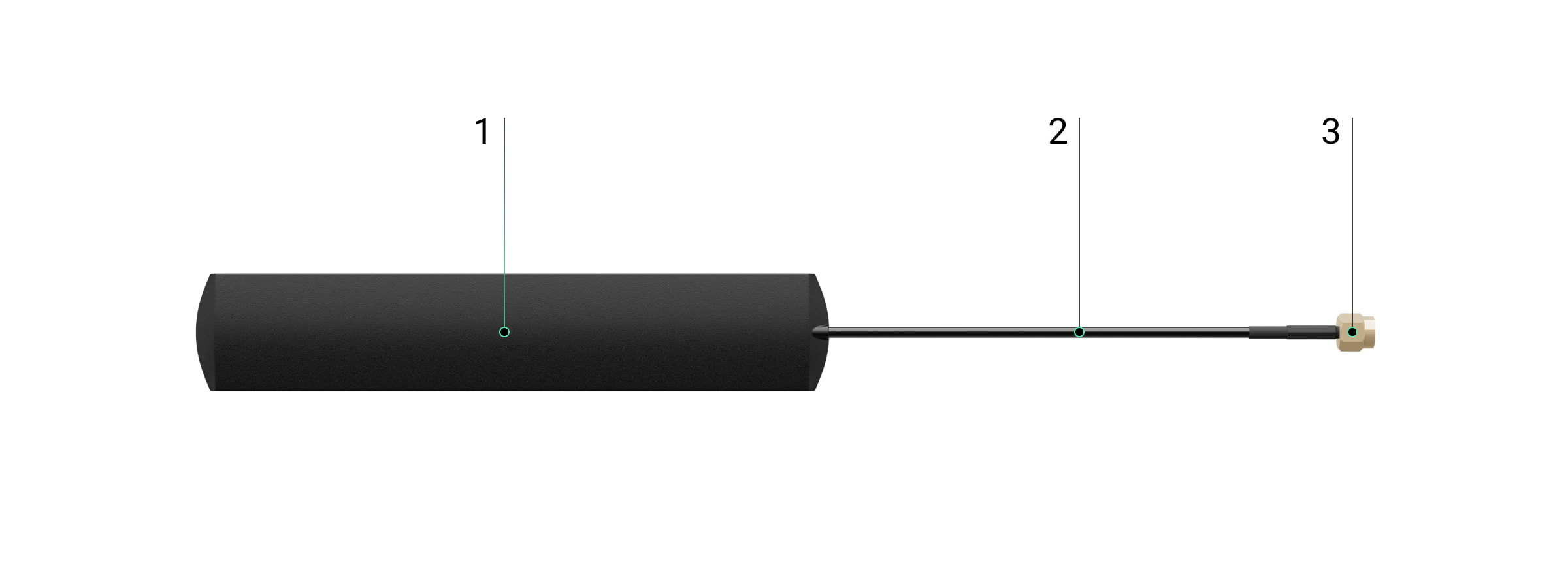
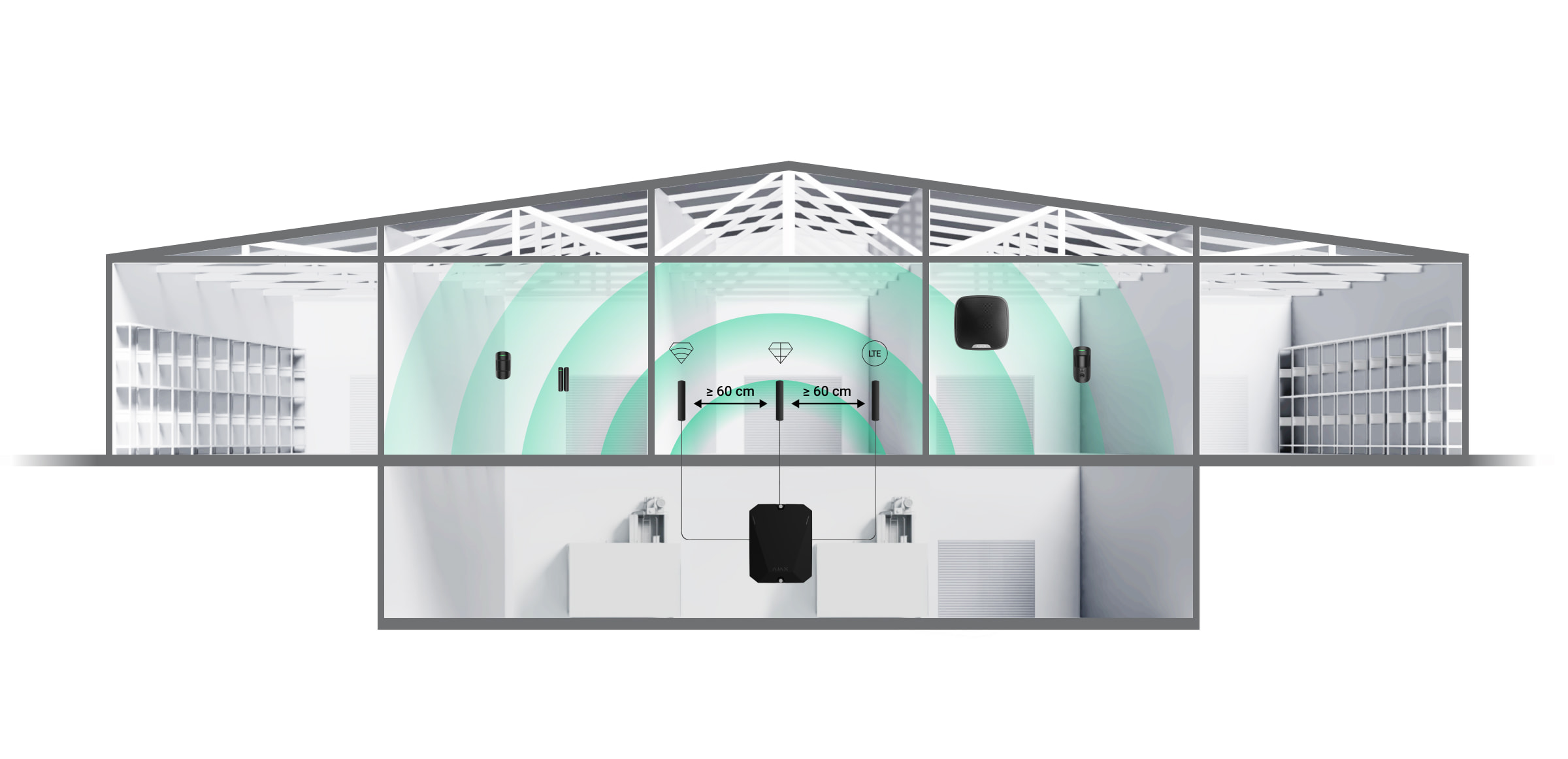
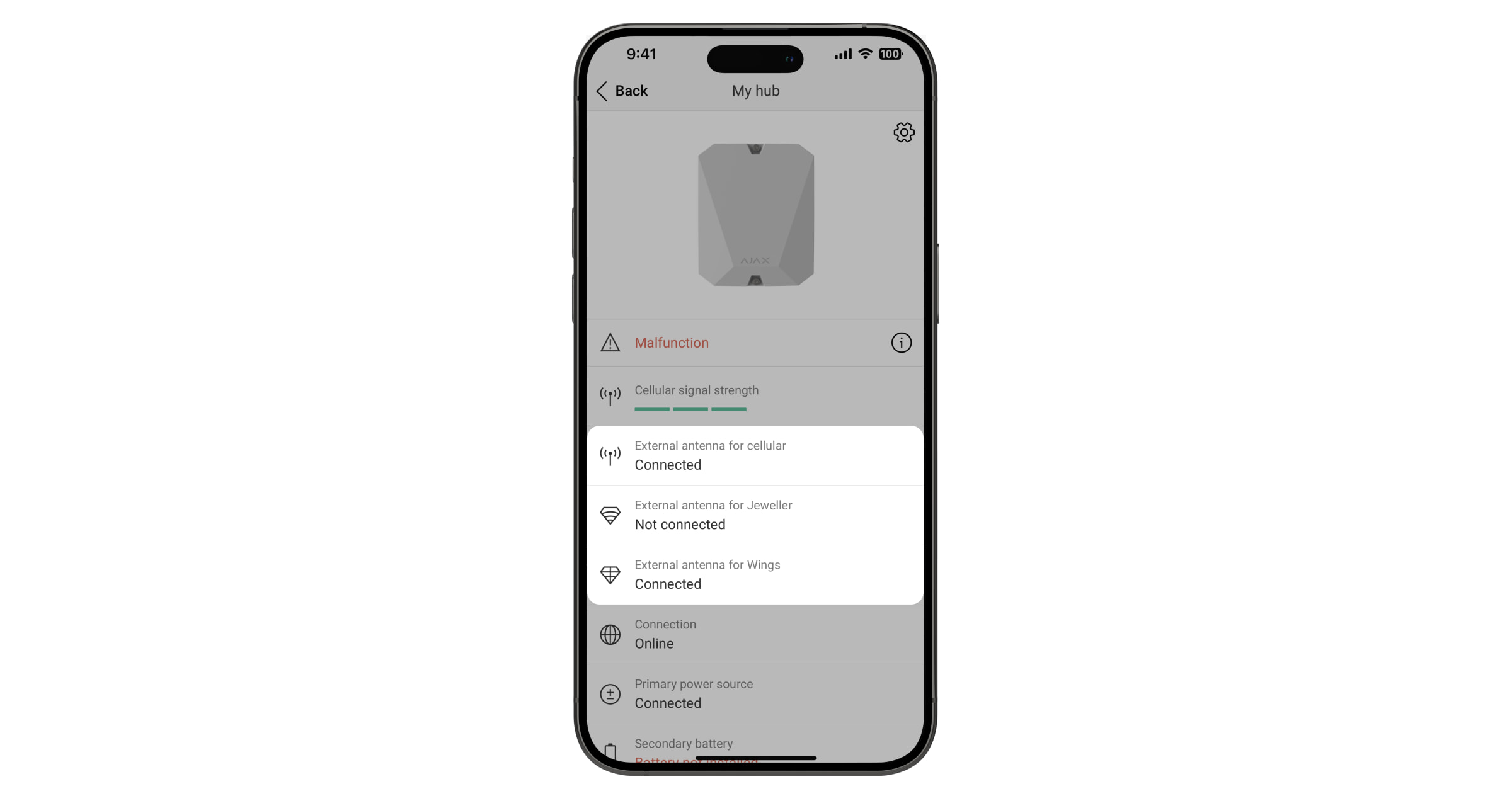
ExternalAntenna improves communication between the hub and connected devices or mobile network. It is useful when the Hub is installed in a safe, in a reinforced concrete room or in other places where the signal has to overcome obstacles. The antenna can be connected to the required Jeweller, Wings or Cellular connectors.
Choosing the installation location
When selecting the installation location for the antenna, factors affecting its performance must be taken into account:
Signal strength of the selected communication channel (Jeweller, Wings or Cellular).
Distance between the antenna and the hub. When using two or more antennas, the distance between them must be at least 60 cm.
Obstacles affecting the radio signal: walls, ceilings and large objects in the room.
Follow the installation recommendations when designing your Ajax system. The safety system must only be designed and installed by specialists. A list of recommended Ajax partners is available here.
Places where the antenna should not be installed
In rooms where the temperature and humidity exceed the permissible limits. This can damage the antenna.
In areas with low signal levels. This may cause loss of connection.
Close to metal objects and mirrors. Conductive objects may obscure the antenna.
Preparing for installation
Before installing the external antenna, make sure that:
The hub is compatible with the ExternalAntenna;
the hub has a stable 2-3 bar signal with the mobile network at the installation site;
all connected devices have a stable 2-3 bar signal at the installation site;
the cable length from the hub to the installation site is sufficient.
Cable layout
When preparing the cable routing, check the wiring and fire safety regulations for your region. Strictly comply with these standards and regulations. Practical advice on cable routing is available in this article.
Cable routing
Before installation, read carefully the section Selecting the installation site. Avoid deviations from the system design. Failure to follow the basic rules and recommendations in this manual may cause malfunctions. Learn more
Installation
Before installation, make sure that you have selected the optimum location for the device that meets the requirements of this manual.
Only a professional electrician should install the appliance.
How to install ExternalAntenna
Before installing the antenna, read the manual of the respective Hub.
Make sure that the hub is unplugged before installation.
Remove the front cover of the hub.
Identify the Jeweller, Wings or Cellular connectors on the circuit board.
Remove the isolation cap from the selected connector.
Connect the SMA (male) connector of the antenna to the SMA (female) connector of the board.
Switch on the hub. Close the housing of the hub. Remove the protective film from the pre-applied double-sided tape. Install the antenna at the selected location. Check the connection status in the app.
Status
The Hub statuses contain information about the connection status of the antenna. These statuses are available in the Ajax app:
Open the Devices tab.
Select the hub from the list.
If the ExternalAntenna is damaged, the system will notify the user and the CMS.
Maintenance
ExternalAntenna does not require maintenance.
Technical specifications All technical specifications
Compliance with standards
Warranty
The Ajax Systems Manufacturing limited company product warranty is valid for 2 years after purchase.
If the device fails to function properly, please contact Ajax Technical Support first. In most cases, technical problems can be resolved remotely.
Available for pickup at
Out of stock at
Added to compare
Reached count_product-product limit
Added to compare
Reached count_product-product limit
{"id":55850850124111,"title":"Default Title","option1":"Default Title","option2":null,"option3":null,"sku":"367305099","requires_shipping":true,"taxable":true,"featured_image":null,"available":true,"name":"AJAX Tag Contactless key fob for KeyPad Plus (3pcs) black","public_title":null,"options":["Default Title"],"price":1764,"weight":0,"compare_at_price":2250,"inventory_management":"shopify","barcode":"4820246099325","requires_selling_plan":false,"selling_plan_allocations":[],"quantity_rule":{"min":1,"max":null,"increment":1}}
AJAX Tag Contactless key fob for KeyPad Plus (3pcs) black
SKU: 367305099
€17,64€22,50
Unit price
Tag and Pass user manual
TagandPassare encrypted contactless access devices for managing the security modes of the Ajax system. They have the same functions and differ only in their body: Tag is a key fob, and Pass is a card.
Tag and Pass allow you to manage an object's security without an account, access to the Ajax app, or knowing the password - all it takes is activating a compatible keypad and putting the key fob or card to it. The security system or a specific group will be armed or disarmed.
To quickly and securely identify users, KeyPad Plus uses the DESFire® technology. DESFire® is based on the ISO 14443 international standard and combines 128-bit encryption and copy protection.
Tag and Pass usage is recorded in the events feed. The system administrator can at any time revoke or restrict the access rights of the contactless identification device through the Ajax app.
Tag and Pass can work with or without user binding, which affects the notification texts in Ajax app and SMS.
With user binding
Theusernameis displayed in the notifications and events feed
Without user binding
Thedevice nameis displayed in the notifications and events feed
Tag and Pass can work with several hubs at the same time. The maximum number of hubs in the device memory is 13. Keep in mind that you need to bind a Tag or Pass to each of the hubs separately through the Ajax app.
The maximum number of Tag and Pass devices connected to a hub depends on the hub model. At the same time, the Tag or Pass does not affect the total limit of devices on the hub.
Hub model
Number of Tag and Pass devices
Hub Plus
99
Hub 2
50
Superior Hub Hybrid (2G)/(4G)
50
Hub 2 Plus
200
One user can bind any number of Tag and Pass devices within the limit of contactless identification devices on the hub. Keep in mind that devices remain connected to the hub even after all keypads have been removed.
Sending events to the monitoring station
The Ajax security system can connect to the monitoring station and transmit events to the CMS viaSurGard (Contact-ID),SIA (DC-09), ADEMCO 685, and other proprietary protocols. A complete list of supported protocols isavailable here.
When a Tag or Pass is bound to a user, arm and disarm events will be sent to the monitoring station with the user ID. If the device is not bound with the user, the hub will send the event with the device identifier. You can find the device ID in theStatusmenu.
Adding to the system
The devices are incompatible with the hub type ofHub, third-party security central panels, andocBridge Plusand uartBridgeintegration modules. Pass and Tag only work with KeyPad Plus keyboards.
Before adding a device
Install the Ajaxapp. Create anaccount. Add a hub to the app and create at least one room.
Make sure that the hub is on and has access to the internet (via Ethernet cable, Wi-Fi, and/or mobile network). You can do this in the Ajax app or by looking at the hub logo on the front panel - the hub lights white or green when connected to the network.
Make sure the hub is not armed nor updates by looking at its status in the Ajax app.
Make sure a compatible keypad with DESFire® support is already connected to the hub.
If you want to bind a Tag or Pass to a user, make sure that the user's account has already been added to the hub.
Only a user or PRO with administrator rights can connect a device to the hub.
How to add a Tag or Pass to the system
Open the Ajax app. If your account has access to multiple hubs, select the one to which you want to add a Tag or Pass.
Go to theDevices tab.
Make sure thePass/Tag Readingfeature is enabled in at least one keypad settings.
ClickAdd Device.
From the drop-down menu, selectAdd Pass/Tag.
Specify the type (Tag or Pass), colour, device name, and name (if necessary).
ClickNext. After that, the hub will switch to the device registration mode.
Go to any compatible keypad withPass/Tag Readingenabled, activate it - the device will beep (if enabled in the settings), and the backlight will light up. Then press thedisarming key . The keypad will switch to the access device logging mode.
Put Tag or Pass with the wide side to the keypad reader for a few seconds. It is marked with wave icons on the body. Upon successful addition, you will receive a notification in the Ajax app.
If the connection fails, try again in 5 seconds. Please note that if the maximum number of Tag or Pass devices has already been added to the hub, you will receive a corresponding notification in the Ajax app when adding a new device.
Tag and Pass can work with several hubs at the same time. The maximum number of hubs is 13. Keep in mind that you need to bind devices to each of the hubs separately through the Ajax app.
If you try to bind a Tag or Pass to a hub that has already reached the hub limit (13 hubs are bound to them), you will receive a corresponding notification. To bind such a Tag or Pass to a new hub, you will need to reset it (all data from tag/pass will be erased).
Selection of security modes and groups that can be managed by this Tag or Pass.
The field is displayed and active if Tag or Pass is not associated with the user
Active
Allows you to temporarily disable Tag or Pass without removing the device from the system
User Guide
Opens the Tag and Pass User Manual in the Ajax app
Unpair device
Removes Tag or Pass and its settings from the system.
There are two options for removing: when Tag or Pass is placed nearby, or access to it is absent.
If Tag or Pass is nearby:
Start the device removal process.
Go to any compatible keypad and activate it.
Press the disarming key . The keypad will change to access devices removal mode.
Bring the Tag or Pass to the keypad reader. It is marked with wave icons on the body. Upon successful removal, you will receive a notification in the Ajax app.
When you delete a Tag or Pass in this way, they disappear from the list of hub devices in the application.
If Tag or Pass is not available:
Start the device removal process.
Select theDelete without pass/tagoption and follow the app's instructions.
In this case, the hub is not deleted from the Tag or Pass memory. To clear the device's memory, you will need to reset it (all data will be deleted from the device).
Binding a Tag or Pass to a user
When a Tag or Pass is linked to a user, it fully inherits the rights to manage the user's security modes. For example, if a user was able to manage only one group, then the bound Tag or Pass will have the right to manage only this group.
One user can bind any number of Tag or Pass devices within the limit of contactless identification devices connected to the hub.
User rights and permissions are stored in the hub. After being bound to a user, Tag and Pass represent the user in the system if devices are bound to the user. Therefore, when changing user rights, you do not need to make changes to the Tag or Pass settings - they are applied automatically.
To bind a Tag or Pass to a user, in the Ajax app:
Select the required hub if there are several hubs in your account.
Go to theDevices menu.
SelectPasses/Tags.
Select the required Tag or Pass.
Click on the to go to settings.
Select a user in the appropriate field.
ClickBackto save the settings.
When the user-to whom Tag or Pass is assigned-is deleted from the hub, the access device can not be used to manage security modes until not assigned to another user.
Temporarily deactivating a Tag or Pass
The Tag key fob or the Pass card can be temporarily disabled without removing them from the system. A deactivated card cannot be used to manage security modes.
If you try to change the security mode with a temporarily deactivated card or key fob more than 3 times, the keypad will be locked for the time set in the settings (if the setting is enabled), and corresponding notifications will be sent to the system users and to the security company monitoring station.
To temporarily deactivate a Tag or Pass, in the Ajax app:
Select the required hub if there are several hubs in your account.
Go to theDevices menu.
SelectPasses/Tags.
Select the required Tag or Pass.
Click on the to go to settings.
Disable theActiveoption.
ClickBackto save the settings.
To reactivate Tag or Pass, turn on theActiveoption.
Resetting a Tag or Pass
Up to 13 hubs can be bound to one Tag or Pass. As soon as this limit is reached, binding new hubs will only be possible after completely resetting the Tag or Pass.
Note that resetting will delete all settings and bindings of key fobs and cards. In this case, the reset Tag and Pass are only removed from the hub from which the reset was made. On other hubs, Tag or Pass are still displayed in the app, but they cannot be used to manage the security modes. These devices should be removed manually.
When protection against unauthorized access is enabled, 3 attempts to change the security mode with a card or key fob that has been reset in a row block the keypad. Users and a security company are instantly notified. The time of blocking is set in the device settings.
To reset a Tag or Pass, in the Ajax app:
Select the required hub if there are several hubs in your account.
Go to theDevices menu.
Select a compatible keypad from the device list.
Click on to go to settings.
Select thePass/Tag Resetmenu.
Go to the keypad with pass/tag reading enabled and activate it. Then press thedisarming key . The keypad will change to the access device formatting mode.
Put the Tag or Pass to the keypad reader. It is marked with wave icons on the body. Upon successful formatting, you will receive a notification in the Ajax app.
Use
The devices do not require additional installation or fastening. The Tag key fob is easy to carry with you thanks to a special hole on the body. You can hang the device on your wrist or around your neck, or attach it to the key ring. The Pass card has no holes in the body, but you can store it in your wallet or phone case.
If you store a Tag or Pass in your wallet, do not place other cards next to it, such as credit or travel cards. This may interfere with the correct operation of the device when attempting to disarm or arm the system.
To change the security mode:
Activate KeyPad Plus by swiping over it with your hand. The keypad will beep (if enabled in the settings), and the backlight will light up.
Put the Tag or Pass to the keypad reader. It is marked with wave icons on the body.
Change the security mode of the object or zone. Note that if theEasy armed mode changeoption is enabled in the keypad settings, you do not need to press the security mode change button. The security mode will change to the opposite after holding or tapping Tag or Pass.
Tag and Pass can participate in two-stage arming, but cannot be used as second-stage devices. The two-stage arming process using Tag or Pass is similar to arming with a personal or general keypad password.
{"id":55850837705039,"title":"Default Title","option1":"Default Title","option2":null,"option3":null,"sku":"367304863","requires_shipping":true,"taxable":true,"featured_image":null,"available":true,"name":"AJAX Tag Contactless key fob for KeyPad Plus (3pcs) white","public_title":null,"options":["Default Title"],"price":1764,"weight":0,"compare_at_price":2250,"inventory_management":"shopify","barcode":"4820246099356","requires_selling_plan":false,"selling_plan_allocations":[],"quantity_rule":{"min":1,"max":null,"increment":1}}
AJAX Tag Contactless key fob for KeyPad Plus (3pcs) white
SKU: 367304863
€17,64€22,50
Unit price
Tag and Pass user manual
TagandPassare encrypted contactless access devices for managing the security modes of the Ajax system. They have the same functions and differ only in their body: Tag is a key fob, and Pass is a card.
Tag and Pass allow you to manage an object's security without an account, access to the Ajax app, or knowing the password - all it takes is activating a compatible keypad and putting the key fob or card to it. The security system or a specific group will be armed or disarmed.
To quickly and securely identify users, KeyPad Plus uses the DESFire® technology. DESFire® is based on the ISO 14443 international standard and combines 128-bit encryption and copy protection.
Tag and Pass usage is recorded in the events feed. The system administrator can at any time revoke or restrict the access rights of the contactless identification device through the Ajax app.
Tag and Pass can work with or without user binding, which affects the notification texts in Ajax app and SMS.
With user binding
Theusernameis displayed in the notifications and events feed
Without user binding
Thedevice nameis displayed in the notifications and events feed
Tag and Pass can work with several hubs at the same time. The maximum number of hubs in the device memory is 13. Keep in mind that you need to bind a Tag or Pass to each of the hubs separately through the Ajax app.
The maximum number of Tag and Pass devices connected to a hub depends on the hub model. At the same time, the Tag or Pass does not affect the total limit of devices on the hub.
Hub model
Number of Tag and Pass devices
Hub Plus
99
Hub 2
50
Superior Hub Hybrid (2G)/(4G)
50
Hub 2 Plus
200
One user can bind any number of Tag and Pass devices within the limit of contactless identification devices on the hub. Keep in mind that devices remain connected to the hub even after all keypads have been removed.
Sending events to the monitoring station
The Ajax security system can connect to the monitoring station and transmit events to the CMS viaSurGard (Contact-ID),SIA (DC-09), ADEMCO 685, and other proprietary protocols. A complete list of supported protocols isavailable here.
When a Tag or Pass is bound to a user, arm and disarm events will be sent to the monitoring station with the user ID. If the device is not bound with the user, the hub will send the event with the device identifier. You can find the device ID in theStatusmenu.
Adding to the system
The devices are incompatible with the hub type ofHub, third-party security central panels, andocBridge Plusand uartBridgeintegration modules. Pass and Tag only work with KeyPad Plus keyboards.
Before adding a device
Install the Ajaxapp. Create anaccount. Add a hub to the app and create at least one room.
Make sure that the hub is on and has access to the internet (via Ethernet cable, Wi-Fi, and/or mobile network). You can do this in the Ajax app or by looking at the hub logo on the front panel - the hub lights white or green when connected to the network.
Make sure the hub is not armed nor updates by looking at its status in the Ajax app.
Make sure a compatible keypad with DESFire® support is already connected to the hub.
If you want to bind a Tag or Pass to a user, make sure that the user's account has already been added to the hub.
Only a user or PRO with administrator rights can connect a device to the hub.
How to add a Tag or Pass to the system
Open the Ajax app. If your account has access to multiple hubs, select the one to which you want to add a Tag or Pass.
Go to theDevices tab.
Make sure thePass/Tag Readingfeature is enabled in at least one keypad settings.
ClickAdd Device.
From the drop-down menu, selectAdd Pass/Tag.
Specify the type (Tag or Pass), colour, device name, and name (if necessary).
ClickNext. After that, the hub will switch to the device registration mode.
Go to any compatible keypad withPass/Tag Readingenabled, activate it - the device will beep (if enabled in the settings), and the backlight will light up. Then press thedisarming key . The keypad will switch to the access device logging mode.
Put Tag or Pass with the wide side to the keypad reader for a few seconds. It is marked with wave icons on the body. Upon successful addition, you will receive a notification in the Ajax app.
If the connection fails, try again in 5 seconds. Please note that if the maximum number of Tag or Pass devices has already been added to the hub, you will receive a corresponding notification in the Ajax app when adding a new device.
Tag and Pass can work with several hubs at the same time. The maximum number of hubs is 13. Keep in mind that you need to bind devices to each of the hubs separately through the Ajax app.
If you try to bind a Tag or Pass to a hub that has already reached the hub limit (13 hubs are bound to them), you will receive a corresponding notification. To bind such a Tag or Pass to a new hub, you will need to reset it (all data from tag/pass will be erased).
Selection of security modes and groups that can be managed by this Tag or Pass.
The field is displayed and active if Tag or Pass is not associated with the user
Active
Allows you to temporarily disable Tag or Pass without removing the device from the system
User Guide
Opens the Tag and Pass User Manual in the Ajax app
Unpair device
Removes Tag or Pass and its settings from the system.
There are two options for removing: when Tag or Pass is placed nearby, or access to it is absent.
If Tag or Pass is nearby:
Start the device removal process.
Go to any compatible keypad and activate it.
Press the disarming key . The keypad will change to access devices removal mode.
Bring the Tag or Pass to the keypad reader. It is marked with wave icons on the body. Upon successful removal, you will receive a notification in the Ajax app.
When you delete a Tag or Pass in this way, they disappear from the list of hub devices in the application.
If Tag or Pass is not available:
Start the device removal process.
Select theDelete without pass/tagoption and follow the app's instructions.
In this case, the hub is not deleted from the Tag or Pass memory. To clear the device's memory, you will need to reset it (all data will be deleted from the device).
Binding a Tag or Pass to a user
When a Tag or Pass is linked to a user, it fully inherits the rights to manage the user's security modes. For example, if a user was able to manage only one group, then the bound Tag or Pass will have the right to manage only this group.
One user can bind any number of Tag or Pass devices within the limit of contactless identification devices connected to the hub.
User rights and permissions are stored in the hub. After being bound to a user, Tag and Pass represent the user in the system if devices are bound to the user. Therefore, when changing user rights, you do not need to make changes to the Tag or Pass settings - they are applied automatically.
To bind a Tag or Pass to a user, in the Ajax app:
Select the required hub if there are several hubs in your account.
Go to theDevices menu.
SelectPasses/Tags.
Select the required Tag or Pass.
Click on the to go to settings.
Select a user in the appropriate field.
ClickBackto save the settings.
When the user-to whom Tag or Pass is assigned-is deleted from the hub, the access device can not be used to manage security modes until not assigned to another user.
Temporarily deactivating a Tag or Pass
The Tag key fob or the Pass card can be temporarily disabled without removing them from the system. A deactivated card cannot be used to manage security modes.
If you try to change the security mode with a temporarily deactivated card or key fob more than 3 times, the keypad will be locked for the time set in the settings (if the setting is enabled), and corresponding notifications will be sent to the system users and to the security company monitoring station.
To temporarily deactivate a Tag or Pass, in the Ajax app:
Select the required hub if there are several hubs in your account.
Go to theDevices menu.
SelectPasses/Tags.
Select the required Tag or Pass.
Click on the to go to settings.
Disable theActiveoption.
ClickBackto save the settings.
To reactivate Tag or Pass, turn on theActiveoption.
Resetting a Tag or Pass
Up to 13 hubs can be bound to one Tag or Pass. As soon as this limit is reached, binding new hubs will only be possible after completely resetting the Tag or Pass.
Note that resetting will delete all settings and bindings of key fobs and cards. In this case, the reset Tag and Pass are only removed from the hub from which the reset was made. On other hubs, Tag or Pass are still displayed in the app, but they cannot be used to manage the security modes. These devices should be removed manually.
When protection against unauthorized access is enabled, 3 attempts to change the security mode with a card or key fob that has been reset in a row block the keypad. Users and a security company are instantly notified. The time of blocking is set in the device settings.
To reset a Tag or Pass, in the Ajax app:
Select the required hub if there are several hubs in your account.
Go to theDevices menu.
Select a compatible keypad from the device list.
Click on to go to settings.
Select thePass/Tag Resetmenu.
Go to the keypad with pass/tag reading enabled and activate it. Then press thedisarming key . The keypad will change to the access device formatting mode.
Put the Tag or Pass to the keypad reader. It is marked with wave icons on the body. Upon successful formatting, you will receive a notification in the Ajax app.
Use
The devices do not require additional installation or fastening. The Tag key fob is easy to carry with you thanks to a special hole on the body. You can hang the device on your wrist or around your neck, or attach it to the key ring. The Pass card has no holes in the body, but you can store it in your wallet or phone case.
If you store a Tag or Pass in your wallet, do not place other cards next to it, such as credit or travel cards. This may interfere with the correct operation of the device when attempting to disarm or arm the system.
To change the security mode:
Activate KeyPad Plus by swiping over it with your hand. The keypad will beep (if enabled in the settings), and the backlight will light up.
Put the Tag or Pass to the keypad reader. It is marked with wave icons on the body.
Change the security mode of the object or zone. Note that if theEasy armed mode changeoption is enabled in the keypad settings, you do not need to press the security mode change button. The security mode will change to the opposite after holding or tapping Tag or Pass.
Tag and Pass can participate in two-stage arming, but cannot be used as second-stage devices. The two-stage arming process using Tag or Pass is similar to arming with a personal or general keypad password.
Ajax Pass Contactless card for KeyPad Plus (3pcs) black
SKU: 367308977
€17,64€22,50
Unit price
Tag and Pass user manual
TagandPassare encrypted contactless access devices for managing the security modes of the Ajax system. They have the same functions and differ only in their body: Tag is a key fob, and Pass is a card.
Tag and Pass allow you to manage an object's security without an account, access to the Ajax app, or knowing the password - all it takes is activating a compatible keypad and putting the key fob or card to it. The security system or a specific group will be armed or disarmed.
To quickly and securely identify users, KeyPad Plus uses the DESFire® technology. DESFire® is based on the ISO 14443 international standard and combines 128-bit encryption and copy protection.
Tag and Pass usage is recorded in the events feed. The system administrator can at any time revoke or restrict the access rights of the contactless identification device through the Ajax app.
Tag and Pass can work with or without user binding, which affects the notification texts in Ajax app and SMS.
With user binding
Theusernameis displayed in the notifications and events feed
Without user binding
Thedevice nameis displayed in the notifications and events feed
Tag and Pass can work with several hubs at the same time. The maximum number of hubs in the device memory is 13. Keep in mind that you need to bind a Tag or Pass to each of the hubs separately through the Ajax app.
The maximum number of Tag and Pass devices connected to a hub depends on the hub model. At the same time, the Tag or Pass does not affect the total limit of devices on the hub.
Hub model
Number of Tag and Pass devices
Hub Plus
99
Hub 2
50
Superior Hub Hybrid (2G)/(4G)
50
Hub 2 Plus
200
One user can bind any number of Tag and Pass devices within the limit of contactless identification devices on the hub. Keep in mind that devices remain connected to the hub even after all keypads have been removed.
Sending events to the monitoring station
The Ajax security system can connect to the monitoring station and transmit events to the CMS viaSurGard (Contact-ID),SIA (DC-09), ADEMCO 685, and other proprietary protocols. A complete list of supported protocols isavailable here.
When a Tag or Pass is bound to a user, arm and disarm events will be sent to the monitoring station with the user ID. If the device is not bound with the user, the hub will send the event with the device identifier. You can find the device ID in theStatusmenu.
Adding to the system
The devices are incompatible with the hub type ofHub, third-party security central panels, andocBridge Plusand uartBridgeintegration modules. Pass and Tag only work with KeyPad Plus keyboards.
Before adding a device
Install the Ajaxapp. Create anaccount. Add a hub to the app and create at least one room.
Make sure that the hub is on and has access to the internet (via Ethernet cable, Wi-Fi, and/or mobile network). You can do this in the Ajax app or by looking at the hub logo on the front panel - the hub lights white or green when connected to the network.
Make sure the hub is not armed nor updates by looking at its status in the Ajax app.
Make sure a compatible keypad with DESFire® support is already connected to the hub.
If you want to bind a Tag or Pass to a user, make sure that the user's account has already been added to the hub.
Only a user or PRO with administrator rights can connect a device to the hub.
How to add a Tag or Pass to the system
Open the Ajax app. If your account has access to multiple hubs, select the one to which you want to add a Tag or Pass.
Go to theDevices tab.
Make sure thePass/Tag Readingfeature is enabled in at least one keypad settings.
ClickAdd Device.
From the drop-down menu, selectAdd Pass/Tag.
Specify the type (Tag or Pass), colour, device name, and name (if necessary).
ClickNext. After that, the hub will switch to the device registration mode.
Go to any compatible keypad withPass/Tag Readingenabled, activate it - the device will beep (if enabled in the settings), and the backlight will light up. Then press thedisarming key . The keypad will switch to the access device logging mode.
Put Tag or Pass with the wide side to the keypad reader for a few seconds. It is marked with wave icons on the body. Upon successful addition, you will receive a notification in the Ajax app.
If the connection fails, try again in 5 seconds. Please note that if the maximum number of Tag or Pass devices has already been added to the hub, you will receive a corresponding notification in the Ajax app when adding a new device.
Tag and Pass can work with several hubs at the same time. The maximum number of hubs is 13. Keep in mind that you need to bind devices to each of the hubs separately through the Ajax app.
If you try to bind a Tag or Pass to a hub that has already reached the hub limit (13 hubs are bound to them), you will receive a corresponding notification. To bind such a Tag or Pass to a new hub, you will need to reset it (all data from tag/pass will be erased).
Selection of security modes and groups that can be managed by this Tag or Pass.
The field is displayed and active if Tag or Pass is not associated with the user
Active
Allows you to temporarily disable Tag or Pass without removing the device from the system
User Guide
Opens the Tag and Pass User Manual in the Ajax app
Unpair device
Removes Tag or Pass and its settings from the system.
There are two options for removing: when Tag or Pass is placed nearby, or access to it is absent.
If Tag or Pass is nearby:
Start the device removal process.
Go to any compatible keypad and activate it.
Press the disarming key . The keypad will change to access devices removal mode.
Bring the Tag or Pass to the keypad reader. It is marked with wave icons on the body. Upon successful removal, you will receive a notification in the Ajax app.
When you delete a Tag or Pass in this way, they disappear from the list of hub devices in the application.
If Tag or Pass is not available:
Start the device removal process.
Select theDelete without pass/tagoption and follow the app's instructions.
In this case, the hub is not deleted from the Tag or Pass memory. To clear the device's memory, you will need to reset it (all data will be deleted from the device).
Binding a Tag or Pass to a user
When a Tag or Pass is linked to a user, it fully inherits the rights to manage the user's security modes. For example, if a user was able to manage only one group, then the bound Tag or Pass will have the right to manage only this group.
One user can bind any number of Tag or Pass devices within the limit of contactless identification devices connected to the hub.
User rights and permissions are stored in the hub. After being bound to a user, Tag and Pass represent the user in the system if devices are bound to the user. Therefore, when changing user rights, you do not need to make changes to the Tag or Pass settings - they are applied automatically.
To bind a Tag or Pass to a user, in the Ajax app:
Select the required hub if there are several hubs in your account.
Go to theDevices menu.
SelectPasses/Tags.
Select the required Tag or Pass.
Click on the to go to settings.
Select a user in the appropriate field.
ClickBackto save the settings.
When the user-to whom Tag or Pass is assigned-is deleted from the hub, the access device can not be used to manage security modes until not assigned to another user.
Temporarily deactivating a Tag or Pass
The Tag key fob or the Pass card can be temporarily disabled without removing them from the system. A deactivated card cannot be used to manage security modes.
If you try to change the security mode with a temporarily deactivated card or key fob more than 3 times, the keypad will be locked for the time set in the settings (if the setting is enabled), and corresponding notifications will be sent to the system users and to the security company monitoring station.
To temporarily deactivate a Tag or Pass, in the Ajax app:
Select the required hub if there are several hubs in your account.
Go to theDevices menu.
SelectPasses/Tags.
Select the required Tag or Pass.
Click on the to go to settings.
Disable theActiveoption.
ClickBackto save the settings.
To reactivate Tag or Pass, turn on theActiveoption.
Resetting a Tag or Pass
Up to 13 hubs can be bound to one Tag or Pass. As soon as this limit is reached, binding new hubs will only be possible after completely resetting the Tag or Pass.
Note that resetting will delete all settings and bindings of key fobs and cards. In this case, the reset Tag and Pass are only removed from the hub from which the reset was made. On other hubs, Tag or Pass are still displayed in the app, but they cannot be used to manage the security modes. These devices should be removed manually.
When protection against unauthorized access is enabled, 3 attempts to change the security mode with a card or key fob that has been reset in a row block the keypad. Users and a security company are instantly notified. The time of blocking is set in the device settings.
To reset a Tag or Pass, in the Ajax app:
Select the required hub if there are several hubs in your account.
Go to theDevices menu.
Select a compatible keypad from the device list.
Click on to go to settings.
Select thePass/Tag Resetmenu.
Go to the keypad with pass/tag reading enabled and activate it. Then press thedisarming key . The keypad will change to the access device formatting mode.
Put the Tag or Pass to the keypad reader. It is marked with wave icons on the body. Upon successful formatting, you will receive a notification in the Ajax app.
Use
The devices do not require additional installation or fastening. The Tag key fob is easy to carry with you thanks to a special hole on the body. You can hang the device on your wrist or around your neck, or attach it to the key ring. The Pass card has no holes in the body, but you can store it in your wallet or phone case.
If you store a Tag or Pass in your wallet, do not place other cards next to it, such as credit or travel cards. This may interfere with the correct operation of the device when attempting to disarm or arm the system.
To change the security mode:
Activate KeyPad Plus by swiping over it with your hand. The keypad will beep (if enabled in the settings), and the backlight will light up.
Put the Tag or Pass to the keypad reader. It is marked with wave icons on the body.
Change the security mode of the object or zone. Note that if theEasy armed mode changeoption is enabled in the keypad settings, you do not need to press the security mode change button. The security mode will change to the opposite after holding or tapping Tag or Pass.
Tag and Pass can participate in two-stage arming, but cannot be used as second-stage devices. The two-stage arming process using Tag or Pass is similar to arming with a personal or general keypad password.
Ajax Pass Contactless card for KeyPad Plus (3pcs) white
SKU: 367308977
€17,64€22,50
Unit price
Tag and Pass user manual
TagandPassare encrypted contactless access devices for managing the security modes of the Ajax system. They have the same functions and differ only in their body: Tag is a key fob, and Pass is a card.
Tag and Pass allow you to manage an object's security without an account, access to the Ajax app, or knowing the password - all it takes is activating a compatible keypad and putting the key fob or card to it. The security system or a specific group will be armed or disarmed.
To quickly and securely identify users, KeyPad Plus uses the DESFire® technology. DESFire® is based on the ISO 14443 international standard and combines 128-bit encryption and copy protection.
Tag and Pass usage is recorded in the events feed. The system administrator can at any time revoke or restrict the access rights of the contactless identification device through the Ajax app.
Tag and Pass can work with or without user binding, which affects the notification texts in Ajax app and SMS.
With user binding
Theusernameis displayed in the notifications and events feed
Without user binding
Thedevice nameis displayed in the notifications and events feed
Tag and Pass can work with several hubs at the same time. The maximum number of hubs in the device memory is 13. Keep in mind that you need to bind a Tag or Pass to each of the hubs separately through the Ajax app.
The maximum number of Tag and Pass devices connected to a hub depends on the hub model. At the same time, the Tag or Pass does not affect the total limit of devices on the hub.
Hub model
Number of Tag and Pass devices
Hub Plus
99
Hub 2
50
Superior Hub Hybrid (2G)/(4G)
50
Hub 2 Plus
200
One user can bind any number of Tag and Pass devices within the limit of contactless identification devices on the hub. Keep in mind that devices remain connected to the hub even after all keypads have been removed.
Sending events to the monitoring station
The Ajax security system can connect to the monitoring station and transmit events to the CMS viaSurGard (Contact-ID),SIA (DC-09), ADEMCO 685, and other proprietary protocols. A complete list of supported protocols isavailable here.
When a Tag or Pass is bound to a user, arm and disarm events will be sent to the monitoring station with the user ID. If the device is not bound with the user, the hub will send the event with the device identifier. You can find the device ID in theStatusmenu.
Adding to the system
The devices are incompatible with the hub type ofHub, third-party security central panels, andocBridge Plusand uartBridgeintegration modules. Pass and Tag only work with KeyPad Plus keyboards.
Before adding a device
Install the Ajaxapp. Create anaccount. Add a hub to the app and create at least one room.
Make sure that the hub is on and has access to the internet (via Ethernet cable, Wi-Fi, and/or mobile network). You can do this in the Ajax app or by looking at the hub logo on the front panel - the hub lights white or green when connected to the network.
Make sure the hub is not armed nor updates by looking at its status in the Ajax app.
Make sure a compatible keypad with DESFire® support is already connected to the hub.
If you want to bind a Tag or Pass to a user, make sure that the user's account has already been added to the hub.
Only a user or PRO with administrator rights can connect a device to the hub.
How to add a Tag or Pass to the system
Open the Ajax app. If your account has access to multiple hubs, select the one to which you want to add a Tag or Pass.
Go to theDevices tab.
Make sure thePass/Tag Readingfeature is enabled in at least one keypad settings.
ClickAdd Device.
From the drop-down menu, selectAdd Pass/Tag.
Specify the type (Tag or Pass), colour, device name, and name (if necessary).
ClickNext. After that, the hub will switch to the device registration mode.
Go to any compatible keypad withPass/Tag Readingenabled, activate it - the device will beep (if enabled in the settings), and the backlight will light up. Then press thedisarming key . The keypad will switch to the access device logging mode.
Put Tag or Pass with the wide side to the keypad reader for a few seconds. It is marked with wave icons on the body. Upon successful addition, you will receive a notification in the Ajax app.
If the connection fails, try again in 5 seconds. Please note that if the maximum number of Tag or Pass devices has already been added to the hub, you will receive a corresponding notification in the Ajax app when adding a new device.
Tag and Pass can work with several hubs at the same time. The maximum number of hubs is 13. Keep in mind that you need to bind devices to each of the hubs separately through the Ajax app.
If you try to bind a Tag or Pass to a hub that has already reached the hub limit (13 hubs are bound to them), you will receive a corresponding notification. To bind such a Tag or Pass to a new hub, you will need to reset it (all data from tag/pass will be erased).
Selection of security modes and groups that can be managed by this Tag or Pass.
The field is displayed and active if Tag or Pass is not associated with the user
Active
Allows you to temporarily disable Tag or Pass without removing the device from the system
User Guide
Opens the Tag and Pass User Manual in the Ajax app
Unpair device
Removes Tag or Pass and its settings from the system.
There are two options for removing: when Tag or Pass is placed nearby, or access to it is absent.
If Tag or Pass is nearby:
Start the device removal process.
Go to any compatible keypad and activate it.
Press the disarming key . The keypad will change to access devices removal mode.
Bring the Tag or Pass to the keypad reader. It is marked with wave icons on the body. Upon successful removal, you will receive a notification in the Ajax app.
When you delete a Tag or Pass in this way, they disappear from the list of hub devices in the application.
If Tag or Pass is not available:
Start the device removal process.
Select theDelete without pass/tagoption and follow the app's instructions.
In this case, the hub is not deleted from the Tag or Pass memory. To clear the device's memory, you will need to reset it (all data will be deleted from the device).
Binding a Tag or Pass to a user
When a Tag or Pass is linked to a user, it fully inherits the rights to manage the user's security modes. For example, if a user was able to manage only one group, then the bound Tag or Pass will have the right to manage only this group.
One user can bind any number of Tag or Pass devices within the limit of contactless identification devices connected to the hub.
User rights and permissions are stored in the hub. After being bound to a user, Tag and Pass represent the user in the system if devices are bound to the user. Therefore, when changing user rights, you do not need to make changes to the Tag or Pass settings - they are applied automatically.
To bind a Tag or Pass to a user, in the Ajax app:
Select the required hub if there are several hubs in your account.
Go to theDevices menu.
SelectPasses/Tags.
Select the required Tag or Pass.
Click on the to go to settings.
Select a user in the appropriate field.
ClickBackto save the settings.
When the user-to whom Tag or Pass is assigned-is deleted from the hub, the access device can not be used to manage security modes until not assigned to another user.
Temporarily deactivating a Tag or Pass
The Tag key fob or the Pass card can be temporarily disabled without removing them from the system. A deactivated card cannot be used to manage security modes.
If you try to change the security mode with a temporarily deactivated card or key fob more than 3 times, the keypad will be locked for the time set in the settings (if the setting is enabled), and corresponding notifications will be sent to the system users and to the security company monitoring station.
To temporarily deactivate a Tag or Pass, in the Ajax app:
Select the required hub if there are several hubs in your account.
Go to theDevices menu.
SelectPasses/Tags.
Select the required Tag or Pass.
Click on the to go to settings.
Disable theActiveoption.
ClickBackto save the settings.
To reactivate Tag or Pass, turn on theActiveoption.
Resetting a Tag or Pass
Up to 13 hubs can be bound to one Tag or Pass. As soon as this limit is reached, binding new hubs will only be possible after completely resetting the Tag or Pass.
Note that resetting will delete all settings and bindings of key fobs and cards. In this case, the reset Tag and Pass are only removed from the hub from which the reset was made. On other hubs, Tag or Pass are still displayed in the app, but they cannot be used to manage the security modes. These devices should be removed manually.
When protection against unauthorized access is enabled, 3 attempts to change the security mode with a card or key fob that has been reset in a row block the keypad. Users and a security company are instantly notified. The time of blocking is set in the device settings.
To reset a Tag or Pass, in the Ajax app:
Select the required hub if there are several hubs in your account.
Go to theDevices menu.
Select a compatible keypad from the device list.
Click on to go to settings.
Select thePass/Tag Resetmenu.
Go to the keypad with pass/tag reading enabled and activate it. Then press thedisarming key . The keypad will change to the access device formatting mode.
Put the Tag or Pass to the keypad reader. It is marked with wave icons on the body. Upon successful formatting, you will receive a notification in the Ajax app.
Use
The devices do not require additional installation or fastening. The Tag key fob is easy to carry with you thanks to a special hole on the body. You can hang the device on your wrist or around your neck, or attach it to the key ring. The Pass card has no holes in the body, but you can store it in your wallet or phone case.
If you store a Tag or Pass in your wallet, do not place other cards next to it, such as credit or travel cards. This may interfere with the correct operation of the device when attempting to disarm or arm the system.
To change the security mode:
Activate KeyPad Plus by swiping over it with your hand. The keypad will beep (if enabled in the settings), and the backlight will light up.
Put the Tag or Pass to the keypad reader. It is marked with wave icons on the body.
Change the security mode of the object or zone. Note that if theEasy armed mode changeoption is enabled in the keypad settings, you do not need to press the security mode change button. The security mode will change to the opposite after holding or tapping Tag or Pass.
Tag and Pass can participate in two-stage arming, but cannot be used as second-stage devices. The two-stage arming process using Tag or Pass is similar to arming with a personal or general keypad password.
Mounting bracket for fixing the button to the surface
Key features Button fixing
Place the holder where the button is easily accessible.
Quick installation and removal of the button
The button is attached to the holder and removed in one movement. No tools or time wasted.
Housing Material Plastic
Dimensions 47,1 × 37,9 × 14,2 mm
Weight 3,5 g
Operating temperature range -10 °C to +40 °C
Colours White
Kit Holder Installation kit Quick Start Guide
Available for pickup at
Out of stock at
Added to compare
Reached count_product-product limit
Added to compare
Reached count_product-product limit
{"id":55850866901327,"title":"Default Title","option1":"Default Title","option2":null,"option3":null,"sku":"367311695","requires_shipping":true,"taxable":true,"featured_image":null,"available":true,"name":"Ajax Tag Contactless key fob for KeyPad Plus 1 gb black","public_title":null,"options":["Default Title"],"price":470,"weight":0,"compare_at_price":600,"inventory_management":"shopify","barcode":null,"requires_selling_plan":false,"selling_plan_allocations":[],"quantity_rule":{"min":1,"max":null,"increment":1}}
Ajax Tag Contactless key fob for KeyPad Plus 1 gb black
SKU: 367311695
€4,70€6,00
Unit price
Tag and Pass user manual
TagandPassare encrypted contactless access devices for managing the security modes of the Ajax system. They have the same functions and differ only in their body: Tag is a key fob, and Pass is a card.
Tag and Pass allow you to manage an object's security without an account, access to the Ajax app, or knowing the password - all it takes is activating a compatible keypad and putting the key fob or card to it. The security system or a specific group will be armed or disarmed.
To quickly and securely identify users, KeyPad Plus uses the DESFire® technology. DESFire® is based on the ISO 14443 international standard and combines 128-bit encryption and copy protection.
Tag and Pass usage is recorded in the events feed. The system administrator can at any time revoke or restrict the access rights of the contactless identification device through the Ajax app.
Tag and Pass can work with or without user binding, which affects the notification texts in Ajax app and SMS.
With user binding
Theusernameis displayed in the notifications and events feed
Without user binding
Thedevice nameis displayed in the notifications and events feed
Tag and Pass can work with several hubs at the same time. The maximum number of hubs in the device memory is 13. Keep in mind that you need to bind a Tag or Pass to each of the hubs separately through the Ajax app.
The maximum number of Tag and Pass devices connected to a hub depends on the hub model. At the same time, the Tag or Pass does not affect the total limit of devices on the hub.
Hub model
Number of Tag and Pass devices
Hub Plus
99
Hub 2
50
Superior Hub Hybrid (2G)/(4G)
50
Hub 2 Plus
200
One user can bind any number of Tag and Pass devices within the limit of contactless identification devices on the hub. Keep in mind that devices remain connected to the hub even after all keypads have been removed.
Sending events to the monitoring station
The Ajax security system can connect to the monitoring station and transmit events to the CMS viaSurGard (Contact-ID),SIA (DC-09), ADEMCO 685, and other proprietary protocols. A complete list of supported protocols isavailable here.
When a Tag or Pass is bound to a user, arm and disarm events will be sent to the monitoring station with the user ID. If the device is not bound with the user, the hub will send the event with the device identifier. You can find the device ID in theStatusmenu.
Adding to the system
The devices are incompatible with the hub type ofHub, third-party security central panels, andocBridge Plusand uartBridgeintegration modules. Pass and Tag only work with KeyPad Plus keyboards.
Before adding a device
Install the Ajaxapp. Create anaccount. Add a hub to the app and create at least one room.
Make sure that the hub is on and has access to the internet (via Ethernet cable, Wi-Fi, and/or mobile network). You can do this in the Ajax app or by looking at the hub logo on the front panel - the hub lights white or green when connected to the network.
Make sure the hub is not armed nor updates by looking at its status in the Ajax app.
Make sure a compatible keypad with DESFire® support is already connected to the hub.
If you want to bind a Tag or Pass to a user, make sure that the user's account has already been added to the hub.
Only a user or PRO with administrator rights can connect a device to the hub.
How to add a Tag or Pass to the system
Open the Ajax app. If your account has access to multiple hubs, select the one to which you want to add a Tag or Pass.
Go to theDevices tab.
Make sure thePass/Tag Readingfeature is enabled in at least one keypad settings.
ClickAdd Device.
From the drop-down menu, selectAdd Pass/Tag.
Specify the type (Tag or Pass), colour, device name, and name (if necessary).
ClickNext. After that, the hub will switch to the device registration mode.
Go to any compatible keypad withPass/Tag Readingenabled, activate it - the device will beep (if enabled in the settings), and the backlight will light up. Then press thedisarming key . The keypad will switch to the access device logging mode.
Put Tag or Pass with the wide side to the keypad reader for a few seconds. It is marked with wave icons on the body. Upon successful addition, you will receive a notification in the Ajax app.
If the connection fails, try again in 5 seconds. Please note that if the maximum number of Tag or Pass devices has already been added to the hub, you will receive a corresponding notification in the Ajax app when adding a new device.
Tag and Pass can work with several hubs at the same time. The maximum number of hubs is 13. Keep in mind that you need to bind devices to each of the hubs separately through the Ajax app.
If you try to bind a Tag or Pass to a hub that has already reached the hub limit (13 hubs are bound to them), you will receive a corresponding notification. To bind such a Tag or Pass to a new hub, you will need to reset it (all data from tag/pass will be erased).
Selection of security modes and groups that can be managed by this Tag or Pass.
The field is displayed and active if Tag or Pass is not associated with the user
Active
Allows you to temporarily disable Tag or Pass without removing the device from the system
User Guide
Opens the Tag and Pass User Manual in the Ajax app
Unpair device
Removes Tag or Pass and its settings from the system.
There are two options for removing: when Tag or Pass is placed nearby, or access to it is absent.
If Tag or Pass is nearby:
Start the device removal process.
Go to any compatible keypad and activate it.
Press the disarming key . The keypad will change to access devices removal mode.
Bring the Tag or Pass to the keypad reader. It is marked with wave icons on the body. Upon successful removal, you will receive a notification in the Ajax app.
When you delete a Tag or Pass in this way, they disappear from the list of hub devices in the application.
If Tag or Pass is not available:
Start the device removal process.
Select theDelete without pass/tagoption and follow the app's instructions.
In this case, the hub is not deleted from the Tag or Pass memory. To clear the device's memory, you will need to reset it (all data will be deleted from the device).
Binding a Tag or Pass to a user
When a Tag or Pass is linked to a user, it fully inherits the rights to manage the user's security modes. For example, if a user was able to manage only one group, then the bound Tag or Pass will have the right to manage only this group.
One user can bind any number of Tag or Pass devices within the limit of contactless identification devices connected to the hub.
User rights and permissions are stored in the hub. After being bound to a user, Tag and Pass represent the user in the system if devices are bound to the user. Therefore, when changing user rights, you do not need to make changes to the Tag or Pass settings - they are applied automatically.
To bind a Tag or Pass to a user, in the Ajax app:
Select the required hub if there are several hubs in your account.
Go to theDevices menu.
SelectPasses/Tags.
Select the required Tag or Pass.
Click on the to go to settings.
Select a user in the appropriate field.
ClickBackto save the settings.
When the user-to whom Tag or Pass is assigned-is deleted from the hub, the access device can not be used to manage security modes until not assigned to another user.
Temporarily deactivating a Tag or Pass
The Tag key fob or the Pass card can be temporarily disabled without removing them from the system. A deactivated card cannot be used to manage security modes.
If you try to change the security mode with a temporarily deactivated card or key fob more than 3 times, the keypad will be locked for the time set in the settings (if the setting is enabled), and corresponding notifications will be sent to the system users and to the security company monitoring station.
To temporarily deactivate a Tag or Pass, in the Ajax app:
Select the required hub if there are several hubs in your account.
Go to theDevices menu.
SelectPasses/Tags.
Select the required Tag or Pass.
Click on the to go to settings.
Disable theActiveoption.
ClickBackto save the settings.
To reactivate Tag or Pass, turn on theActiveoption.
Resetting a Tag or Pass
Up to 13 hubs can be bound to one Tag or Pass. As soon as this limit is reached, binding new hubs will only be possible after completely resetting the Tag or Pass.
Note that resetting will delete all settings and bindings of key fobs and cards. In this case, the reset Tag and Pass are only removed from the hub from which the reset was made. On other hubs, Tag or Pass are still displayed in the app, but they cannot be used to manage the security modes. These devices should be removed manually.
When protection against unauthorized access is enabled, 3 attempts to change the security mode with a card or key fob that has been reset in a row block the keypad. Users and a security company are instantly notified. The time of blocking is set in the device settings.
To reset a Tag or Pass, in the Ajax app:
Select the required hub if there are several hubs in your account.
Go to theDevices menu.
Select a compatible keypad from the device list.
Click on to go to settings.
Select thePass/Tag Resetmenu.
Go to the keypad with pass/tag reading enabled and activate it. Then press thedisarming key . The keypad will change to the access device formatting mode.
Put the Tag or Pass to the keypad reader. It is marked with wave icons on the body. Upon successful formatting, you will receive a notification in the Ajax app.
Use
The devices do not require additional installation or fastening. The Tag key fob is easy to carry with you thanks to a special hole on the body. You can hang the device on your wrist or around your neck, or attach it to the key ring. The Pass card has no holes in the body, but you can store it in your wallet or phone case.
If you store a Tag or Pass in your wallet, do not place other cards next to it, such as credit or travel cards. This may interfere with the correct operation of the device when attempting to disarm or arm the system.
To change the security mode:
Activate KeyPad Plus by swiping over it with your hand. The keypad will beep (if enabled in the settings), and the backlight will light up.
Put the Tag or Pass to the keypad reader. It is marked with wave icons on the body.
Change the security mode of the object or zone. Note that if theEasy armed mode changeoption is enabled in the keypad settings, you do not need to press the security mode change button. The security mode will change to the opposite after holding or tapping Tag or Pass.
Tag and Pass can participate in two-stage arming, but cannot be used as second-stage devices. The two-stage arming process using Tag or Pass is similar to arming with a personal or general keypad password.
{"id":55850861625679,"title":"Default Title","option1":"Default Title","option2":null,"option3":null,"sku":"367311694","requires_shipping":true,"taxable":true,"featured_image":null,"available":true,"name":"Ajax Tag Contactless key fob for KeyPad Plus 1 gb white","public_title":null,"options":["Default Title"],"price":470,"weight":0,"compare_at_price":600,"inventory_management":"shopify","barcode":null,"requires_selling_plan":false,"selling_plan_allocations":[],"quantity_rule":{"min":1,"max":null,"increment":1}}
Ajax Tag Contactless key fob for KeyPad Plus 1 gb white
SKU: 367311694
€4,70€6,00
Unit price
Tag and Pass user manual
TagandPassare encrypted contactless access devices for managing the security modes of the Ajax system. They have the same functions and differ only in their body: Tag is a key fob, and Pass is a card.
Tag and Pass allow you to manage an object's security without an account, access to the Ajax app, or knowing the password - all it takes is activating a compatible keypad and putting the key fob or card to it. The security system or a specific group will be armed or disarmed.
To quickly and securely identify users, KeyPad Plus uses the DESFire® technology. DESFire® is based on the ISO 14443 international standard and combines 128-bit encryption and copy protection.
Tag and Pass usage is recorded in the events feed. The system administrator can at any time revoke or restrict the access rights of the contactless identification device through the Ajax app.
Tag and Pass can work with or without user binding, which affects the notification texts in Ajax app and SMS.
With user binding
Theusernameis displayed in the notifications and events feed
Without user binding
Thedevice nameis displayed in the notifications and events feed
Tag and Pass can work with several hubs at the same time. The maximum number of hubs in the device memory is 13. Keep in mind that you need to bind a Tag or Pass to each of the hubs separately through the Ajax app.
The maximum number of Tag and Pass devices connected to a hub depends on the hub model. At the same time, the Tag or Pass does not affect the total limit of devices on the hub.
Hub model
Number of Tag and Pass devices
Hub Plus
99
Hub 2
50
Superior Hub Hybrid (2G)/(4G)
50
Hub 2 Plus
200
One user can bind any number of Tag and Pass devices within the limit of contactless identification devices on the hub. Keep in mind that devices remain connected to the hub even after all keypads have been removed.
Sending events to the monitoring station
The Ajax security system can connect to the monitoring station and transmit events to the CMS viaSurGard (Contact-ID),SIA (DC-09), ADEMCO 685, and other proprietary protocols. A complete list of supported protocols isavailable here.
When a Tag or Pass is bound to a user, arm and disarm events will be sent to the monitoring station with the user ID. If the device is not bound with the user, the hub will send the event with the device identifier. You can find the device ID in theStatusmenu.
Adding to the system
The devices are incompatible with the hub type ofHub, third-party security central panels, andocBridge Plusand uartBridgeintegration modules. Pass and Tag only work with KeyPad Plus keyboards.
Before adding a device
Install the Ajaxapp. Create anaccount. Add a hub to the app and create at least one room.
Make sure that the hub is on and has access to the internet (via Ethernet cable, Wi-Fi, and/or mobile network). You can do this in the Ajax app or by looking at the hub logo on the front panel - the hub lights white or green when connected to the network.
Make sure the hub is not armed nor updates by looking at its status in the Ajax app.
Make sure a compatible keypad with DESFire® support is already connected to the hub.
If you want to bind a Tag or Pass to a user, make sure that the user's account has already been added to the hub.
Only a user or PRO with administrator rights can connect a device to the hub.
How to add a Tag or Pass to the system
Open the Ajax app. If your account has access to multiple hubs, select the one to which you want to add a Tag or Pass.
Go to theDevices tab.
Make sure thePass/Tag Readingfeature is enabled in at least one keypad settings.
ClickAdd Device.
From the drop-down menu, selectAdd Pass/Tag.
Specify the type (Tag or Pass), colour, device name, and name (if necessary).
ClickNext. After that, the hub will switch to the device registration mode.
Go to any compatible keypad withPass/Tag Readingenabled, activate it - the device will beep (if enabled in the settings), and the backlight will light up. Then press thedisarming key . The keypad will switch to the access device logging mode.
Put Tag or Pass with the wide side to the keypad reader for a few seconds. It is marked with wave icons on the body. Upon successful addition, you will receive a notification in the Ajax app.
If the connection fails, try again in 5 seconds. Please note that if the maximum number of Tag or Pass devices has already been added to the hub, you will receive a corresponding notification in the Ajax app when adding a new device.
Tag and Pass can work with several hubs at the same time. The maximum number of hubs is 13. Keep in mind that you need to bind devices to each of the hubs separately through the Ajax app.
If you try to bind a Tag or Pass to a hub that has already reached the hub limit (13 hubs are bound to them), you will receive a corresponding notification. To bind such a Tag or Pass to a new hub, you will need to reset it (all data from tag/pass will be erased).
Selection of security modes and groups that can be managed by this Tag or Pass.
The field is displayed and active if Tag or Pass is not associated with the user
Active
Allows you to temporarily disable Tag or Pass without removing the device from the system
User Guide
Opens the Tag and Pass User Manual in the Ajax app
Unpair device
Removes Tag or Pass and its settings from the system.
There are two options for removing: when Tag or Pass is placed nearby, or access to it is absent.
If Tag or Pass is nearby:
Start the device removal process.
Go to any compatible keypad and activate it.
Press the disarming key . The keypad will change to access devices removal mode.
Bring the Tag or Pass to the keypad reader. It is marked with wave icons on the body. Upon successful removal, you will receive a notification in the Ajax app.
When you delete a Tag or Pass in this way, they disappear from the list of hub devices in the application.
If Tag or Pass is not available:
Start the device removal process.
Select theDelete without pass/tagoption and follow the app's instructions.
In this case, the hub is not deleted from the Tag or Pass memory. To clear the device's memory, you will need to reset it (all data will be deleted from the device).
Binding a Tag or Pass to a user
When a Tag or Pass is linked to a user, it fully inherits the rights to manage the user's security modes. For example, if a user was able to manage only one group, then the bound Tag or Pass will have the right to manage only this group.
One user can bind any number of Tag or Pass devices within the limit of contactless identification devices connected to the hub.
User rights and permissions are stored in the hub. After being bound to a user, Tag and Pass represent the user in the system if devices are bound to the user. Therefore, when changing user rights, you do not need to make changes to the Tag or Pass settings - they are applied automatically.
To bind a Tag or Pass to a user, in the Ajax app:
Select the required hub if there are several hubs in your account.
Go to theDevices menu.
SelectPasses/Tags.
Select the required Tag or Pass.
Click on the to go to settings.
Select a user in the appropriate field.
ClickBackto save the settings.
When the user-to whom Tag or Pass is assigned-is deleted from the hub, the access device can not be used to manage security modes until not assigned to another user.
Temporarily deactivating a Tag or Pass
The Tag key fob or the Pass card can be temporarily disabled without removing them from the system. A deactivated card cannot be used to manage security modes.
If you try to change the security mode with a temporarily deactivated card or key fob more than 3 times, the keypad will be locked for the time set in the settings (if the setting is enabled), and corresponding notifications will be sent to the system users and to the security company monitoring station.
To temporarily deactivate a Tag or Pass, in the Ajax app:
Select the required hub if there are several hubs in your account.
Go to theDevices menu.
SelectPasses/Tags.
Select the required Tag or Pass.
Click on the to go to settings.
Disable theActiveoption.
ClickBackto save the settings.
To reactivate Tag or Pass, turn on theActiveoption.
Resetting a Tag or Pass
Up to 13 hubs can be bound to one Tag or Pass. As soon as this limit is reached, binding new hubs will only be possible after completely resetting the Tag or Pass.
Note that resetting will delete all settings and bindings of key fobs and cards. In this case, the reset Tag and Pass are only removed from the hub from which the reset was made. On other hubs, Tag or Pass are still displayed in the app, but they cannot be used to manage the security modes. These devices should be removed manually.
When protection against unauthorized access is enabled, 3 attempts to change the security mode with a card or key fob that has been reset in a row block the keypad. Users and a security company are instantly notified. The time of blocking is set in the device settings.
To reset a Tag or Pass, in the Ajax app:
Select the required hub if there are several hubs in your account.
Go to theDevices menu.
Select a compatible keypad from the device list.
Click on to go to settings.
Select thePass/Tag Resetmenu.
Go to the keypad with pass/tag reading enabled and activate it. Then press thedisarming key . The keypad will change to the access device formatting mode.
Put the Tag or Pass to the keypad reader. It is marked with wave icons on the body. Upon successful formatting, you will receive a notification in the Ajax app.
Use
The devices do not require additional installation or fastening. The Tag key fob is easy to carry with you thanks to a special hole on the body. You can hang the device on your wrist or around your neck, or attach it to the key ring. The Pass card has no holes in the body, but you can store it in your wallet or phone case.
If you store a Tag or Pass in your wallet, do not place other cards next to it, such as credit or travel cards. This may interfere with the correct operation of the device when attempting to disarm or arm the system.
To change the security mode:
Activate KeyPad Plus by swiping over it with your hand. The keypad will beep (if enabled in the settings), and the backlight will light up.
Put the Tag or Pass to the keypad reader. It is marked with wave icons on the body.
Change the security mode of the object or zone. Note that if theEasy armed mode changeoption is enabled in the keypad settings, you do not need to press the security mode change button. The security mode will change to the opposite after holding or tapping Tag or Pass.
Tag and Pass can participate in two-stage arming, but cannot be used as second-stage devices. The two-stage arming process using Tag or Pass is similar to arming with a personal or general keypad password.
{"id":41592070701239,"title":"Default Title","option1":"Default Title","option2":null,"option3":null,"sku":"367312497","requires_shipping":true,"taxable":true,"featured_image":null,"available":true,"name":"AJAX Access card Pass in black color, for Keypad plus","public_title":null,"options":["Default Title"],"price":659,"weight":0,"compare_at_price":899,"inventory_management":"shopify","barcode":null,"requires_selling_plan":false,"selling_plan_allocations":[],"quantity_rule":{"min":1,"max":null,"increment":1}}
AJAX Access card Pass in black color, for Keypad plus
SKU: 367312497
€6,59€8,99
Unit price
Quick access to the security system
One key for home and office. One Pass card can be connected to 13 hubs
To disarm the security system, simply show the Pass to the keypad reader. This copy-protected card allows you to manage security modes without a password, user account and access to the Ajax app.
Highest level of data protection
To quickly and securely identify users, KeyPad Plus is equipped with DESFire® technology. It is the best-in-class contactless solution for card or key fob identification.
DESFire® is based on the ISO 14443 international standard and combines comprehensive 128-bit encryption and copy protection. This technology is also used in European capital transport systems and NASA's access systems.
Full control in the app. You can set a name and access permissions for each card in the app. You always know who changed the security mode and when - every action is recorded in the event log.
The system administrator can revoke or restrict Pass access permissions in real time.
Effortless connection. To add Pass to your system, all you need to do is open the Ajax app, go to settings and show the card on the keyboard.
Available for pickup at
Out of stock at
Added to compare
Reached count_product-product limit
Added to compare
Reached count_product-product limit
{"id":55851237179727,"title":"Default Title","option1":"Default Title","option2":null,"option3":null,"sku":"367312536","requires_shipping":true,"taxable":true,"featured_image":null,"available":true,"name":"Wireless Double Curtain - 2x PIR, Antimask, Accelerometer, Jeweller \u0026 Wings, K-band microwave sensor, Hood, Masking sensor, L-bracket 85° to 2.4 m and 15° to 1 m.","public_title":null,"options":["Default Title"],"price":17258,"weight":0,"compare_at_price":22010,"inventory_management":"shopify","barcode":"4823114061639","requires_selling_plan":false,"selling_plan_allocations":[],"quantity_rule":{"min":1,"max":null,"increment":1}}
Wireless Double Curtain - 2x PIR, Antimask, Accelerometer, Jeweller & Wings, K-band microwave sensor, Hood, Masking sensor, L-bracket 85° to 2.4 m and 15° to 1 m.
SKU: 367312536
€172,58€220,10
Unit price
Curtain Outdoor Jeweller user manual
Curtain Outdoor Jewelleris a wireless curtain-type motion detector with dual motion detection technology for outdoor and indoor use. The detector has a horizontal detection angle of 8° and is designed for the perimeter control: windows, doorways, and other entrances or exits of the guarded facility. It detects motion at a distance of up to 12 m.
Curtain Outdoor Jeweller communicates with the hub using two secure protocols. The detector usesJewellerto transmit alarms and events and Wingsto update the firmware. The communication range in an open space is up to 1,700 m. Pre-installed batteries ensure up to 3 years of autonomous operation.
Curtain Outdoor Jeweller is compatible withReX Jeweller. However, when connected to ReX Jeweller, firmware updates are unavailable because the detector uses the Wingsprotocol.
You can manage the detector and its settings using iOS, Android, macOS, and Windowsapps. The system notifies users of any events via push notifications, SMS, or calls.
Functional elements
Detector
LED indicator.
Motion detector's lens.
Masking sensor.
Power button.
Tamper button. It triggers in case of an attempt to detach the detector from the surface or remove it from the mounting panel.
QR code with the device ID. It is used to add the detector to the hub.
Slider for adjusting the motion detection distance.
SmartBracket mounting panel. To remove the panel, slide it down.
Perforated part of the mounting panel. Triggers a tamper in case of any attempt to detach the detector from the surface. Do not break it off.
Fixing points for attaching the SmartBracket mounting panel to the surface, angle or third-party mount.
Holding screw for securing the detector on SmartBracket.
The detector's lens optical centre mark for easy device installation.
Angle mount
Fixing points for attaching the angle mount to the surface.
Fixing points for attaching the SmartBracket mounting panel or hood to the angle mount.
Hood
The hood protects the masking sensors from rain and snow. It is used when the detector cannot be installed under the cover.
Fixing points for attaching the hood to the surface and angle or third-party mount.
Perforated part of the hood. Triggers a tamper in case of any attempt to detach the detector from the surface. Do not break it off.
The detector's lens optical centre mark for easy device installation.
The hole for securing the detector on the hood with a holding screw.
Operating principle
Two parallel IR sensors of Curtain Outdoor Jeweller register intrusion upon detecting moving objects with a temperature different from the ambient.
When the device detects motion, it additionally performs a radio frequency (RF) scan with a built-in K-band microwave sensor. It helps to eliminate false alarms caused by thermal interference: air flows, fans, air conditioners, etc.
In case of an alarm, a detector instantly sends it to the hub. Therefore, the hub activates thesirensconnected to the system, runs thescenarios, and notifies users and the security company. All Curtain Outdoor Jeweller alarms and events are recorded in the events feed of Ajax apps.
Users and the monitoring company know exactly where motion is detected. The notifications contain the name of aspace(the name of a guarded facility), the device name, and the virtual room to which the detector is assigned.
The detector doesn't switch to the armed mode instantly. The switching time depends on two factors: the exit delay (specified in the detector settings) and the hub-detector polling interval(JewellerorJeweller/Fibrasettings, the default value is 36 s). In the first case, the delay is set by an admin or a PRO-user with admin rights. In the second case, the delay occurs because it takes one polling interval for the hub to notify the detector about switching to the armed mode.
Curtain Outdoor Jeweller uses the SmartDetect algorithm to protect against false alarms. This algorithm allows the detector to analyse the thermal diagram read by the sensor: the intensity of infrared radiation, size of the heat spot, time spent in the detection area, and other parameters.
After this stage, an additional RF scan of the room is run using the built-in K-band microwave sensor. Depending on the result, the alarm is activated or not.
Curtain Outdoor Jeweller has theCorrelation signal processingfeature to prevent false alarms. It is enabled by default in the detector settings. When the feature is enabled, the detector activates the RF sensor only if both IR sensors register identical signals. If it is disabled, Curtain Outdoor Jeweller runs an RF scan when at least one of the two IR sensors detects thermal radiation.
When properly installed and configured, Curtain Outdoor Jeweller will not respond to pets up to 1 m (100 cm) in height. We recommend installing the detector at a height of 1 m, adjusting the slider on the detector enclosure to thePetposition, and setting up thePet immunedetection mode in the app.
Due to temperature compensation, the detector responds to movements, even if the indoor or outdoor temperature is close to the human body temperature. Read more about temperature compensation in thearticle.
Anti-masking system
Masking is an attempt to block the view of the detector. Curtain Outdoor Jeweller detects the following types of masking:
An obstacle in front of the detector's lens at a distance of up to 5 cm. The maximum distance depends on the material.
Painting over the detector's lens.
Taping the detector's lens.
The system notifies users and the security company's monitoring station about masking. The maximum masking detection time is 180 s (depending on the obstacle type and the distance to it).
If theAnti-maskingfeature is enabled, it is always active and works regardless of the security mode.
Jeweller and Wings are wireless data transfer protocols that provide fast and reliable two-way communication between the hub and devices. The detector usesJewellerto transmit alarms and events and Wingsto update the firmware.
The Ajax system can transmit alarms to thePRO Desktopmonitoring app, as well as to the central monitoring station (CMS), in formats ofSurGard (Contact ID), SIA (DC-09), ADEMCO 685, andother protocols.
Curtain Outdoor Jeweller can transmit the following events:
Motion alarm.
Masking.
Alert if moved.
Tamper alarm/recovery.
Loss/restoration of connection with the hub.
Permanent deactivation/activation of the device.
One-time deactivation/activation of the device.
When an alarm is received, the operator at the security company's monitoring station knows what happened and precisely where to dispatch a rapid response unit. The addressability of Ajax devices allows sending events to PRO Desktop or the CMS, including the device's type and name, security group, and virtual room. Note that the list of transmitted parameters may vary depending on the CMS type and the selected communication protocol for the monitoring station.
Protection against faster battery discharging
TheNotify on risk of fast battery dischargefeature is available on devices operating with hubs withOS Malevich 2.27or later.
To prevent rapid battery discharge, Curtain Outdoor Jeweller has theNotify on risk of fast battery dischargesetting. Once the system detects that the device is installed incorrectly, system users will receive notifications in Ajax apps, and similar information will be displayed in the device states.
The device sensors can be triggered by different objects or obstacles, which the device filters out as unconfirmed alarms. Also, the device requires more power to process each triggering. As a result, when the number of such triggerings gets too high, the system will notify about increased power consumption and risk of fast battery discharge.
Enable theNotify on risk of fast battery dischargefeature in the device settings to save the battery charge.
Consider changing the device placement if you receive a notification about incorrect installation.
The hub and the device operating at different radio frequencies are incompatible. The radio-frequency range of the device may vary by region. We recommend purchasing and using Ajax devices in the same region. You can check the range of operating radio frequencies with thetechnical support service.
Open the Ajaxapp. Select aspacewhere you want to add the detector.
Go to theDevices tab and clickAdd Device.
Name the device, scan, or type in the QR code (placed on the detector and the package box), and select a room and a group (ifGroup modeis enabled).
ClickAdd- the countdown will begin.
Switch on the device by holding the power button for 3 seconds.
Once added to the hub, the detector will appear in the list of hub devices in the Ajax app. The device status update frequency in the list depends on theJewellerorJeweller/Fibrasettings with the default value of 36 s.
If the connection fails, try again in 5 seconds. If the maximum number of devices is added to the hub, you will be notified when trying to add a new one.
Curtain Outdoor Jewellerworks with only one hub. Once the device is connected to a new hub, it stops sending events to the old one. Adding the detector to a new hub does not automatically remove it from the device list of the old hub. This must be done using the Ajax app.
Malfunctions
When the device detects a malfunction (for example, there is no connection via the Jeweller protocol), a malfunction counter is displayed in the Ajax app in the upper left corner of the device icon.
All malfunctions can be seen in the deviceStates. Fields with malfunctions will be highlighted in red.
Malfunction is displayed if:
The device temperature is outside acceptable limits.
The device lid is open (tamper is triggered).
No connection with the hub or radio signal range extender via Jeweller.
No connection with the hub or radio signal range extender via Wings.
The calibration of the masking sensor failed.
The accelerometer of the device is faulty.
The detector battery is low.
Icons
The icons in the app display some Curtain Outdoor Jeweller states. To access them:
Curtain Outdoor Jeweller is an outdoor detector, and its temperature is not considered when calculating the average temperature in the room to which the detector is assigned.
The status of the detector tamper that responds to detachment or opening of the device enclosure:
Open- the detector is removed from the SmartBracket mounting panel, or its integrity is compromised. Check the mounting of the detector.
Closed- the detector is installed on the SmartBracket mounting panel. The integrity of the device enclosure and the mounting panel is not compromised. Normal state.
Shows the status of the device's permanent deactivation setting:
No- the device operates in normal mode and transmits all events.
Lid only- the hub administrator has disabled notifications about tamper triggering.
Entirely- the device is entirely excluded from the operation of the system. The device does not execute system commands and does not report alarms or other events.
By number of alarms- the device is automatically disabled when the number of alarms is exceeded (theDevices auto deactivationsetting). The feature is configured in Ajax PRO apps.
By timer- the device is automatically disabled by the system when the recovery timer expires (theDevices auto deactivationsetting). The feature is configured in Ajax PRO apps.
One-time deactivation
Shows the status of the device's one-time deactivation setting:
No- the device operates in normal mode.
Entirely- the device is completely excluded from the operation of the system until the system is disarmed for the first time. The device does not execute system commands or report alarms and other events.
Lid only- notifications of the tamper triggering are disabled until the system is disarmed for the first time.
Instant alarm- the armed detector immediately reacts to a threat and raises the alarm.
Entry/Exit- when a delay is set, the armed device starts the countdown and doesn't raise the alarm even if triggered until the countdown ends.
Follower- the detector inherits the delays fromEntry/Exitdetectors. However, when theFolloweris triggered individually, it immediately raises the alarm.
Delay when entering
Delay when entering (alarm activation delay) is the time the user has to disarm the security system after entering the premises.
Entry delay time inNight Mode. Delay when entering (alarm activation delay) is the time the user has to disarm the security system after entering the premises.
Detector name. Displayed in the list of hub devices, text of SMS and notifications in the events feed.
To change the detector name, click on the text field.
The name can contain up to 12 Cyrillic characters or up to 24 Latin characters.
Room
Selecting the virtual room to which Curtain Outdoor Jeweller is assigned.
The room name is displayed in the text of SMS and notifications in the events feed.
Sensitivity
Sensitivity level of the motion detector. The choice depends on the type of the object, the presence of probable sources of false alarms, and the specifics of the protected area:
Low- there are likely sources of false alarms in the protected area. For example, tall bushes.
Medium(by default) - recommended value, suitable for most objects. Do not change it if the detector works correctly.
High- there is no interference in the protected area; the maximum detection distance and the alarm detection speed are important. For example, if the detector is installed in a narrow passage.
Detection mode
Device reaction to motion, depending on object and device placement:
Pet immune- for premises with pets. The recommended device installation height is 1m. The slider on the enclosure has to be set to thePetposition.
Near- appropriate for short-range intrusion detection. The recommended device installation height is 2.4 m. The slider on the enclosure has to be set to theNearposition.
Far(by default) - appropriate for long-range intrusion detection. The recommended device installation height is 2.4 m. The slider on the enclosure has to be set to theFarposition.
Alarm LED indication
When disabled, the LED indicator doesn't notify about alarms and tamper triggering.
Always active
When enabled, the detector is always in the armed mode and detects motion.
When enabled, the system raises the alarm if the device is moved or detached from the mounting panel.
Accelerometer sensitivity
The sensitivity level of the detector's accelerometer. The selection depends on the type of the object, the presence of probable sources of false alarms, and the specifics of the protected area:
Low- there are likely sources of false alarms in the protected area. For example, vibration from passing trucks.
Medium(by default) - recommended value, suitable for most objects. Do not change it if the detector works correctly.
High- there is no interference in the protected area; the maximum detection distance and the alarm detection speed are important.
Notify on risk of fast battery discharge
Available on devices operating with hubs withOS Malevich 2.27or later.
When this option is enabled, the user is notified when incorrect installation affects the device's battery life because the detector is often triggered without an actual intrusion.
Alert with a siren
If motion detected
When this option is enabled,sirensconnected to the systemare activated when motion is detected by Curtain Outdoor Jeweller.
If masking detected
When this option is enabled,sirensconnected to the systemare activated when Curtain Outdoor Jeweller detects masking
The field is displayed and active if theAnti-maskingoption is enabled.
If device was moved
When this option is enabled, the built-in accelerometer alerts about sabotage.Sirensadded to the systemare activated when Curtain Outdoor Jeweller is moved.
The field is displayed and active ifAlert if movedis enabled.
Alarm reaction
Operating mode
Specify how this device will react to alarms:
Instant alarm- the armed detector immediately reacts to a threat and raises the alarm.
Entry/Exit- when a delay is set, the armed device starts the countdown and doesn't raise the alarm even if triggered until the countdown ends.
Follower- the detector inherits the delays fromEntry/Exitdetectors. However, when theFolloweris triggered individually, it immediately raises the alarm.
Delay when entering
Selecting delay time when entering: 5 to 120 s.
Delay when entering (alarm activation delay) is the time the user has to disarm the security system after entering the premises.
Opens the Curtain Outdoor Jeweller user manual in the Ajax app.
Permanent deactivation
Allows the user to deactivate the device without removing it from the system.
Three options are available:
No- the device operates in normal mode and transmits all events.
Entirely- the device does not execute system commands and does not participate in automation scenarios, and the system ignores alarms and other device notifications.
Lid only- the system ignores notifications about the device tamper triggering.
Allows the user to disable device events until the system is disarmed for the first time.
Three options are available:
No- the device operates in normal mode and transmits all events.
Entirely- the device is completely excluded from the operation of the system until the system is disarmed for the first time. The device does not follow system commands and does not report alarms or other events.
Lid only- notifications of the tamper triggering are disabled until the system is disarmed for the first time.
Downloading the updated firmware version of the detector.
Flashes green 2 times every second.
Updating the detector firmware. The indication lasts during the firmware update.
Functionality testing
The Ajax system offers several types of tests to help choose the correct installation place for the devices. Testing does not start immediately. However, the waiting time does not exceed the duration of one hub-device polling interval. The polling interval can be checked and configured in hub settings(Hub→Settings →JewellerorJeweller/Fibra).
Curtain Outdoor Jeweller is suitable for protecting the area around the guarded facility. It allows you to secure the perimeter, leaving space for free movement inside. The detector can be installed both outdoors and indoors.
Curtain Outdoor Jeweller can protect:
Front doors.
Windows.
Gates.
Fences.
Arches and other places where you need to protect the perimeter or passage.
The detector is located at a height of 2.4 mfrom the ground level. For thePet immunityfeature to be effective, the detector should be installed at a height of 1m from the ground level. The recommended height is specified relative to the optical centre of the detector's lens. It is marked by the intersection of two lines on the device's mounting panel or hood.
If you install the detector at a height other than the recommended one, ensure there are no false alarms caused by pets, the device detects people's motion, and the detection zone meets your needs.
If the surface is not flat, the installation height is calculated from the highest point of the area to be protected.
The detector should be installed on a flat, stable surface, for example, on the wall of a house or a solid fence. Installing the detector on a shaky (unstable) surface will result in false alarms. The detector enclosure must be placed perpendicular to the ground level, and the intended path of the intruder must be perpendicular to the axis of the detector's lens.
When choosing where to place Curtain Outdoor Jeweller, consider the parameters that affect its operation:
Motion detection zone.
Jeweller and Wings signal strength.
Distance between the detector and the hub or range extender.
The presence of obstacles between devices that can affect the radio signal, such as walls, inter-floor ceilings, or large objects located in the premises.
The presence of bushes, trees, air conditioners, glass, and other constructions that can block the detector's view.
The presence of water reservoirs or pools in the detection area. They can cause false alarms.
Consider the recommendations for detector placement when developing a security system project for the facility. The security system must be designed and installed by specialists. The list of recommended Ajax partners isavailable here.
Signal strength
The signal strength is determined by the number of undelivered or corrupted data packages over a certain period of time. The icon in theDevices tab in Ajax apps indicates the signal strength:
three bars- excellent signal strength;
two bars- good signal strength;
one bar- low signal strength, stable operation is not guaranteed;
crossed out icon- no signal.
Check the Jeweller and Wings signal strength before final installation. With a signal strength of one or zero bars, we do not guarantee the device will operate stable. Consider relocating the device, as adjusting its position even by 20 cm can significantly improve the signal strength. If the signal remains poor or unstable after relocation, consider using aradio signal range extender.
Detection zone
When choosing where to place the detector, perform thedetection zone testto accurately determine the sector in which the device detects motion.
The detection distance is adjusted using theDetection modeslider on the detector's rear side.
Position of the Detection mode slider
Motion detection distance
Far
Up to 12 m
Near
Up to 8 m
Pet
Up to 12 m
When choosing the installation site, consider the detector's horizontal viewing angle and the width of the detection zone. Incorrect placement of the detector may cause false alarms.
Motion detection distance
Detection zone width (beam)
Up to 12 m
1.68 m
Up to 8 m
1.12 m
Do not install the detector
Near any metal objects or mirrors that can cause signal attenuation and screening.
Opposite trees or bushes in the detection zone of both IR sensors of the detector.
In front of furniture, glass, or other constructions that may block the detector's view.
In places where electrical panels, air conditioning units, downspout pipes, or other constructions are located in the device's detection zone.
In front of water reservoirs or pools if they are located in the detection zone of the detector.
In places with low or unstable Jeweller and/or Wings signal strength.
Closer than 1 m to the hub or radio signal range extender.
Installation
Before installing Curtain Outdoor Jeweller, ensure that you have chosen the optimal location that complies with the requirements of this manual.
Use theInstallation templateto prepare holes for mounting the device's SmartBracket or angle mount on the surface.
There are four options for installing Curtain Outdoor Jeweller:
To the SmartBracket mounting panel. SmartBracket allows you to install the detector on a vertical surface.
To the hood. The hood for Curtain Outdoor Jeweller protects masking sensors from rain and snow. It is used when the detector cannot be installed under the cover and allows you to install the detector on a vertical surface.
The hood replaces the detector's SmartBracket mounting panel, so you need to remove it before installing the detector with the hood.
To the angle mount. It allows you to install the detector parallel to the guarded facility's wall. The detector can be installed to the angle mount with the SmartBracket mounting panel or hood.
To a third-party mount. The detector can be installed to a third-party mount with the SmartBracket mounting panel or hood.
When using a third-party mount, ensure that Curtain Outdoor Jeweller is fixed vertically. Deviation from the vertical axis affects the detection area of the detector.
Before installation, set the required detection mode in the detectorsettingsand on its enclosure.
To install the detector:
Remove the SmartBracket mounting panel from the detector. Unscrew the holding screw first and slide the panel down.
Fix the SmartBracket panel or hood using double-sided adhesive tape or other temporary fasteners. The hood or mounting panel can be installed on a vertical surface or in a corner of the premises using the mount angle.
Therecommended installation height is 2.4 m or 1 m(to protect against false alarms caused by pets) relative to the optical centre of the detector's lens.
SmartBracket and the hood have markings on the inner side for easy installation. The intersection of two lines marks the optical centre of the device's lens (not the mounting panel or hood). Orient them when installing the detector.
Double-sided adhesive tape can only be used for temporary installation. The device attached by the tape may come unstuck from the surface at any time. As long as the device is taped, the tamper will not be triggered when the device is detached from the surface.
Set theDetection modeslider on the device enclosure to the required position. Then, theDetection modesettingin the Ajax app should be set to the value appropriate for the slider position.
Installation height
Slider position
Detection mode
2.4 m
Far
Far
2.4 m
Near
Near
1 m
Pet
Pet immune
Mismatching the slider position to theDetection modesetting and the installation height may result in the device's incorrect operation.
Place the detector on the SmartBracket mounting panel or hood and run theJeweller signal strength testand Wingssignal strength test. The recommended signal strength is two or three bars. With a signal strength of one or zero bars, we do not guarantee the device will operate stable. Consider relocating the device, as repositioning even by 20 cm can significantly improve the signal strength. If the signal remains poor or unstable after relocation, consider using aradio signal range extender.
Perform thedetection zone test. To check the motion detector, walk around the premises while observing the LED indicator and determine the detection zone of the detector. The maximum range of motion detection is 12 m. If the detector does not respond to movement during the test in 5 cases out of 5, relocate the device.
Remove the detector from the SmartBracket mounting panel or hood.
Use bundled screws to attach SmartBracket / the hood / the angle or third-party mount to the surface.
Use theInstallation templateto prepare holes for mounting the device's SmartBracket or angle mount on the surface.
If the detector is installed directly to the hood or mounting panel, attach the device to them. When installing the detector to the angle or third-party mount, first attach the SmartBracket mounting panel or hood to the mount using bundled screws. Then, install the detector on the mounting panel or hood.
Leave the device's detection zone (horizontal angle is 8°) and ensure there is no movement within the detector's zone of view. This is necessary for the correct calibration of masking sensors. During calibration, the detector's LED indicator will flash green every 0.5 sec. Calibration takes up to 2 minutes.
Calibration starts automatically after installing the detector on the mounting panel or hood.
Tighten the holding screw on the bottom of the detector enclosure. The screw is needed for more reliable fastening and protection of the detector from quick dismantling.
If the LED indicator is not activated after installing the detector on SmartBracket, check the tamper status in the Ajax app, the integrity of the fastening, and the tightness of the detector fixation on the panel. You will receive a notification if the detector is detached from the surface or removed from the mounting panel.
Maintenance
Regularly check the functioning of the detector. The optimal frequency of checks is once every three months. Clean the detector enclosure from dust, cobwebs, and other contaminants as they emerge. Use soft, dry wipes suitable for equipment maintenance.
Do not use substances that contain alcohol, acetone, gasoline, and other active solvents to clean the device.
Pre-installed batteries provide up to 3 years of the detector's autonomous operation. When the battery is low, the system will send a corresponding notification to Ajax apps. In case of an alarm, the LED indicator will smoothly light up and go out.
Warranty for the Limited Liability Company "Ajax Systems Manufacturing" products is valid for 2 years after the date of purchase.
If you encounter any issues with the device's functionality, we recommend contacting Ajax Technical Support first. In most cases, technical issues can be resolved remotely.
NVR is a network video recorder for home and office video surveillance. Ajax cameras and third party IP cameras can be connected to the device.
The user can view live and archived video in Ajax applications. The recorder saves the received video data on a hard disk (not included) with appropriate settings. If no hard disk is installed, the NVR only serves to integrate third party IP cameras into the Ajax system.
⚡ Important: Only use HDDs with a power consumption of up to 7 W.
The NVR requires an internet connection to connect to the Ajax Cloud. The device connects to the network with an Ethernet cable.
Available versions
NVR (8-ch)
NVR (16-ch)
NVR DC (8-ch)
NVR DC (16-ch)
Main features
Compatible with Ajax cameras and third party IP cameras.
Video alarm verification.
Archive video viewing and downloading in the app.
Support for HD drives up to 16 TB (not included).
Secure connection to Ajax Cloud via Ethernet.
Functional elements
Logo with LED indicator - shows the status of the device.
Mounting holes - for securing the SmartBracket panel to a surface.
SmartBracket mounting panel - for easy and secure installation.
Perforated part on the mounting panel - do not break off! It provides a tamper that reacts to attempts to disconnect the device from the surface.
Hole for HDD lock screw - for secure HDD fixation.
HDD lock.
HDD mounting space - supports HDD up to 16 TB.
QR code with device ID - required to connect the NVR to the Ajax system.
Power connector.
HDD connector.
Parameter reset button.
Ethernet connector - for network connection.
Cable lock - for secure cable fixing.
Operating principle
The NVR is a video recorder designed to connect third party IP cameras (with ONVIF and RTSP protocols) and Ajax cameras.
Supports hard disk installation up to 16 TB (not included).
Can also operate without HDD, for integration with cameras only.
Users can use the Video Archive Calculator to calculate the required storage capacity and recording duration.
NVR capabilities:
Add and configure IP cameras (resolution, brightness, contrast, etc.).
View video in real time with the ability to zoom in.
View and export archive video by chronology or calendar (if HDD attached).
Choose the type of motion detection: in the camera or in the NVR itself.
Configure motion detection on the NVR: zones, sensitivity.
Use the Video Wall, which combines the images of all connected cameras.
Create video scenarios that send a short video to the Ajax app when the detector is activated.
⚡ From firmware version 2.244, all videos downloaded from the NVR have an Ajax digital signature to authenticate them. Use the Ajax Media Player application for verification.
Integration with VMS
The NVR can be connected to third party video management systems(Milestone, Genetec, Axxon, Digifort) via ONVIF protocol (from firmware version 2.289 ).
Configuration is possible via:
Ajax Security System (v3.25+),
Ajax PRO: Tool for Engineers (v2.25+),
Ajax PRO Desktop (v4.20+),
Ajax Desktop (v4.21+).
NVR installation site selection
It is recommended to choose an installation location where the NVR is hidden from prying eyes, e.g. in the pantry. This will help to reduce the risk of sabotage. Note that the device is intended for indoor installation only.
The device is manufactured in a compact housing with passive cooling. If the NVR is installed in an insufficiently ventilated room, the operating temperature of the memory disk may exceed the permissible limits. Select a solid, level horizontal or vertical surface for installation and do not cover the device with other objects.
Follow the placement recommendations when designing the Ajax system for the site. The safety system must be designed and installed by professionals. A list of authorised Ajax partners is available here.
Where NVRs must not be installed
Outdoors. This may cause damage to the NVR. In rooms with temperature and humidity values that do not meet the operating parameters.
Installation
Installation of the NVR:
Remove the SmartBracket from the DVR by pulling down on the rear panel. Attach the SmartBracket to a solid, flat surface with the supplied screws. Use at least two fixing points. Be sure to secure the case in the perforated area so that the tamper responds to disassembly attempts.
Lift the hard disk latch by pressing the button.
When replacing the hard disk, wait 10 seconds after disconnecting the device from the power source. The hard disk contains fast-rotating disks. Sudden movements or shocks can damage the mechanism, causing physical damage and loss of data.
Do not move or rotate the NVR until the hard disk has stopped rotating.
Install the hard disk in the NVR enclosure so that the connectors line up.
Lower the hard disk latch.
Secure the hard disk in the NVR enclosure with the supplied screw using the fixing point provided.
Connect the external power supply and Ethernet connection. Connect the device to the system. Insert the video recorder into the SmartBracket holder.
The LED indicator turns yellow and turns green when connected to the Internet. If the connection to the Ajax Cloud server fails, the logo turns red.
Connecting to the system
Before connecting the device Install the Ajax app. Log in to your account or create a new one. Select a room or create a new one. Add at least one virtual room. Make sure the room is disarmed.
Only a PRO or room administrator with system configuration rights can add a device to a room.
Account types and rights
Adding a room Open the Ajax application. Select the room you want to add the NVR to. Go to the Devices tab and tap Add device. Scan the QR code or enter it manually. The QR code is located on the back of the case under the SmartBracket mounting panel and on the packaging. Give the device a name. Select a virtual room. Tap Add. Make sure the NVR is powered on and has internet access. The LED logo should be green. Tap Add.
The added device will appear in the device list of the Ajax app.
The NVR only works with one room. To connect a NVR to a new room, it must be manually deleted from the previous room in the Ajax app.
Adding an IP camera to the NVR
The video device calculator can be used to calculate how many cameras and NVRs can be added to a room.
Adding an IP camera automatically: Adding a third party IP camera manually: Open the Ajax app. Select the room where the NVR is connected. Go to the Devices tab. Find the NVR in the list and tap Cameras. Tap Add camera. Wait until the network is scanned and the IP cameras connected to the local network are displayed. Select a camera. Enter the username and password (specified in the camera documentation) if the camera is a third party and tap Add. If entered correctly, a video preview of the added camera will appear. In case of an error, check the correctness of the entered data and try again. Make sure the video matches the connected camera. Tap Next.
The IP camera connected to the video recorder will appear in the list of NVR cameras in the Ajax app.
Restore to factory settings
To restore the NVR to factory settings:
Turn off the device by disconnecting the power supply. Press and hold the reset button. Turn on the NVR while continuing to hold the reset button and wait for the LED to turn purple. This takes about 50 seconds.
After switching on the NVR with the reset button held down, the LED indicator will turn yellow for 20 s. Then it goes off for 30 s and turns purple. This means that the NVR has been restored to factory settings.
Release the reset button.
Icons
The icons indicate some statuses of the device. They can be viewed in the Ajax app:
Select a space in the Ajax app. Go to the Devices tab. Find the NVR in the list.
States
States displays information about the device and its operating parameters. They can be found in the Ajax app:
Select a room in the Ajax app. Go to the Devices tab. Locate the NVR in the list.
Settings
To change the settings of the NVR in the Ajax app:
Go to the Devices tab. Select NVR in the list. Go to Settings by tapping the gear icon. Set the required parameters. Tap Back to save the settings.
Indication
Event - Indication - Note
The NVR starts up when connected to power - Lights yellow. - If the NVR is connected to the Ajax Cloud, the indication changes to green. The NVR is powered on and connected to the Internet. - Lights green. The NVR is not connected to the Internet or is not connected to the Ajax Cloud server. - Lights red.
NVR does not have a hard drive installed. Hard drive is installed but not working properly (e.g. formatting errors or needs formatting). - Flashes green or red every second, depending on the connection status to the Ajax Cloud server. The indication will continue until one of the following conditions occurs: Hard disk is formatted/installed. All cameras connected to the NVR are configured not to write to the NVR hard disk.
Maintenance
The device is maintenance free.
Technical specifications
Technical specifications NVR (8-ch) Technical specifications NVR (16-ch) Technical specifications NVR DC (8-ch) Technical specifications NVR DC (16-ch)
Compliance with standards
Warranty
Ajax Systems Manufacturing Limited Liability Company's product warranty is valid for 2 years after purchase.
If the device fails to operate properly, please contact Ajax Technical Support first. In most cases, technical problems can be solved remotely.
NVR is a network video recorder for home and office video surveillance. Ajax cameras and third party IP cameras can be connected to the device.
The user can view live and archived video in Ajax applications. The recorder saves the received video data on a hard disk (not included) with appropriate settings. If no hard disk is installed, the NVR only serves to integrate third party IP cameras into the Ajax system.
⚡ Important: Only use HDDs with a power consumption of up to 7 W.
The NVR requires an internet connection to connect to the Ajax Cloud. The device connects to the network with an Ethernet cable.
Available versions
NVR (8-ch)
NVR (16-ch)
NVR DC (8-ch)
NVR DC (16-ch)
Main features
Compatible with Ajax cameras and third party IP cameras.
Video alarm verification.
Archive video viewing and downloading in the app.
Support for HD drives up to 16 TB (not included).
Secure connection to Ajax Cloud via Ethernet.
Functional elements
Logo with LED indicator - shows the status of the device.
Mounting holes - for securing the SmartBracket panel to a surface.
SmartBracket mounting panel - for easy and secure installation.
Perforated part on the mounting panel - do not break off! It provides a tamper that reacts to attempts to disconnect the device from the surface.
Hole for HDD lock screw - for secure HDD fixation.
HDD lock.
HDD mounting space - supports HDD up to 16 TB.
QR code with device ID - required to connect the NVR to the Ajax system.
Power connector.
HDD connector.
Parameter reset button.
Ethernet connector - for network connection.
Cable lock - for secure cable fixing.
Operating principle
The NVR is a video recorder designed to connect third party IP cameras (with ONVIF and RTSP protocols) and Ajax cameras.
Supports hard disk installation up to 16 TB (not included).
Can also operate without HDD, for integration with cameras only.
Users can use the Video Archive Calculator to calculate the required storage capacity and recording duration.
NVR capabilities:
Add and configure IP cameras (resolution, brightness, contrast, etc.).
View video in real time with the ability to zoom in.
View and export archive video by chronology or calendar (if HDD attached).
Choose the type of motion detection: in the camera or in the NVR itself.
Configure motion detection on the NVR: zones, sensitivity.
Use the Video Wall, which combines the images of all connected cameras.
Create video scenarios that send a short video to the Ajax app when the detector is activated.
⚡ From firmware version 2.244, all videos downloaded from the NVR have an Ajax digital signature to authenticate them. Use the Ajax Media Player application for verification.
Integration with VMS
The NVR can be connected to third party video management systems(Milestone, Genetec, Axxon, Digifort) via ONVIF protocol (from firmware version 2.289 ).
Configuration is possible via:
Ajax Security System (v3.25+),
Ajax PRO: Tool for Engineers (v2.25+),
Ajax PRO Desktop (v4.20+),
Ajax Desktop (v4.21+).
NVR installation site selection
It is recommended to choose an installation location where the NVR is hidden from prying eyes, e.g. in the pantry. This will help to reduce the risk of sabotage. Note that the device is intended for indoor installation only.
The device is manufactured in a compact housing with passive cooling. If the NVR is installed in an insufficiently ventilated room, the operating temperature of the memory disk may exceed the permissible limits. Select a solid, level horizontal or vertical surface for installation and do not cover the device with other objects.
Follow the placement recommendations when designing the Ajax system for the site. The safety system must be designed and installed by professionals. A list of authorised Ajax partners is available here.
Where NVRs must not be installed
Outdoors. This may cause damage to the NVR. In rooms with temperature and humidity values that do not meet the operating parameters.
Installation
Installation of the NVR:
Remove the SmartBracket from the DVR by pulling down on the rear panel. Attach the SmartBracket to a solid, flat surface with the supplied screws. Use at least two fixing points. Be sure to secure the case in the perforated area so that the tamper responds to disassembly attempts.
Lift the hard disk latch by pressing the button.
When replacing the hard disk, wait 10 seconds after disconnecting the device from the power source. The hard disk contains fast-rotating disks. Sudden movements or shocks can damage the mechanism, causing physical damage and loss of data.
Do not move or rotate the NVR until the hard disk has stopped rotating.
Install the hard disk in the NVR enclosure so that the connectors line up.
Lower the hard disk latch.
Secure the hard disk in the NVR enclosure with the supplied screw using the fixing point provided.
Connect the external power supply and Ethernet connection. Connect the device to the system. Insert the video recorder into the SmartBracket holder.
The LED indicator turns yellow and turns green when connected to the Internet. If the connection to the Ajax Cloud server fails, the logo turns red.
Connecting to the system
Before connecting the device Install the Ajax app. Log in to your account or create a new one. Select a room or create a new one. Add at least one virtual room. Make sure the room is disarmed.
Only a PRO or room administrator with system configuration rights can add a device to a room.
Account types and rights
Adding a room Open the Ajax application. Select the room you want to add the NVR to. Go to the Devices tab and tap Add device. Scan the QR code or enter it manually. The QR code is located on the back of the case under the SmartBracket mounting panel and on the packaging. Give the device a name. Select a virtual room. Tap Add. Make sure the NVR is powered on and has internet access. The LED logo should be green. Tap Add.
The added device will appear in the device list of the Ajax app.
The NVR only works with one room. To connect a NVR to a new room, it must be manually deleted from the previous room in the Ajax app.
Adding an IP camera to the NVR
The video device calculator can be used to calculate how many cameras and NVRs can be added to a room.
Adding an IP camera automatically: Adding a third party IP camera manually: Open the Ajax app. Select the room where the NVR is connected. Go to the Devices tab. Find the NVR in the list and tap Cameras. Tap Add camera. Wait until the network is scanned and the IP cameras connected to the local network are displayed. Select a camera. Enter the username and password (specified in the camera documentation) if the camera is a third party and tap Add. If entered correctly, a video preview of the added camera will appear. In case of an error, check the correctness of the entered data and try again. Make sure the video matches the connected camera. Tap Next.
The IP camera connected to the video recorder will appear in the list of NVR cameras in the Ajax app.
Restore to factory settings
To restore the NVR to factory settings:
Turn off the device by disconnecting the power supply. Press and hold the reset button. Turn on the NVR while continuing to hold the reset button and wait for the LED to turn purple. This takes about 50 seconds.
After switching on the NVR with the reset button held down, the LED indicator will turn yellow for 20 s. Then it goes off for 30 s and turns purple. This means that the NVR has been restored to factory settings.
Release the reset button.
Icons
The icons indicate some statuses of the device. They can be viewed in the Ajax app:
Select a space in the Ajax app. Go to the Devices tab. Find the NVR in the list.
States
States displays information about the device and its operating parameters. They can be found in the Ajax app:
Select a room in the Ajax app. Go to the Devices tab. Locate the NVR in the list.
Settings
To change the settings of the NVR in the Ajax app:
Go to the Devices tab. Select NVR in the list. Go to Settings by tapping the gear icon. Set the required parameters. Tap Back to save the settings.
Indication
Event - Indication - Note
The NVR starts up when connected to power - Lights yellow. - If the NVR is connected to the Ajax Cloud, the indication changes to green. The NVR is powered on and connected to the Internet. - Lights green. The NVR is not connected to the Internet or is not connected to the Ajax Cloud server. - Lights red.
NVR does not have a hard drive installed. Hard drive is installed but not working properly (e.g. formatting errors or needs formatting). - Flashes green or red every second, depending on the connection status to the Ajax Cloud server. The indication will continue until one of the following conditions occurs: Hard disk is formatted/installed. All cameras connected to the NVR are configured not to write to the NVR hard disk.
Maintenance
The device is maintenance free.
Technical specifications
Technical specifications NVR (8-ch) Technical specifications NVR (16-ch) Technical specifications NVR DC (8-ch) Technical specifications NVR DC (16-ch)
Compliance with standards
Warranty
Ajax Systems Manufacturing Limited Liability Company's product warranty is valid for 2 years after purchase.
If the device fails to operate properly, please contact Ajax Technical Support first. In most cases, technical problems can be solved remotely.
Available for pickup at
Out of stock at
Added to compare
Reached count_product-product limit
Added to compare
Reached count_product-product limit
{"id":55851160338767,"title":"Default Title","option1":"Default Title","option2":null,"option3":null,"sku":"367311741","requires_shipping":true,"taxable":true,"featured_image":null,"available":true,"name":"Ajax ManualCallPoint Red Jeweller Wireless Manual Fire Alarm Button, Addressable, Resettable, Red","public_title":null,"options":["Default Title"],"price":7349,"weight":0,"compare_at_price":9373,"inventory_management":"shopify","barcode":"4823114045219","requires_selling_plan":false,"selling_plan_allocations":[],"quantity_rule":{"min":1,"max":null,"increment":1}}
Ajax ManualCallPoint Red Jeweller Wireless Manual Fire Alarm Button, Addressable, Resettable, Red
SKU: 367311741
€73,49€93,73
Unit price
Brief Product Description
The Ajax ManualCallPoint Red Jeweller is a wireless, addressable manual fire alarm button designed for quick and reliable fire alarm activation in residential, commercial, and public buildings. Pressing the button activates the sirens of all fire detectors connected to the system; users receive immediate notifications, while the security or monitoring center immediately receives an alarm signal.
The device supports automation scenarios, such as turning on emergency lighting, unlocking electric locks, and cutting off the facility’s power supply. Thanks to Jeweller radio communication technology, stable and secure communication with the Ajax control panel is ensured at distances of up to 1,700 m.
Features and Benefits
Wireless manual fire alarm activation button
Certified in accordance with the EN 54-25 standard
Activates the sirens of all fire detectors in the system
Immediate transmission of the alarm to the monitoring center (CMS)
Supports automation scenarios
Activation of emergency lighting
Unlocks electric locks on evacuation exits
Shuts off the facility’s power supply in emergency situations
Real-time notifications in Ajax apps
Transparent protective cover to prevent accidental activation
Durable mechanism with reduced risk of damage
Designed for more than 500 activations
Automatic device self-diagnostics
Tamper protection
Remote configuration and management
Battery life of up to 7 years
Key features
Fire alarm activation With a single button press, the entire fire alarm system is activated and the responsible persons are notified.
Secure Jeweller wireless communication technology Encrypted two-way communication with the Ajax control panel ensures secure data transmission and protection against tampering.
Wide operating range Communication range with the Ajax control panel up to 1,700 m in open space.
Automation in emergency situations Can automatically turn on emergency lighting, open evacuation exits, and cut off the power supply.
Easy installation Connects to the system using a QR code, without the need to disassemble the device.
Specifications
Product type: Manual fire alarm activation button Communication technology: Jeweller Operating mode: Wireless Color: Red Standard: EN 54-25 Communication range: Up to 1,700 m Battery life: Up to 7 years Alarm reset: With the included key Protection against accidental activation: Transparent protective cover Tamper protection: Yes Automatic self-diagnostics: Yes Remote configuration: Yes Compatibility: Ajax fire safety systems and Ajax Hub control panels Installation: Wall-mounted with the SmartBracket mounting bracket Applications: Residential buildings, offices, stores, warehouses, educational institutions, public buildings, and industrial facilities.
Ajax OutletCore (smart) [type F] [55] (8EU) ASP Relay Balts
SKU: 367311624
€40,56€51,73
Unit price
Outlet [type E] Jeweller user manual
Outlet [type E] Jewelleris a wireless smart wall outlet with power consumption monitor. Compliant with the European plug type E, it features a grounding terminal and protective shutters. These shutters shield against dust and splashes, and also protect children from electric shock by preventing them from inserting objects like screwdrivers, scissors, or pins into the outlet. The outlet has three types of protection: voltage, current, and temperature.
The smart outlet controls the power supply of electrical appliances connected to it, with a load capacity of up to 3 kW. It can be operated using the Ajax app, through automation scenarios, via the outlet's touch button, or by pressingButtonor smart switch LightSwitch.
Wall outlets can be used solo or combined withLightSwitchswitches, as these devices have the same frame design.
Use the online Ajaxswitches and outlets configuratorto assemble your custom set. Combine devices into a frame, pick the color, and download your configuration as PDF.
Outlet [type E] communicates with the hub using the secureJewellerprotocol to transmit events. The communication range is up to 1,100 meters in an open space.
The device is compatible only with Ajax radio signal range extenders and hubs. Connection to uartBridgeandocBridge Plusis not supported.
Frame options: Frame (2 seats) / Frame (3 seats) / Frame (4 seats) / Frame (5 seats). These frames are used when installing multiple smart outlets and/or LightSwitch devices in a row.
All components are sold separately and can be installed by attaching them to each other.
Choose the appropriate cover for Outlet [type E] based on your installation plan:
as a separate device - SoloCover(smart) [type E];
to the right or left of other Ajax outlets or light switches -SideCover (smart) [type E];
between devices -CenterCover (smart) [type E].
Each cover comprises two parts: the front panel and the receptacle cap. For side-by-side installation of two or more outlets, you will also needFrame.
Use the online Ajaxswitches and outlets configuratorto assemble your custom set. Combine devices into a frame, pick the color, and download your configuration as PDF.
Colors
The product line includes 8 colours of touch-sensitive panels: White, Fog, Grey, Graphite, Ivory, Oyster, Olive, and Black.
The RAL colours below are as close as an approximation of the actual colour. However, they may slightly differ, so please only use them as a guide to the colour choice.
In theoutlet settingsin the Ajax apps, you can select the color for Outlet [type E]. Note that the selected colour in the app does not necessarily have to match the actual colour of the installed cover.
A connector for connecting the LED indication, night backlight, and touch button, which are built into the front panel of the cover.
QR code with the device ID for adding the outlet to the Ajax system.
Screws for fixing mounting claws.
Terminal for connecting the power supply phase (L).
Terminal for connecting the ground.
Terminal for connecting the power supply neutral (N).
The hole for securing the receptacle cap with a bundled screw.
Mounting claws to secure the outlet in the mounting box.
Covers
Frames
Dimensions
Relay
OutletCore (smart) [type E] Jeweller
We recommend a mounting box with a minimum depth of 50 mm. Please take into account the dimensions of the relay whenselecting a location for installation.
Covers
Frames
Compatible hubs and range extenders
A compatible Ajax hub with the firmwareOS Malevich 2.16and higher is required for the smart outlet to operate.
Outlet [type E] is a smart outlet of the Ajax system. It controls the power supply to connected devices usingscenarios, via the Ajaxapp, by pressing the touch button on the outlet's body, or withButtonorLightSwitch.
Outlet [type E] monitors the current, voltage, power, and power consumption of connected electrical appliances. This data, along with other operational parameters, can be accessed in theStatessection of the Ajax apps. The device status updates approximately every second if Outlet [type E] alters the contact state due to a scenario or after being switched off/on using a touch button or app command. In other cases, the update frequency depends on theJewellerorJeweller/Fibrasettings, with the default value of 36 seconds.
Outlet [type E] frame features an LED backlight. If needed, an admin or a PRO with the rights to configure the system can disable the backlight in thesocket settingsin the Ajax apps.
The maximum long-term load of the plug is 3 kW (if current protection is set at 13 A). If an inductive or capacitive load is connected, the maximum switching current drops to 8 A.
Remote control
Automation scenarios
Scenarios help to automate security and minimize routine actions. For example, you can schedule the lights, TV, and audio system to turn on at specific times. That way, the house won't seem empty and deter potential intruders.
Outlet [type E] supports the following scenario types:
Alarm reactions. For example, switching on the light if DoorProtect triggers an alarm.
Security mode change reactions. For example, turning off the iron when the system is armed.
Scheduled actions. For example, activating the heater at 7:00 PM and turning it off at 9:00 PM.
By pressing Button. For example, illuminating the night light by pressing Button.
By temperature. For example,activating the air conditioner if the room temperature exceeds 25 °C.
By humidity level. For example, initiating the humidifier if the humidity in the room drops below 40%.
ByCO2concentration. For example, engaging the ventilation system when the carbon dioxide concentration increases.
By pressing LightSwitch. For example, shutting off all electrical appliances when the light is turned off.
Scenarios by humidity andCO2concentration are available whenLifeQualityis added to the system.
If the device is offline, it will not execute the scenario as it misses the scenario trigger (e.g., during a power outage or when the connection between the hub and device is lost).
Use case: The automated action is scheduled for 10 a.m., so it must start at 10 a.m. The electrical power goes out at 9:55 a.m. and is restored ten minutes later. The automation scenario won't start at 10 a.m. and will not start immediately after the power is back on. This scheduled action is missed.
In Ajax apps, you can easily switch connected electrical appliances on or off via Outlet [type E]. Simply click the toggle in theOutlet [type E]field found in theDevices tab. This action reverses the current state of the outlet contacts, allowing you to remotely control the power supply to various devices, such as heaters or humidifiers beforehand.
Additionally, you can manage the outlet from theControl tab. Simply swipe up to view a list of all devices connected to the hub. Use the toggle in the Outlet [type E] field to turn the connected devices on or off.
Manual control
The front panel of Outlet [type E] has twotouch buttonsfor easy cover installation. After installation, only the button located in the upper left corner of the front cover panel will be active. This touch button allows control of the power supply to connected appliances without the use of the app, scenarios, or Button. It also eliminates the need to unplug appliances from the outlet. The outlet's response to the touch button depends on its operating mode.
If theShutoff by Timer function is deactivated, Outlet [type E] operates in bistable mode. When you press the button, the outlet turns on or off the power to the connected devices.
If theShutoff by Timer function is activated, Outlet [type E] supplies power for the time specified in the settings after being turned on with the touch button. Pressing the touch button again will interrupt the command, and the outlet will stop supplying power.
You can activate the touch button in thesocket settingsin the Ajax apps. The option is disabled by default.
Operation modes
Outlet [type E] can operate in bistable mode or automatically turn off the power after the expired time. By default, the outlet operates in bistable mode, where it switches on or off as you control the power supply.
When you activate theShutoff by Timerfunction, the power can be enabled for a specified period: from 10 seconds to 2 hours. This mode is particularly useful, for example, when you need to turn on the lighting in the corridor for 5 minutes upon disarming the security system.
An admin or a PRO, granted the rights to configure the system, can activate theShutoff by Timerfunction and set the operating time within thesocket settingsin Ajax apps.
Types of electrical protection of the outlet
Outlet [type E] offers three independent types of protection: voltage, current, and temperature.
Voltage protection: activates if the outlet voltage falls outside the range of 184-253 V~. This feature protects connected appliances from voltage surges.
Current protection: activates if the load current exceeds the limits set in the Ajax app. This feature protects both connected appliances and the smart plug from overcurrent. The limit can be adjusted within the range of 1 to 16 A, in increments of 1 A, in Outlet [type E]settings. The default value is 13 A.
For regular loads, we recommend setting the current value to up to 13 A. Values between 13 and 16 A should only be used for short-term loads.
Temperature protection: engages when the relay elements' temperature reaches 95 °C, preventing the smart plug from overheating.
If either the voltage or temperature protection is triggered, Outlet [type E] ceases power supply and automatically resumes once the voltage or temperature normalizes. Note that the power supply does not automatically restore when the current protection is triggered. It can be reset by the command in the Ajax app or by pressing the touch button.
Energy consumption monitoring
Outlet [type E] consistently monitors the power consumption parameters of connected devices, including:
voltage;
load current;
power consumption;
electric energy consumed.
All the data is displayed in the device states. The data updates approximately every second if the outlet alters the contact state according to a scenario or following a toggle off/on by a touch button or a command in the app. In other cases, the update frequency depends on theJewellerorJeweller/Fibrasettings, with the default value of 36 seconds. The power consumption values are displayed in increments of 1 W.
To reset the power consumption values in the outletsettings, follow these steps:
After deleting the data, the date of the last reset will be displayed in theStatesof the outlet.
Jeweller data transfer protocol
This is a two-way wireless data transfer protocol that provides fast and reliable communication between the hub and connected devices. The smart outlet uses Jeweller to transmit alarms and events.
The Ajax system can transmit alarms to bothPRO Desktopmonitoring app and the central monitoring station (CMS) in the formats ofSurGard (Contact ID), SIA (DC-09), ADEMCO 685, andother protocols.
Outlet [type E] can transmit the following events:
Loss/restoration of connection between the device and the hub (or radio signal range extender).
Permanent deactivation/activation of the outlet.
When an alarm is received, the operator at the security company's CMS knows what happened and precisely where to dispatch a rapid response team. The addressability of Ajax devices allows sending events to PRO Desktop or the CMS, including the device type, its name, security group, and virtual room. Note that the list of transmitted parameters may vary depending on the CMS type and the selected communication protocol for it.
Outlet [type E]is incompatible withHuband third-party security control panels.
To connect Outlet [type E] to the hub, the outlet must be located at the same secured facility as the system (within the hub's radio network range). When using theReXorReX 2radio signal range extender, first add the outlet to the hub, then connect it toReXorReX 2in the range extender settings.
The hub and the device operating at different radio frequencies are incompatible. The radio-frequency range of the device may vary by region. We recommend purchasing and using Ajax devices in the same region. You can verify the range of operating radio frequencies with thetechnical support service.
Open the Ajaxappand select the hub where you want to add the device.
Go to theDevices tab and clickAdd device.
Name the device, scan or manually input the QR code found on the rear and front panel of OutletCore (smart) [type E] Jeweller, as well as on the device packaging. The device ID is located below the QR code.
Select a room and a group (ifGroup Modeis enabled).
ClickAdd.
If the connection fails, try again in 5 seconds. If the hub has reached its maximum number of devices(depending on the hub model), you will be notified when you try to add a new one.
Once connected to the hub, the outlet will appear in the list of hub devices in the Ajax app. The device status update frequency in the list depends on theJewellerorJeweller/Fibrasettings, with the default value of 36 seconds.
Outlet [type E]works with only one hub. When connected to a new hub, the device stops sending events to the old one. To add an outlet to a new hub:
scan or manually input the QR code;
wait for the device registration timer to start counting down and press the touch button on the front panel of the outlet for 3 seconds.
Adding the outlet to a new hub does not automatically remove it from the device list of the old hub. This must be done through the Ajax app.
Malfunctions
When Outlet [type E] malfunction is detected, the Ajax app displays a malfunction counter on the device icon. All malfunctions are indicated in the outlet's states. Fields with malfunctions will be highlighted in red.
A malfunction is displayed if:
current protection was activated;
temperature protection was activated;
voltage protection was activated;
there is no connection with the hub or radio signal range extender.
Icons
The icons in the app display some outlet states. To access them:
Clicking the opens the list of the Outlet [type E] malfunctions.
The field is displayed only if a malfunction is detected.
Jeweller Signal Strength
Jeweller signal strength between the device and the hub (or the radio signal range extender). The recommended value is 2-3 bars.
Jeweller is a protocol for transmitting Outlet [type E] events and alarms.
Connection via Jeweller
Connection status on the Jeweller channel between the device and the hub (or the range extender):
Online- the device is connected to the hub or the range extender. Normal state.
Offline- the device is not connected to the hub or the range extender. Check the device connection.
ReX
Connection status between the device and therange extender:
Online- the device is connected to the range extender.
Offline- the device is not connected to the range extender.
The field is displayed if the plug operates via a radio signal range extender.
Active
Plug state:
Yes- device connected to the outlet is energized.
No- device connected to the outlet is de-energized.
Current
The value of current commuted by Outlet [type E].
Data update frequency is approximately 1 second if the outlet has changed the contact state according to a scenario or after being switched off/on by a touch button or a command in the app. In other cases, the update frequency depends on theJewellerorJeweller/Fibrasettings, with the default value of 36 seconds.
The current value is displayed in increments of 10 mA.
Voltage
The voltage value commuted by Outlet [type E].
Data update frequency is approximately 1 second if the outlet has changed the contact state according to a scenario or after being switched off/on by a touch button or a command in the app. In other cases, the update frequency depends on theJewellerorJeweller/Fibrasettings, with the default value of 36 seconds.
The value is displayed in increments of 1 V~.
Current Protection Threshold
The current limit for current protection adjusted in the settings.
Once the current exceeds the selected limit, the outlet turns off automatically.
Voltage Protection
Voltage protection state:
On- voltage protection is enabled. Once the voltage is outside the range of 184-253 V~, the outlet turns off automatically.
Off- voltage protection is disabled.
The outlet will automatically continue to operate when voltage returns to normal.
Control Device with Touch Button
Configuration state of the ability to control the outlet with the touch button.
Power
The power consumption of an appliance connected to the plug.
Data update frequency is approximately 1 second if the outlet has changed the contact state according to a scenario or after being switched off/on by a touch button or a command in the app. In other cases, the update frequency depends on theJewellerorJeweller/Fibrasettings, with the default value of 36 seconds.
The value is displayed in increments of 1 W.
Electric Energy Consumed
The energy consumed by a device connected to the outlet.
Data update frequency is approximately 1 second if the outlet has changed the contact state according to a scenario or after being switched off/on by a touch button or a command in the app. In other cases, the update frequency depends on theJewellerorJeweller/Fibrasettings, with the default value of 36 seconds.
The value is displayed in kWh, in increments of 1 Wh.
You can reset the counter in the outletSettings. In case of a power loss, the app displays the last saved value.
Last Consumption Reset
The date of the last reset of the energy consumption meter.
It is displayed if the meter data has been reset.
Permanent Deactivation
Displays the status of the device's permanent deactivation setting:
No- the device operates in normal mode and transmits all events.
Entirely- the device is completely excluded from system operation by the hub admin. It does not execute system commands or report alarms and other events.
Displays the status of the device's one-time deactivation setting:
No- the device operates in normal mode.
Entirely- the device is completely excluded from system operation until the first disarm. It does not execute system commands or report alarms and other events.
Outlet ID. Also available on the QR code on the device enclosure and its package box.
Device No.
Number of the device loop (zone).
Settings
To change the Outlet [type E] settings, in the Ajax app:
Go to theDevices tab.
SelectOutlet [type E]from the list.
Go toSettingsby clicking on the icon.
Set the required parameters.
ClickBackto save the new settings.
Settings
Value
Name
Name of the outlet. Displayed in the list of hub devices, SMS text, and notifications in the events feed.
To change the name of the device, click on the text field.
The name can contain up to 12 Cyrillic characters or up to 24 Latin characters.
Room
Selecting the virtual room to which Outlet [type E] is assigned.
The room name is displayed in SMS text and notifications in the events feed.
Color
Selecting a colour for the outlet icon in the app. The following 8 colours are available:
Black.
White.
Fog.
Grey.
Oyster.
Olive.
Graphite.
Ivory.
The list of colours corresponds to the colours of the covers.
Notifications
Selecting the outlet in-app notifications:
When turned on/off- enable the option if you want to receive notifications when the device switches its state.
When scenario executed- enable the option if you want to be notified in the app when the outlet executes a scenario.
Control Device with Touch Button
When enabled, you can switch the outlet's state with a touch button on its front panel. This option is disabled by default.
Current Protection Threshold
Selecting the maximum current commuted by Outlet [type E].
The current limit can be set from 1 to 16 A, in increments of 1 A. The default value is 13 A.
The recommended value for a constant load is up to 13 A. For short-term loads, the recommended value is from 13 to 16 A.
If the set value is exceeded, the current protection activates, and the outlet stops supplying power to the electrical appliance connected to it.
You can restore the power supply manually in the Ajax app or by pressing the outlet's touch button.
Voltage protection
When enabled, the power of the appliance connected to the outlet will be cut off if voltage exceeds 184-253 V~.
Backlight
Setting the backlight of the outlet frame: enabled or disabled.
Indication
Settings for the outlet's LED indication:
Off- the LED indication is off.
Always- the LED indication is always active, regardless of whether the smart outlet is active (power is supplied to the connected device). This option is set by default.
When enabled- the LED indication is only active when the smart outlet is active (power is supplied to the connected device). When the outlet is inactive, the LED indication turns off.
LED Brightness
Adjusting the brightness of the smart outlet's LED indication: from 0 to 100 (0 - minimal brightness, 100 - very bright).
The brightness level is 50% by default.
Available if the Always or When enabled option is selected in the Indication settings.
Shutoff by Timer
When enabled, the device plugged into the smart outlet turns off once the selected time expires.
Operating time
Selecting the time for which the device plugged into the outlet will be powered: from 10 seconds to 2 hours.
Available if the Shutoff by Timer toggle is enabled.
Reset Energy Consumption Meter
Menu to reset energy consumption data.
Scenarios
Opens the menu for creating and configuring automation scenarios.
Use scenarios to automate security. For example, to switch on lighting in the facility when an opening detector is triggered.
Opens the Outlet [type E] user manual in the Ajax app.
Permanent Deactivation
Allows the user to deactivate the device without removing it from the system.
Two options are available:
No- the device operates in normal mode and transmits all events.
Entirely- the device does not execute system commands or participate in automation scenarios; additionally, the system ignores alarms and other device notifications.
After deactivation, Outlet [type E] retains the state it had at the time of disconnection: active or inactive.
Allows the user to disable events of the device until the first disarm.
Two options are available:
No- the device operates in normal mode.
Entirely- the device is completely excluded from system operations until the first disarm. The device does not execute system commands or report alarms and other events.
After deactivation, Outlet [type E] retains the state it had at the time of disconnection: active or inactive.
Unpairs the device, disconnects it from the hub, and deletes its settings.
Indication
Outlet [type E] informs about its state and the power consumption of connected devices through LED indication. The exact power consumption value can be viewed in the socketStatesin the Ajaxapp.
Load level
Indication
No power supply
No light
Outlet [type E] is off
Lights up blue
Outlet [type E] is on, load from 0 to 549 W is connected
Lights up green
From 550 to 1,249 W
Lights up yellow
From 1,250 to 1,999 W
Lights up orange
From 2,000 to 2,839 W
Lights up red
From 2,840 to 3,679 W
Lights up dark red
3,680 W and above
Lights up purple
Activates one or more types of protection (e.g., current and/or voltage)
Slowly lights up red and goes out
Functionality testing
The Ajax system offers several types of tests to assist in selecting the optimal installation location for the devices. These tests do not start immediately; however, the waiting time does not exceed the duration of one "hub-device" polling interval. You can check and configure the polling interval in the hub settings(Hub→Settings →JewellerorJeweller/Fibra).
The device should be connected to the power neutral, phase, and ground cables. The recommended depth of the mounting box is 50 mm. Note that the device is designed for indoor use only.
When choosing a location for the device, consider the parameters that affect its operation:
Jeweller signal strength;
the distance between the outlet and the hub or range extender;
the presence of barriers that might hinder radio signal transmission between devices, such as walls, interfloor ceilings, or large objects located in the premises.
Consider the placement recommendations when designing the security system project for your object. The security system should be designed and installed by professionals. A list of recommended partners isavailable here.
Signal strength
The Jeweller signal strength is determined by the number of undelivered or corrupted data packages over a certain period of time. The icon on theDevices tab indicates the signal strength:
three bars- excellent signal strength;
two bars- good signal strength;
one bar- low signal strength, stable operation is not guaranteed;
crossed out icon- no signal.
Check the Jeweller signal strength before the final installation. With a signal strength of one or zero bars, we do not guarantee stable operation of the device. Consider relocating the device, as adjusting its position even by 20 cm can significantly improve the signal strength. If the signal remains poor or unstable after relocation, consider usingReXorReX 2radio signal range extender.
Do not install Outlet [type E]
Outdoors, as it can lead to outlet failure.
Nearby any metal objects or mirrors, which can cause signal attenuation and screening.
Inside premises with temperature and humidity levels outside the permissible limits, as this can damage the device.
Closer than 1 meter to the hub or radio signal range extender, to prevent a communication loss with the outlet.
In areas with low signal levels, as this may result in connection loss with the hub.
Installation
Before installing Outlet [type E], make sure that you have selected the optimal location that complies with the requirements of this manual. When installing and operating the device, follow the general electrical safety rules for using electrical appliances, as well as the requirements of electrical safety regulations.
Only a qualified electrician or installer should install Outlet [type E]. Avoid energizing the power to the smart outlet until the cover has been securely installed.
To mount Outlet [type E]:
De-energize the power cable to which Outlet [type E] will be connected.
Prepare the mounting boxes and remove any pre-installed outlets, if present. Disconnect the wires, ensuring about 9 mm of bare wire is exposed.
Install the receptacle cap. For proper alignment, match theUPkey on the receptacle cap with that on the relay's front panel. Secure the receptacle cap using the bundled screw on the relay's rear part.
Connect the cables toOutletCore (smart) [type E] Jewellerrelay as per the following wiring diagrams:
Wiring diagram for one outlet
Wiring diagram for multiple outlets
Connect the power supply phase to terminal L.
Connect the power supply neutral to terminal N.
Connect the grounding cable to the designated terminal .
Install theOutletCorerelay in the mounting box and carefully insert cables. Tighten the screws to secure the mounting claws. Fasten the outlet relay using the bundled screws.
Install the remainingOutletCorerelays, if necessary.
If installing multiple outlets or LightSwitch switches, mount the frame with the appropriate number of seats.
Outlet [type E] will turn on within 3 seconds after power is applied. You will hear the relay click, and the device indication will illuminate (with front panels installed), indicating that the device is switched on.
Maintenance
Regularly check the functioning of the device. Clean the device's enclosure to remove dust, cobwebs, and other contaminants as they emerge. Use a soft, dry cloth suitable for cleaning electronic equipment. Avoid using substances that contain alcohol, acetone, petrol, and other active solvents when cleaning the device.
Outlet [type E] Jeweller is a prefabricated smart outlet. All parts are purchased separately.
Use the online Ajaxswitches and outlets configuratorto assemble your custom set. Combine devices into a frame, pick the color, and download your configuration as PDF.
Warranty
Warranty for the Limited Liability Company "Ajax Systems Manufacturing" products is valid for 2 years after the date of purchase.
If you encounter any issues with the device's functionality, we recommend contacting Ajax Technical Support first. In most cases, technical issues can be resolved remotely.
Seagate ST2000VX017 2TB 5400rpm 256MB Skyhawk hard drive
SKU: 367311482
€169,00
Unit price
SATA 6 Gb/s Size format: 3.5 " Cache: 256 MB Technology: ImagePerfect™ Firmware is designed to deliver flawless video capture under round-the-clock monitoring loads Built-in data recovery for uninterrupted video streams Increased disk workload - up to 180 TB per year Optimised to handle up to 64 single-stream HD cameras MTBF (Mean Time Between Failures) : 1 000 000 h Designed for 24/7 operation: '' Weight: 0.39 kg Manufacturer / Make: SEAGATE


![Ajax OutletCore (smart) [type F] [55] (8EU) ASP Relay Balts](http://ledakcijas.lv/cdn/shop/files/367311624.png?v=1756900521)