Wired IP surveillance camera with AI support, 110° viewing angle, infrared (IR) illumination, True WDR, microphone and PoE/12V power supply. Suitable for both indoor and outdoor installations.
Models
5 Mp/2.8 mm
Resolution up to 2880 × 1620 px
Frame rate up to 25 FPS
Viewing angle 100°-110°
Video stream
Video protocol: JetSparrow (encrypted P2P protocol developed by Ajax Systems)
Memory:
NVR: HDD up to 16 TB (SATA, 3.5"), not included
microSD: up to 256 GB, V30 or faster, not included
Video codecs: H.265, H.264
Dynamic Range: True WDR
Communication channel
Ethernet: up to 100 Mbps
Key features
Motion detection (software level)
AI object detection: people, animals, vehicles
Intelligent IR illumination up to 50 m, automatic brightness adjustment
Visual verification of Ajax alarms (scenario configuration)
ONVIF support: Profile S, Profile T (partial)
Microphone with sound recording
Audio codecs: G711-ULAW, G711-ALAW, G726, G722
Power
Power supply: 12 V⎓ ± 20%, 1 A
Power consumption up to 15 W
Ethernet port: PoE Standard 802.3at/af
Protection against sabotage
mTLS - encrypted connection
Authentication via Cloud
Secure Boot - protection against firmware tampering
Wired IP surveillance camera with AI support, 110° viewing angle, infrared (IR) illumination, True WDR, microphone and PoE/12V power supply. Suitable for both indoor and outdoor installations.
Models
5 Mp/4 mm
Resolution up to 2880 × 1620 px
Frame rate up to 25 FPS
Viewing angle 100°-110°
Video stream
Video protocol: JetSparrow (encrypted P2P protocol developed by Ajax Systems)
Memory:
NVR: HDD up to 16 TB (SATA, 3.5"), not included
microSD: up to 256 GB, V30 or faster, not included
Video codecs: H.265, H.264
Dynamic Range: True WDR
Communication channel
Ethernet: up to 100 Mbps
Key features
Motion detection (software level)
AI object detection: people, animals, vehicles
Intelligent IR illumination up to 50 m, automatic brightness adjustment
Visual verification of Ajax alarms (scenario configuration)
ONVIF support: Profile S, Profile T (partial)
Microphone with sound recording
Audio codecs: G711-ULAW, G711-ALAW, G726, G722
Power
Power supply: 12 V⎓ ± 20%, 1 A
Power consumption up to 15 W
Ethernet port: PoE Standard 802.3at/af
Protection against sabotage
mTLS - encrypted connection
Authentication via Cloud
Secure Boot - protection against firmware tampering
Wired IP surveillance camera with AI support, 110° viewing angle, infrared illumination (IR), True WDR, microphone and PoE/12V power supply. Suitable for both indoor and outdoor installations.
Models
5 Mp/2.8 mm
Resolution up to 2880 × 1620 px
Frame rate up to 25 FPS
Viewing angle 100°-110°
Video stream
Video protocol: JetSparrow (encrypted P2P protocol developed by Ajax Systems)
Memory:
NVR: HDD up to 16 TB (SATA, 3.5"), not included
microSD: up to 256 GB, V30 or faster, not included
Video codecs: H.265, H.264
Dynamic Range: True WDR
Communication channel
Ethernet: up to 100 Mbps
Key features
Motion detection (software level)
AI object detection: people, animals, vehicles
Intelligent IR illumination up to 50 m, automatic brightness adjustment
Visual verification of Ajax alarms (scenario configuration)
ONVIF support: Profile S, Profile T (partial)
Microphone with sound recording
Audio codecs: G711-ULAW, G711-ALAW, G726, G722
Power
Power supply: 12 V⎓ ± 20%, 1 A
Power consumption up to 15 W
Ethernet port: PoE Standard 802.3at/af
Protection against sabotage
mTLS - encrypted connection
Authentication via Cloud
Secure Boot - protection against firmware tampering
Digital signature verification for OTA updates
User and operator access rights distribution
Corpus
Dimensions: 103 × 98 × 98 mm
Weight: 496 g
Operating temperature: -30 °C ... +60 °C
Humidity: up to 90%
Protection class: IP65, IK08
Colour: black
Set
TurretCam (5 Mp/2.8 mm)
Mounting template
Mounting accessories kit
Quick Installation Guide
Available for pickup at
Out of stock at
Added to compare
Reached count_product-product limit
Added to compare
Reached count_product-product limit
{"id":55845060051279,"title":"Default Title","option1":"Default Title","option2":null,"option3":null,"sku":"367311714","requires_shipping":true,"taxable":true,"featured_image":null,"available":true,"name":"AJAX DomeCam Mini (5 Mp\/4 mm) (8EU) ASP black","public_title":null,"options":["Default Title"],"price":16230,"weight":0,"compare_at_price":20700,"inventory_management":"shopify","barcode":null,"requires_selling_plan":false,"selling_plan_allocations":[],"quantity_rule":{"min":1,"max":null,"increment":1}}
Wired IP surveillance camera with AI support, 110° viewing angle, infrared illumination (IR), True WDR, microphone and PoE/12V power supply. Suitable for both indoor and outdoor installations.
Models
5 Mp/4 mm
Resolution up to 2880 × 1620 px
Frame rate up to 25 FPS
Viewing angle 100°-110°
Video stream
Video protocol: JetSparrow (encrypted P2P protocol developed by Ajax Systems)
Memory:
NVR: HDD up to 16 TB (SATA, 3.5"), not included
microSD: up to 256 GB, V30 or faster, not included
Video codecs: H.265, H.264
Dynamic Range: True WDR
Communication channel
Ethernet: up to 100 Mbps
Key features
Motion detection (software level)
AI object detection: people, animals, vehicles
Intelligent IR illumination up to 15 m, automatic brightness adjustment
Visual verification of Ajax alarms (scenario configuration)
ONVIF support: Profile S, Profile T (partial)
Microphone with sound recording
Audio codecs: G711-ULAW, G711-ALAW, G726, G722
Power
Power supply: 12 V⎓ ± 20%, 1 A
Power consumption up to 15 W
Ethernet port: PoE Standard 802.3at/af
Protection against sabotage
mTLS - encrypted connection
Authentication via Cloud
Secure Boot - protection against firmware tampering
Digital signature verification for OTA updates
User and operator access rights distribution
Corpus
Dimensions: 113 × 60 mm
Weight: 360 g
Operating temperature: -30 °C ... +60 °C
Humidity: up to 90%
Protection class: IP65
Colour: black
Set
DomeCam Mini (5 Mp/4mm)
Mounting template
Mounting accessories kit
Quick Installation Guide
Available for pickup at
Out of stock at
Added to compare
Reached count_product-product limit
Added to compare
Reached count_product-product limit
{"id":55845049893199,"title":"Default Title","option1":"Default Title","option2":null,"option3":null,"sku":"367311715","requires_shipping":true,"taxable":true,"featured_image":null,"available":true,"name":"AJAX DomeCam Mini (5 Mp\/4 mm) (8EU) ASP white","public_title":null,"options":["Default Title"],"price":16230,"weight":0,"compare_at_price":20700,"inventory_management":"shopify","barcode":null,"requires_selling_plan":false,"selling_plan_allocations":[],"quantity_rule":{"min":1,"max":null,"increment":1}}
Wired IP surveillance camera with AI support, 110° viewing angle, infrared illumination (IR), True WDR, microphone and PoE/12V power supply. Suitable for both indoor and outdoor installations.
Models
5 Mp/2.8 mm
Resolution up to 2880 × 1620 px
Frame rate up to 25 FPS
Viewing angle 100°-110°
Video stream
Video protocol: JetSparrow (encrypted P2P protocol developed by Ajax Systems)
Memory:
NVR: HDD up to 16 TB (SATA, 3.5"), not included
microSD: up to 256 GB, V30 or faster, not included
Video codecs: H.265, H.264
Dynamic Range: True WDR
Communication channel
Ethernet: up to 100 Mbps
Key features
Motion detection (software level)
AI object detection: people, animals, vehicles
Intelligent IR illumination up to 15 m, automatic brightness adjustment
Visual verification of Ajax alarms (scenario configuration)
ONVIF support: Profile S, Profile T (partial)
Microphone with sound recording
Audio codecs: G711-ULAW, G711-ALAW, G726, G722
Power
Power supply: 12 V⎓ ± 20%, 1 A
Power consumption up to 15 W
Ethernet port: PoE Standard 802.3at/af
Protection against sabotage
mTLS - encrypted connection
Authentication via Cloud
Secure Boot - protection against firmware tampering
Digital signature verification for OTA updates
User and operator access rights distribution
Corpus
Dimensions: 113 × 60 mm
Weight: 360 g
Operating temperature: -30 °C ... +60 °C
Humidity: up to 90%
Protection class: IP65
Colour: white
Set
DomeCam Mini (5 Mp/4 mm)
Mounting template
Mounting accessories kit
Quick Installation Guide
Available for pickup at
Out of stock at
Added to compare
Reached count_product-product limit
Added to compare
Reached count_product-product limit
{"id":55845030232399,"title":"Default Title","option1":"Default Title","option2":null,"option3":null,"sku":"367311712","requires_shipping":true,"taxable":true,"featured_image":null,"available":true,"name":"AJAX DomeCam Mini (5 Mp\/2.8 mm) (8EU) ASP black","public_title":null,"options":["Default Title"],"price":16230,"weight":0,"compare_at_price":20700,"inventory_management":"shopify","barcode":null,"requires_selling_plan":false,"selling_plan_allocations":[],"quantity_rule":{"min":1,"max":null,"increment":1}}
Wired IP surveillance camera with AI support, 110° viewing angle, infrared illumination (IR), True WDR, microphone and PoE/12V power supply. Suitable for both indoor and outdoor installations.
Models
5 Mp/2.8 mm
Resolution up to 2880 × 1620 px
Frame rate up to 25 FPS
Viewing angle 100°-110°
Video stream
Video protocol: JetSparrow (encrypted P2P protocol developed by Ajax Systems)
Memory:
NVR: HDD up to 16 TB (SATA, 3.5"), not included
microSD: up to 256 GB, V30 or faster, not included
Video codecs: H.265, H.264
Dynamic Range: True WDR
Communication channel
Ethernet: up to 100 Mbps
Key features
Motion detection (software level)
AI object detection: people, animals, vehicles
Intelligent IR illumination up to 15 m, automatic brightness adjustment
Visual verification of Ajax alarms (scenario configuration)
ONVIF support: Profile S, Profile T (partial)
Microphone with sound recording
Audio codecs: G711-ULAW, G711-ALAW, G726, G722
Power
Power supply: 12 V⎓ ± 20%, 1 A
Power consumption up to 15 W
Ethernet port: PoE Standard 802.3at/af
Protection against sabotage
mTLS - encrypted connection
Authentication via Cloud
Secure Boot - protection against firmware tampering
Digital signature verification for OTA updates
User and operator access rights distribution
Corpus
Dimensions: 113 × 60 mm
Weight: 360 g
Operating temperature: -30 °C ... +60 °C
Humidity: up to 90%
Protection class: IP65
Colour: black
Set
DomeCam Mini (5 Mp/2.8 mm)
Mounting template
Mounting accessories kit
Quick Installation Guide
Available for pickup at
Out of stock at
Added to compare
Reached count_product-product limit
Added to compare
Reached count_product-product limit
{"id":55845026758991,"title":"Default Title","option1":"Default Title","option2":null,"option3":null,"sku":"367311713","requires_shipping":true,"taxable":true,"featured_image":null,"available":true,"name":"AJAX DomeCam Mini (5 Mp\/2.8 mm) (8EU) ASP white","public_title":null,"options":["Default Title"],"price":16230,"weight":0,"compare_at_price":20700,"inventory_management":"shopify","barcode":null,"requires_selling_plan":false,"selling_plan_allocations":[],"quantity_rule":{"min":1,"max":null,"increment":1}}
Wired IP surveillance camera with AI support, 110° viewing angle, infrared illumination (IR), True WDR, microphone and PoE/12V power supply. Suitable for both indoor and outdoor installations.
Models
5 Mp/2.8 mm
Resolution up to 2880 × 1620 px
Frame rate up to 25 FPS
Viewing angle 100°-110°
Video stream
Video protocol: JetSparrow (encrypted P2P protocol developed by Ajax Systems)
Memory:
NVR: HDD up to 16 TB (SATA, 3.5"), not included
microSD: up to 256 GB, V30 or faster, not included
Video codecs: H.265, H.264
Dynamic Range: True WDR
Communication channel
Ethernet: up to 100 Mbps
Key features
Motion detection (software level)
AI object detection: people, animals, vehicles
Intelligent IR illumination up to 15 m, automatic brightness adjustment
Visual verification of Ajax alarms (scenario configuration)
ONVIF support: Profile S, Profile T (partial)
Microphone with sound recording
Audio codecs: G711-ULAW, G711-ALAW, G726, G722
Power
Power supply: 12 V⎓ ± 20%, 1 A
Power consumption up to 15 W
Ethernet port: PoE Standard 802.3at/af
Protection against sabotage
mTLS - encrypted connection
Authentication via Cloud
Secure Boot - protection against firmware tampering
Wired IP surveillance camera with AI support, 85° viewing angle, infrared (IR) illumination, True WDR, microphone and PoE/12V power supply. Suitable for both indoor and outdoor installations.
Models
5 Mp/4 mm
Resolution up to 2880 × 1620 px
Frame rate up to 25 FPS
Viewing angle 75°-85°
Video stream
Video protocol: JetSparrow (encrypted P2P protocol developed by Ajax Systems)
Memory:
NVR: HDD up to 16 TB (SATA, 3.5"), not included
microSD: up to 256 GB, V30 or faster, not included
Video codecs: H.265, H.264
Dynamic Range: True WDR
Communication channel
Ethernet: up to 100 Mbps
Key features
Motion detection (software level)
AI object detection: people, animals, vehicles
Intelligent IR illumination up to 50 m, automatic brightness adjustment
Visual verification of Ajax alarms (scenario configuration)
ONVIF support: Profile S, Profile T (partial)
Microphone with sound recording
Audio codecs: G711-ULAW, G711-ALAW, G726, G722
Power
Power supply: 12 V⎓ ± 20%, 1 A
Power consumption up to 15 W
Ethernet port: PoE Standard 802.3at/af
Protection against sabotage
mTLS - encrypted connection
Authentication via Cloud
Secure Boot - protection against firmware tampering
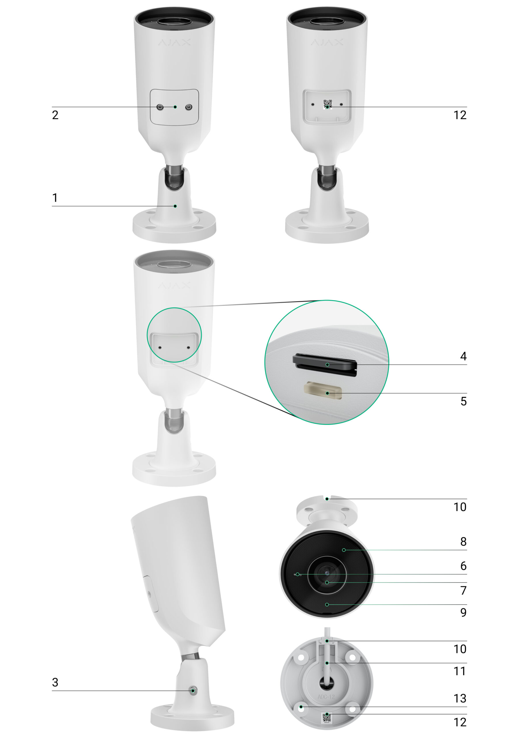
Prismatic lens (covers the IR LED and diffuses the light)
IR illumination (for recording in the dark and in low light)
Cable channel for the connector output from the camera
Cable connector
QR code with device ID (for connecting the BulletCam to the Ajax system)
Mounting holes for attaching the camera to a surface
How It Works
BulletCam is an IP camera that uses artificial intelligence (AI) for object recognition. Its algorithms can identify moving objects and distinguish between people, animals, and vehicles.
The device is equipped with smart IR illumination, which ensures high-quality images even in low-light conditions. The camera automatically adjusts the lighting intensity in real time, preventing overexposure and allowing for a clear view of both near and distant objects.
IP65 protection rating—suitable for outdoor installation.
A durable metal housing protects against tampering.
microSD card: 32 GB to 256 GB (V30 or faster; not included).
Can also operate without a memory card when used with an NVR.
Using the video storage calculator, you can estimate the required storage capacity and recording time based on your video stream settings.
BulletCam features:
Real-time video viewing with zoom.
Access to archived video by timeline or calendar (via microSD or NVR).
Configuration of motion zones and sensitivity adjustment.
Video wall (combines images from all cameras).
Quick access to automation device control from the video player menu.
Video scenarios: a short video clip sent to the Ajax app when a security detector is triggered.
Downloading archive clips to a smartphone or computer (via microSD or NVR).
Videos with firmware version 2.309 or later are signed with an Ajax digital signature (the Ajax media player can be used for verification).
ONVIF integration
Supported by BulletCam firmware version 2.356 or later.
Compatible with VMS (Milestone, Genetec, Axxon, Digifort).
Setup can be performed by an administrator or a PRO user with the following permissions:
Ajax Security System (v. 3.25+),
Ajax PRO: Tool for Engineers (v. 2.25+),
Ajax PRO Desktop (v. 4.20+),
Ajax Desktop (v. 4.21+).
Video Scenarios In the Ajax system, IP cameras can be used for alarm verification. Cameras can respond to alarms from a single detector, multiple detectors, or all detectors.
You can configure the siren to activate when motion is detected or an object is recognized by AI.
Video Wall Available on the Video Wall tab after at least one camera has been added.
In the Ajax mobile apps, you can:
Switch between cameras;
Search for a camera by name;
Control a PTZ camera.
In Ajax PRO Desktop, you can:
Switch between cameras;
Search for a camera by name;
Organize cameras by room, NVR, or group;
Control a PTZ camera;
Save custom layouts;
Change the camera display order;
Create slideshow templates.
The system allowsyou to hide part of the frame. For example, if a safe is visible, you can set up a zone so that activity around it is recorded without revealing its contents. Motion and objects will not be detected in these zones.
To configure this in the Ajax app:
Open the Devices tab.
Select a camera (or NVR → Cameras).
Go to Settings (by tapping the gear icon twice).
Select the Privacy Zones menu.
Open Configure Privacy Zones and mark the desired area.
Tap the icon. Return to the camera settings.
The user can create up to four privacy zones.
Choosing a Location
When choosing the best location to install the BulletCam, consider the camera’s field of view and any potential obstacles that could block the view.
How to install an Ajax camera for better AI recognition
When designing a security system, follow the installation recommendations. Security systems may only be designed and installed by professionals. A list of recommended partners is available here.
The camera must not be installed:
indoors or outdoors where the temperature and humidity do not meet the specified operating parameters;
in locations where objects or structures obstruct the camera’s field of view;
in direct bright light or facing bright objects (such as a white wall), as this reduces image quality. A bright surface reflects IR lighting and can blind the camera in the dark.
Installation
Connect the Ethernet cable to the camera. If the camera is powered via PoE, an external power supply is not required; otherwise, connect both the external power supply and the Ethernet cable.
Turn on the camera’s power supply. The LED indicator on the cable connector will light up green.
Connect the camera to the system, and then disconnect the Ethernet and power cables from the camera.
Using the included hex key (Ø 2 mm), unscrew the screws securing the protective cover. Insert a microSD card (not included) into the appropriate slot. Replace the protective cover and tighten the screws.
After connecting the BulletCam to the system, format the memory card in the camera settings.
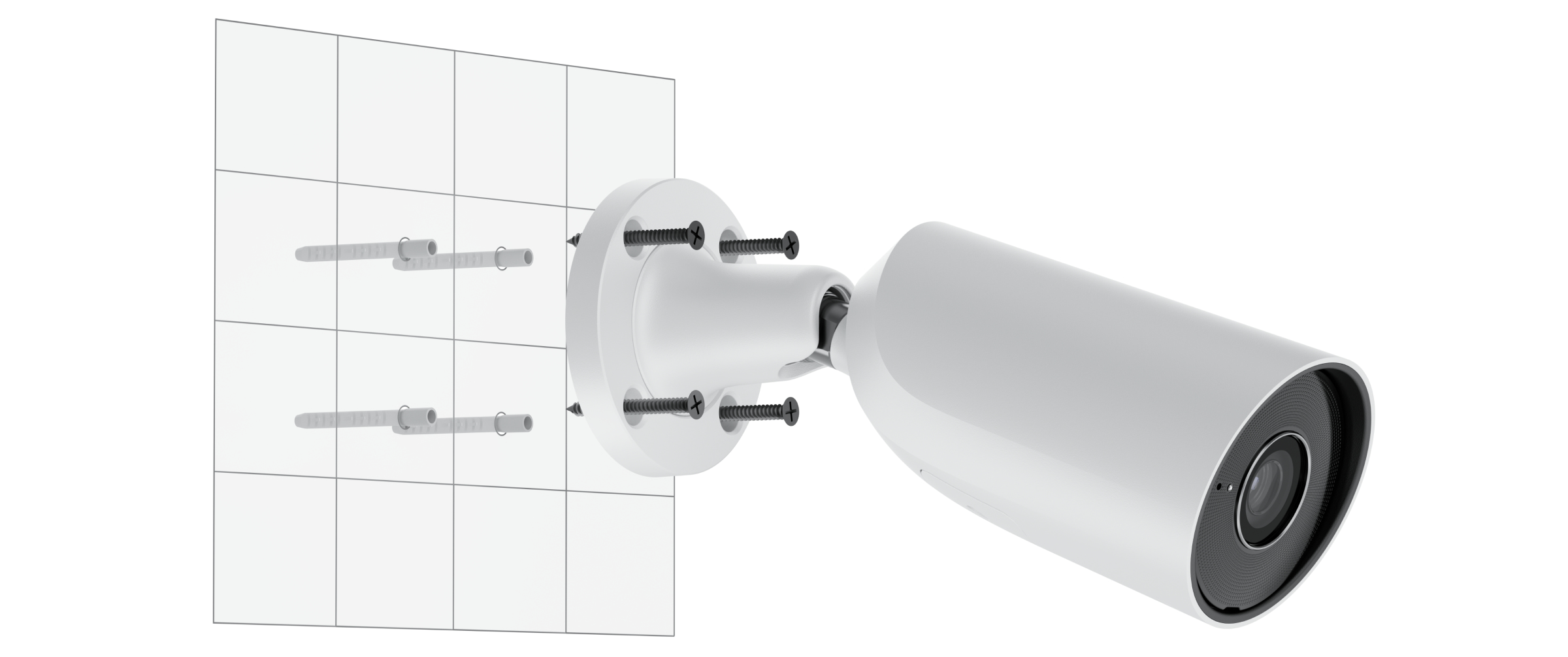
Using the mounting template, mark the drill holes on the surface where you plan to mount the camera. Secure the template in the selected location with adhesive tape and drill four holes as indicated on the template.
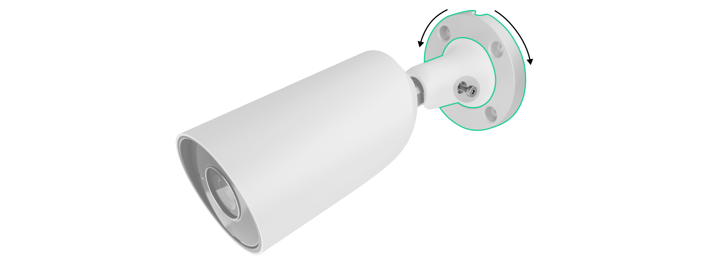
Unscrew the screw on the swivel mounting bracket using the included hex key (Ø 2 mm) and rotate the bracket if you need to adjust the position of the cable channel. Screw the screw back in.
Route the cable through the cable channel and secure the swivel mounting bracket to the surface using the screws included in the kit.
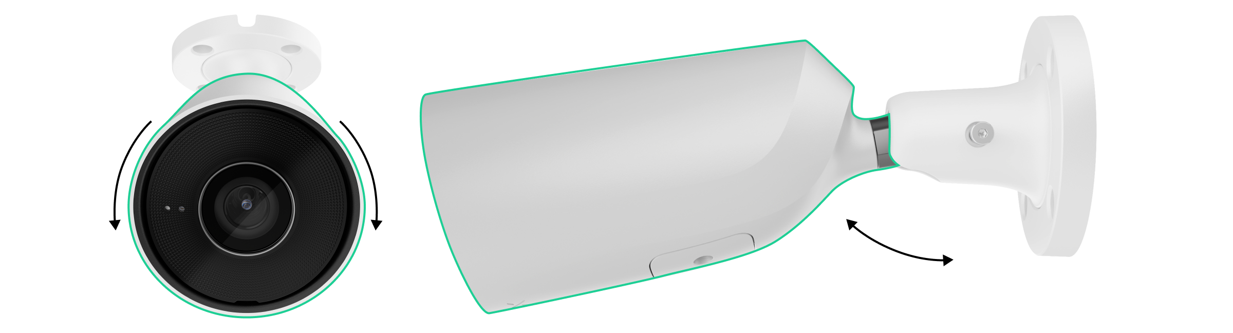
Unscrew the screw on the swivel mounting bracket to adjust the camera's tilt and rotation.
Make sure the camera lens is pointed toward the area to be monitored. Secure it by tightening the screw on the swivel mounting bracket.
Connect the Ethernet and power cables to the camera. Install a waterproof connector if the camera is used indoors where humidity levels exceed the operating specifications, or outdoors.
Recommended power supply specifications: 12 V⎓ ± 20% with a current of at least 1 A.
Turn on the camera’s power supply. The LED indicator on the cable connector will light up green.
Connecting to the System
Before connecting the device:
Install the Ajax app.
Sign in to your account or create a new one.
Select a room or create a new one.
Add at least one virtual room.
Make sure the room is disarmed.
Only a PRO user or a room administrator with system configuration rights can add a device to a room.
Account Types and Their Permissions How to Add a BulletCam
Restore to Factory Settings
To reset the camera to its factory settings:
Turn off the camera by disconnecting the external power source or the Ethernet cable (if power is supplied via PoE).
Press and hold the reset button.
Connect the camera to a power source while holding down the reset button, and wait until the LED indicator on the button lights up purple. This will take about 50 seconds.
The LED indicator lights up blue for 20 seconds after the camera is turned on while the reset button is held down. It then turns off for 30 seconds and lights up purple. This means the camera has been restored to its factory settings.
Release the button.
Icons
In the Ajax app, icons indicate the device's status. To view them:
Select a room in the Ajax app.
Open the Devices tab.
Find BulletCam in the list.
Icon — Meaning
Additional services have been activated in accordance with the subscription.
The device is operating in Night Mode.
No microSD card is installed.
The microSD card is installed.
A microSD card error has been detected—formatting is recommended.
The microSD card is being formatted.
A new firmware version is available.
Firmware update in progress: downloading/installing.
Firmware update error.
The device has lost its connection to the Ajax Cloud server.
Connection enabled via ONVIF.
You do not have access to the video.
Statuses
The status section provides information about the device and its operating parameters. You can view this information in the Ajax apps:
Select a room.
Open the Devices tab.
Select BulletCam from the list. If BulletCam is connected to a video recorder, select NVR and then Cameras.
(The following is a detailed list of parameters: Errors, Firmware Update, Connection, Connection to NVR, Memory Location, Memory Card, Resolution, Frame Rate, Bit Rate, Video Codec, Motion Detection, Object Detection, Uptime, ONVIF Integration, Viewing Permissions, Firmware, ID, etc.)
Settings
To change the camera settings in the Ajax app:
Open the Devices tab.
Select BulletCam (or NVR → Cameras).
Go to Settings.
Set the necessary parameters.
Tap Back to save.
(The following is a detailed list of settings: Name, Room, Night Mode, Recording Modes, Detector Alerts, Video Stream Settings, Image Quality Settings, Audio, Privacy Zones, Firmware Updates, Connection, Memory Card, Monitoring, Service, etc.)
Indications
A green LED indicator is located on the cable connector.
Event
Indications
Note
The camera is powered.
The green light is on.
Errors
If a BulletCam detects an error, an error counter appears on the device icon in the Ajax app. All errors are visible in the camera's Status section. Fields containing errors are highlighted in red.
Errors are displayed if:
The camera loses its connection to the server;
There is an error with the storage device (press the camera's reset button or format the storage device in the settings);
The storage device needs to be formatted.
Maintenance
Check the camera's operation regularly. If you notice a decline in image quality, blurriness, or darkening, inspect the camera. Clean the housing to remove dust, cobwebs, and other debris. Use soft, dry wipes designed for cleaning electronics.
Do not use substances containing alcohol, acetone, gasoline, or other harsh solvents. Clean the lens carefully—scratches can result in poor image quality and damage to the camera.
Technical Specifications
BulletCam (5 MP/2.8 mm)
BulletCam (5 MP/4 mm)
BulletCam (8 MP/2.8 mm)
BulletCam (8 MP/4 mm)
Compliance with Standards
Warranty
The product warranty for Ajax Systems Manufacturing, Ltd. is valid for 2 years from the date of purchase.
If you encounter any issues with the device's operation, please contact Ajax technical support first. In most cases, issues can be resolved remotely.
Prismatic lens (covers the IR LED and diffuses the light)
IR illumination (for recording in the dark and in low light)
Cable channel for the connector output from the camera
Cable connector
QR code with device ID (for connecting the BulletCam to the Ajax system)
Mounting holes for attaching the camera to a surface
How It Works
BulletCam is an IP camera that uses artificial intelligence (AI) for object recognition. Its algorithms can identify moving objects and distinguish between people, animals, and vehicles.
The device is equipped with smart IR illumination, which ensures high-quality images even in low-light conditions. The camera automatically adjusts the lighting intensity in real time, preventing overexposure and allowing for clear visibility of both near and distant objects.
IP65 protection rating—suitable for outdoor installation.
A durable metal housing protects against tampering.
microSD card: 32 GB to 256 GB (V30 or faster, not included).
Can also operate without a memory card when used with an NVR.
Using the video storage calculator, you can estimate the required storage capacity and recording time based on video stream settings.
BulletCam features:
Real-time video viewing with zoom.
Access to archived video by chronology or calendar (via microSD or NVR).
Configuration of motion zones and sensitivity adjustment.
Video wall (combines images from all cameras).
Quick access to automation device control from the video player menu.
Video scenarios: a short video clip sent to the Ajax app when a security detector is triggered.
Downloading archive clips to a smartphone or computer (via microSD or NVR).
Videos with firmware version 2.309 or later are signed with an Ajax digital signature (the Ajax media player can be used for verification).
ONVIF integration
Supported by BulletCam firmware version 2.356 and later.
Compatible with VMS (Milestone, Genetec, Axxon, Digifort).
Setup can be performed by an administrator or a PRO user with the following permissions in the following applications:
Ajax Security System (v. 3.25+),
Ajax PRO: Tool for Engineers (v. 2.25+),
Ajax PRO Desktop (v. 4.20+),
Ajax Desktop (v. 4.21+).
Video Scenarios In the Ajax system, IP cameras can be used for alarm verification. Cameras can respond to alarms from a single detector, multiple detectors, or all detectors.
You can configure the siren to activate when motion is detected or an object is recognized by AI.
Video Wall Available on the Video Wall tab after at least one camera has been added.
In the Ajax mobile apps, you can:
Switch between cameras;
Search for a camera by name;
Control a PTZ camera.
In Ajax PRO Desktop, you can:
Switch between cameras;
Search for a camera by name;
Organize cameras by room, NVR, or group;
Control a PTZ camera;
Save custom layouts;
Change the camera display order;
Create slideshow templates.
The system allowsyou to hide part of the frame. For example, if a safe is visible, you can set up a zone so that activity around it is recorded without revealing its contents. Motion and objects will not be detected in these zones.
To configure this in the Ajax app:
Open the Devices tab.
Select a camera (or NVR → Cameras).
Go to Settings (by tapping the gear icon twice).
Select the Privacy Zones menu.
Open Configure Privacy Zones and mark the desired area.
Tap the icon. Return to the camera settings.
The user can create up to four privacy zones.
Choosing a Location
When choosing the best location to install the BulletCam, consider the camera’s field of view and any potential obstacles that could block the view.
How to install an Ajax camera for better AI recognition
When designing a security system, follow the installation recommendations. Security systems may only be designed and installed by professionals. A list of recommended partners is available here.
The camera must not be installed:
indoors or outdoors where the temperature and humidity do not meet the specified operating parameters;
in locations where objects or structures obstruct the camera’s field of view;
in direct bright light or facing bright objects (such as a white wall), as this reduces image quality. A bright surface reflects IR illumination and dazzles the camera in the dark.
Installation
Connect the Ethernet cable to the camera. If the camera is powered via PoE, an external power supply is not required; otherwise, connect both the external power supply and the Ethernet cable.
Turn on the camera’s power supply. The LED indicator on the cable connector will light up green.
Connect the camera to the system, and then disconnect the Ethernet and power cables from the camera.
Using the included hex wrench (Ø 2 mm), unscrew the screws securing the protective cover. Insert a microSD card (not included) into the appropriate slot. Replace the protective cover and tighten the screws.
After connecting the BulletCam to the system, format the memory card in the camera settings.
Using the mounting template, mark the drill holes on the surface where you plan to mount the camera. Secure the template in the selected location with adhesive tape and drill four holes as indicated on the template.
Unscrew the screw on the swivel mounting bracket using the included hex key (Ø 2 mm) and rotate the bracket if you need to adjust the position of the cable channel. Screw the screw back in.
Route the cable through the cable channel and secure the swivel mounting bracket to the surface using the screws provided.
Unscrew the screw on the swivel mounting bracket to adjust the camera's tilt and rotation.
Make sure the camera lens is pointed toward the area to be monitored. Secure it by tightening the screw on the swivel mounting bracket.
Connect the Ethernet and power cables to the camera. Install a waterproof connector if the camera is used indoors where humidity levels exceed the operating parameters or outdoors.
Recommended power supply specifications: 12 V⎓ ± 20% with a current of at least 1 A.
Turn on the camera’s power supply. The LED indicator on the cable connector will light up green.
Connecting to the System
Before connecting the device:
Install the Ajax app.
Sign in to your account or create a new one.
Select a room or create a new one.
Add at least one virtual room.
Make sure the room is disarmed.
Only a PRO user or a room administrator with system configuration rights can add a device to a room.
Account Types and Their Permissions How to Add a BulletCam
Restore to Factory Settings
To reset the camera to its factory settings:
Turn off the camera by disconnecting the external power source or the Ethernet cable (if power is supplied via PoE).
Press and hold the reset button.
Connect the camera to a power source while holding down the reset button, and wait until the LED indicator on the button turns purple. This will take about 50 seconds.
The LED indicator lights up blue for 20 seconds after the camera is turned on while the reset button is held down. It then turns off for 30 seconds and lights up purple. This means the camera has been restored to its factory settings.
Release the button.
Icons
In the Ajax app, icons indicate the device's status. To view them:
Select a room in the Ajax app.
Open the Devices tab.
Find BulletCam in the list.
Icon — Meaning
Additional services have been activated in accordance with the subscription.
The device is operating in Night Mode.
No microSD card is installed.
The microSD card is installed.
A microSD card error has been detected—formatting is recommended.
The microSD card is being formatted.
A new firmware version is available.
Firmware update in progress: downloading/installing.
Firmware update error.
The device has lost its connection to the Ajax Cloud server.
Connection enabled via ONVIF.
You do not have access to the video.
Statuses
The status section provides information about the device and its operating parameters. You can view this information in the Ajax apps:
Select a room.
Open the Devices tab.
Select BulletCam from the list. If BulletCam is connected to a video recorder, select NVR and then Cameras.
(The following is a detailed list of parameters: Errors, Firmware Update, Connection, Connection to NVR, Memory Location, Memory Card, Resolution, Frame Rate, Bit Rate, Video Codec, Motion Detection, Object Detection, Uptime, ONVIF Integration, Viewing Permissions, Firmware, ID, etc.)
Settings
To change the camera settings in the Ajax app:
Open the Devices tab.
Select BulletCam (or NVR → Cameras).
Go to Settings.
Set the necessary parameters.
Tap Back to save.
(The following is a detailed list of settings: Name, Room, Night Mode, Recording Modes, Detector Alerts, Video Stream Settings, Image Quality Settings, Audio, Privacy Zones, Firmware Updates, Connection, Memory Card, Monitoring, Service, etc.)
Indications
A green LED indicator is located on the cable connector.
Event
Indications
Note
The camera is powered.
The green light is on.
Errors
If a BulletCam detects an error, an error counter appears on the device icon in the Ajax app. All errors are visible in the camera's Status section. Fields with errors are highlighted in red.
Errors are displayed if:
The camera loses its connection to the server;
There is an error with the storage device (press the camera's reset button or format the storage device in the settings);
The storage device needs to be formatted.
Maintenance
Check the camera's operation regularly. If you notice a decline in image quality, blurriness, or darkening, inspect the camera. Clean the housing of dust, cobwebs, and other debris. Use soft, dry wipes designed for cleaning electronics.
Do not use substances containing alcohol, acetone, gasoline, or other harsh solvents. Clean the lens carefully—scratches can result in poor image quality and damage to the camera.
Technical Specifications
BulletCam (5 MP/2.8 mm)
BulletCam (5 MP/4 mm)
BulletCam (8 MP/2.8 mm)
BulletCam (8 MP/4 mm)
Compliance with Standards
Warranty
The product warranty for Ajax Systems Manufacturing, Ltd. is valid for 2 years from the date of purchase.
If you encounter any issues with the device's operation, please contact Ajax technical support first. In most cases, issues can be resolved remotely.
Available for pickup at
Out of stock at
Added to compare
Reached count_product-product limit
Added to compare
Reached count_product-product limit
{"id":49985983709519,"title":"Default Title","option1":"Default Title","option2":null,"option3":null,"sku":"367311721","requires_shipping":true,"taxable":true,"featured_image":null,"available":true,"name":"AJAX TURRETCAM 5Mp 2.8MM white 12V.For outdoor and indoor use. Powered IP security camera with 110° viewing angle","public_title":null,"options":["Default Title"],"price":16230,"weight":0,"compare_at_price":20700,"inventory_management":"shopify","barcode":null,"requires_selling_plan":false,"selling_plan_allocations":[],"quantity_rule":{"min":1,"max":null,"increment":1}}
AJAX TURRETCAM 5Mp 2.8MM white 12V.For outdoor and indoor use. Powered IP security camera with 110° viewing angle
SKU: 367311721
€162,30€207,00
Unit price
5 MP/2.8 mm Resolution up to 2880 × 1620 px Frame rate up to 25 FPS Viewing angle 100° to 110°
Fast and encrypted peer-to-peer video protocol developed by Ajax Systems.
Storage NVR
Hard disk drive up to 16 TB (SATA connection, 3.5" size). Memory storage device not included.
microSD
Up to 256 GB. Memory card must be Class 30 or higher. Storage device not included.
Video codecs H.265 H.264
Dynamic Ranges True WDR
Communication channel Ethernet up to 100 Mbps
Available for pickup at
Out of stock at
Added to compare
Reached count_product-product limit
Added to compare
Reached count_product-product limit
{"id":53505646494031,"title":"Default Title","option1":"Default Title","option2":null,"option3":null,"sku":"367311712","requires_shipping":true,"taxable":true,"featured_image":null,"available":true,"name":"AJAX DomeCam Mini (5 Mp\/2.8 mm) black- IP network camera (black) with 110° ~ 110° viewing angle.","public_title":null,"options":["Default Title"],"price":15999,"weight":0,"compare_at_price":17000,"inventory_management":"shopify","barcode":null,"requires_selling_plan":false,"selling_plan_allocations":[],"quantity_rule":{"min":1,"max":null,"increment":1}}
AJAX DomeCam Mini (5 Mp/2.8 mm) black- IP network camera (black) with 110° ~ 110° viewing angle.
SKU: 367311712
€159,99€170,00
Unit price
The AJAX DomeCam Mini (5 Mp/2.8 mm) is an IP network camera (product colour: black) with a resolution of up to 2880 × 1620 px and a built-in 2.8 mm fixed lens with a viewing angle of 100° ~ 110°. This IP camera features true WDR image processing, intelligent infrared (IR) backlighting up to 15 metres and object recognition. Users can view archived and live video in the Ajax Security System application. The AJAX DomeCam Mini can operate without an Ajax NVR by recording the archive to an SD card (sold separately).
Ajax vhfBridge, Integration module, AJAX VHF radio communicator (8 outputs), compatible with Hub 2, Hub Plus, Hub 2 Plus, white
SKU: 367308959
€124,24€158,46
Unit price
vhfBridge Jeweller User manual
vhfBridge Jeweller is a module for connecting Ajax security systems to third-party VHF transmitters. It provides 8 transistor outputs for connection to third-party VHF transmitters.
The device is powered from 100-240 V~ mains and can be operated from a 12 V⎓ backup battery.
vhfBridge Jeweller operates as part of the Ajax security system and connects to the hub via the Jeweller secure radio communication protocol. The hub communication range is up to 1,800 meters without obstacles. Supplied in two configurations: with a casing and without it.
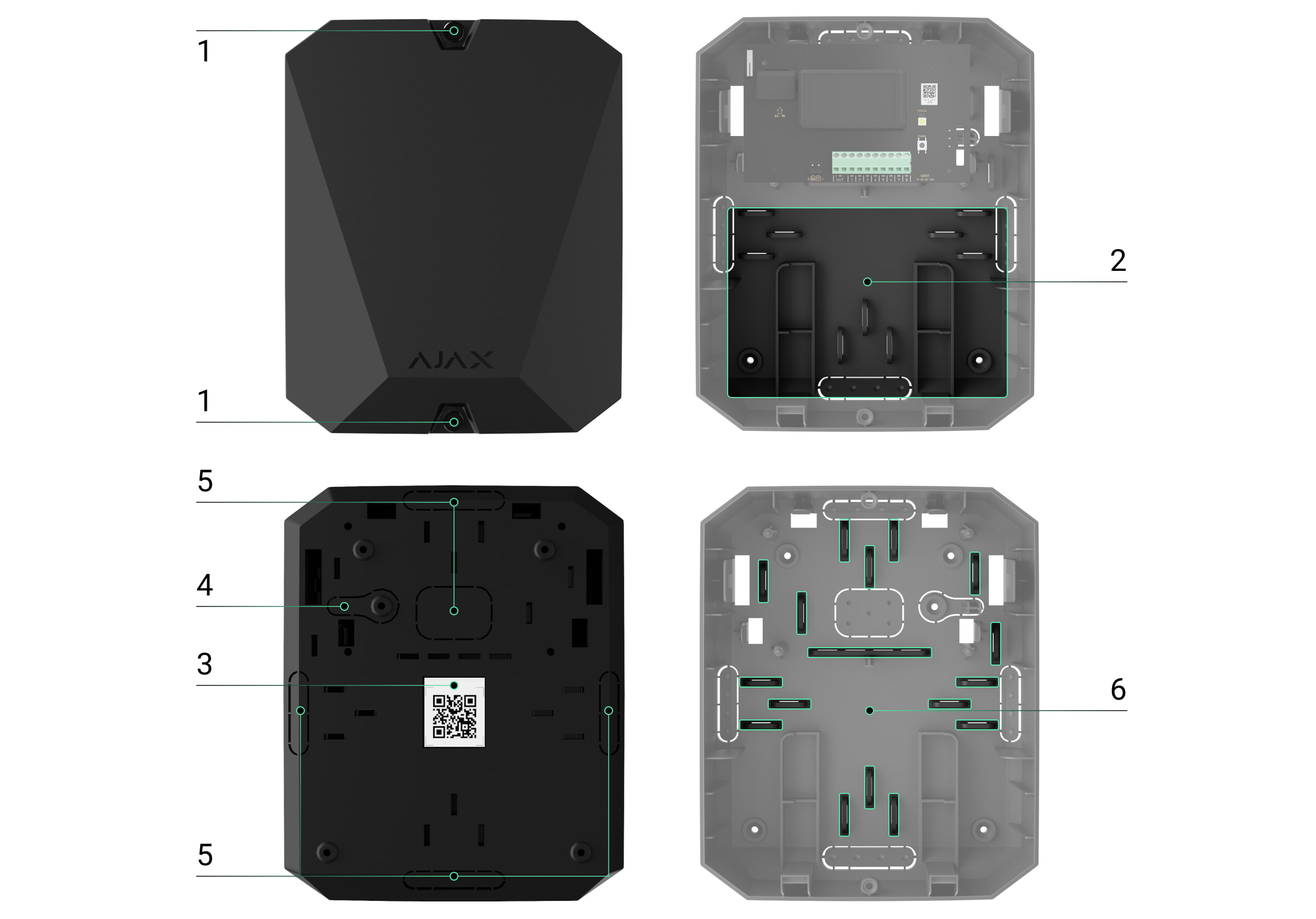
Screws securing the casing lid. Unscrew with a bundled hexagon key (Ø 4 mm).
Space for a 12 V⎓ backup battery.
Battery not included with vhfBridge Jeweller set.
QR code with the device ID. It is used to pair the device with the Ajax security system.
Perforated part of the casing. Necessary for tamper triggering in case of any attempt to detach the device from the surface.
Perforated parts of the casing for cable output.
The presence of the casing depends on the vhfBridge Jeweller package. The device is supplied in two configurations: with a casing and without it.
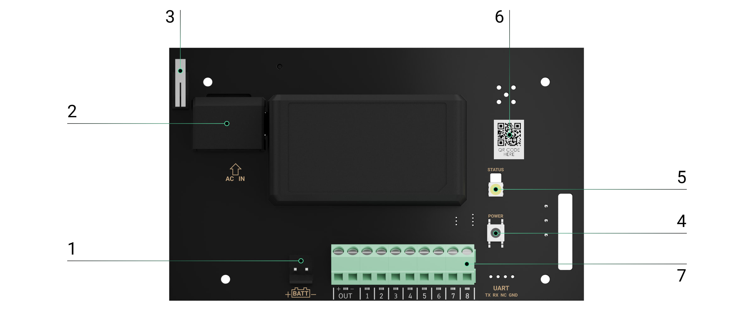
vhfBridge Jeweller board elements
Terminals for connecting a 12 V⎓ backup battery.
100-240 V~ power supply input.
Tamper button. Signals if vhfBridge Jewellercasing lid is removed.
Power button.
LED indicator.
QR code with the device ID. It is used to pair the device with the Ajax security system.
Terminals for connecting a VHF transmitter.
vhfBridge Jeweller terminals
BATT - input for the 12 V⎓ backup power connection.
OUT - power output for the 12 V⎓ VHF transmitter (maximum output current is 2 A).
OUT 1...8 - vhfBridge Jeweller outputs for connecting a VHF transmitter.
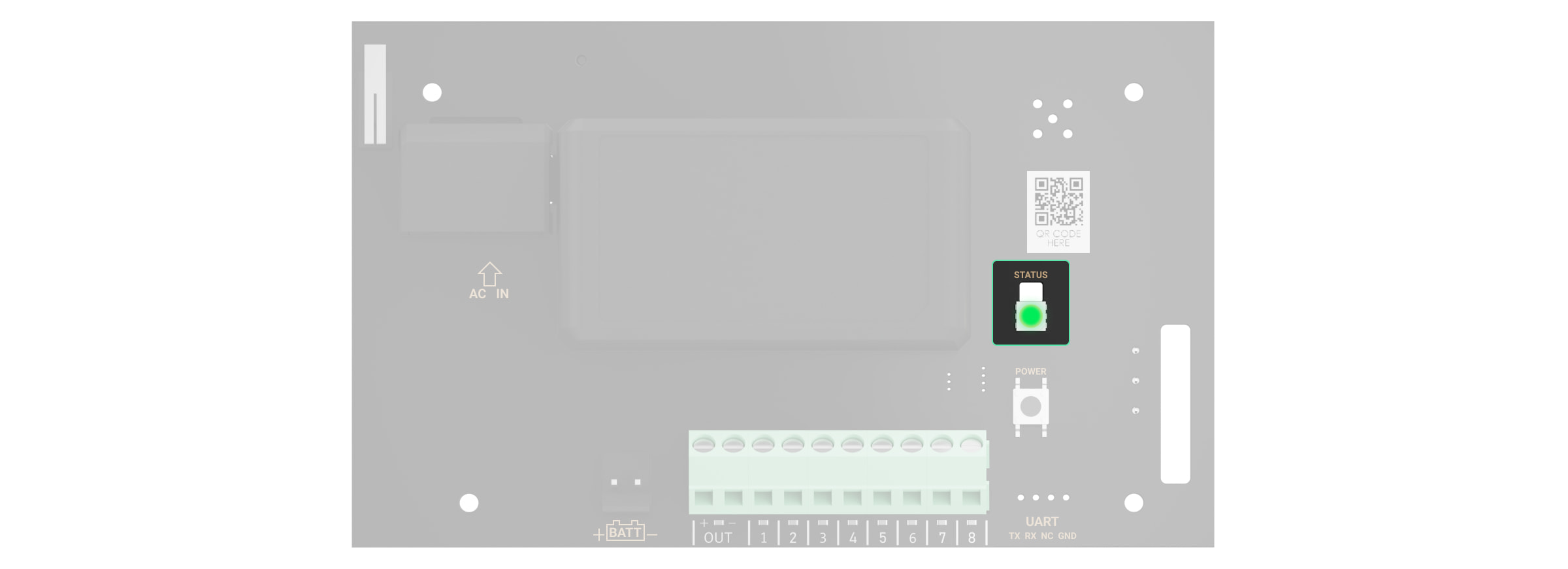
LED indication
vhfBridge Jeweller LED indicator may light up white, red, or green, depending on the status of the device.
Please note that the LED indicator is not visible when the casing lid is closed. The LED indicator is used at the stage of vhfBridge Jeweller connecting and configuring. Later on, the state of the device can be monitored in the Ajax app.
LED indication
Event
Note
Lights up white.
Connection with the hub is established, external power supply is connected.
Lights up red.
There is no connection with the hub, external power supply is connected.
For example, the hub is turned off or vhfBridge Jeweller is outside the coverage area of the hub's wireless network.
Goes out for 0.5 seconds, then lights up green and turns off.
Enabling vhfBridge Jeweller.
Goes out for 0.5 seconds, then lights up green and fades out over 3 seconds.
Disabling vhfBridge Jeweller.
Blinks red once per second.
vhfBridge Jeweller is not assigned to a hub.
Lights up for a second once every 10 seconds.
No external power supply is connected to vhfBridge Jeweller.
The colour of the indication depends on the status of connection with the hub:
lights up white if there is connection with the hub;
lights up red if there is no connection with the hub.
During an alarm, gradually lights up and goes out once every 10 seconds.
No external power supply and discharged external battery of vhfBridge Jeweller.
The colour of the indication depends on the status of connection with the hub:
lights up white if there is connection with the hub;
lights up red if there is no connection with the hub.
LED indication of output status
LED indication
Output status in case of alarm
High potential output (positive trip).
Lights up green.
Low potential output (negative trip).
Goes out.
Operating principle
vhfBridge Jeweller is designed to connect third-party VHF transmitters to create an additional channel for transmitting events to the CMS.
The communication channel with the CMS created using vhfBridge Jeweller can be used as the only or as a backup channel for communicating with the CMS (recommended more reliable option). This means that the hub can simultaneously transmit all events and alarms to the monitoring station of the security company not only through SIA (DC-09), ADEMCO 685, SurGard (Contact ID), and other proprietary protocols but also using vhfBridge Jeweller.
The transponder receives information about alarms and events from the hub via the Jeweller radio channel. Then, vhfBridge Jeweller transmits it to a third-party VHF transmitter via wires. The VHF transmitter, in turn, transmits all events and alarms to the CMS via a radio channel.
Events can be transmitted to the CMS via the Internet and vhfBridge Jeweller in parallel. Transmission via the Internet works as the main channel because of greater reliability and informativity. The transmitted events may contain the zone number of the triggered detector, group number, user number, and other data.
vhfBridge Jeweller works as a backup communication channel duplicating all events transmitted via the Internet. The delivery speed of events and alarms in both cases does not exceed 1 second.
An example of the algorithm of actions in case of an alarm from a MotionProtect motion detector:
MotionProtect has detected an alarm.
MotionProtect transmits the alarm to the hub via the Jeweller radio protocol.
The hub receives the MotionProtect alarm and transmits it to vhfBridge Jeweller via the Jeweller radio protocol.
The vhfBridge Jeweller receives the alarm from the hub and transmits it to the VHF transmitter over a wired connection.
The VHF transmitter receives the alarm and transmits it to the radio receiver on the CMS side via the radio channel.
The radio receiver receives the alarm and transmits it to the CMS software.
The CMS receives and processes the alarm.
Output types
vhfBridge Jeweller has 8 potential outputs for connection to a VHF transmitter. There are two types of outputs:
High potential output (positive trip).
Low potential output (negative trip).
The high-potential output does not supply voltage in the normal state. As soon as an alarm or event occurs, the output supplies a voltage of 12-14 V⎓. The low-potential output works the other way around. In the normal state, the voltage is maintained at 12-14 V⎓, and when an alarm or event occurs, it drops to 0 V.
The vhfBridge Jeweller output type and alarm pulse duration are configurable in Ajax apps.
VHF transmitter power supply
The vhfBridge Jeweller can supply a third-party VHF transmitter with 12 V⎓ power (maximum output current is 2 A).
If the VHF transmitter has a current consumption of more than 2 A, it can be powered by the vhfBridge Jeweller battery. In this case, disable battery charge tracking in the vhfBridge Jeweller settings so that the system users do not receive notifications about the vhfBridge Jeweller battery charging too long.
Sending events to the Central Monitoring Station (CMS)
The Ajax security system can transmit alarms to thePRO Desktopmonitoring app as well as the Central Monitoring Station (CMS) usingSurGard (Contact ID),SIA DC-09 (ADM-CID),ADEMCO685, and other proprietary protocols. The list of supported protocols isavailable here.
When an alarm is received, the monitoring station operator of the security company knows what happened and where the rapid response unit has to be sent. All Ajax devices are addressable, so events, the device type, its assigned name and room can be transmitted to the PRO Desktop and the CMS. The list of transmitted parameters may differ depending on the type of the CMS and the selected communication protocol.
You can find vhfBridge Jeweller ID and zone number in the Statesin Ajax apps. The device number corresponds to the loop (zone) number.
Adding to the system
vhfBridge Jeweller doesn't work with Hub, ocBridge Plus, uartBridge and third-party security central units.The device can only be added and configured through the Ajax PRO app by a user with administrator rights.
Open the Ajax app. If your account has access to multiple hubs, select the one to which you want to add vhfBridge Jeweller.
Go to the Devices menu and click Add Device.
Name the transponder, scan or enter the QR code manually (located on the device casing and packaging), and select a room and a group (if the group mode is activated).
Click Add- the countdown will begin.
Switch on vhfBridge Jeweller by holding the power button for 3 seconds. Keep in mind that the hub connection request is only sent when the integration module is turning on.
Please note that to find and pair the device, the transponder should be located within the hub's radio communication range (on the same secured premises).
If the connection has failed, disconnect vhfBridge Jeweller for 5 seconds and try again. If the transponder has already been assigned to another hub, turn off vhfBridge Jeweller and then follow the standard addition procedure.
The connected transponder will appear in the list of hub devices in the app. Device status updates depend on Jeweller settings. The default status update period in the app is 36 seconds.
Malfunction counter
When a vhfBridge Jeweller malfunction is detected (e.g., no external power), the Ajax app will display a red icon with a number in the upper left corner of the device icon. This number indicates the number of malfunctions.
All malfunctions can be seen in the transponder states. Fields with malfunctions will be highlighted in red.
Icons
Icons display some of the vhfBridge Jeweller states. You can check them in the Ajax app in the Devices tab.
Icon
Meaning
Jeweller Signal Strength. Displays the signal strength between the hub and vhfBridge Jeweller.
Recommended value is 2-3 bars.
The charge level of the battery connected to vhfBridge Jeweller.
The presence of the 100-240 V~ external power supply:
Connected - the external power is connected.
Disconnected - the external power is disconnected.
Name of ReX range extender
Radio signal range extender connection status:
Online - the device is connected.
Offline - the device is not connected.
Please note that the field is displayed if vhfBridge Jeweller is operated via a radio signal range extender.
Permanent Deactivation
Shows the status of the device permanent deactivation function:
No - the device operates in normal mode and transmits all events.
Lid only - the hub admin disabled notifications about tamper alarms.
Entirely - the device is completely excluded from the system operation by the hub admin. The device does not follow system commands and does not report alarms or other events.
Firmware
vhfBridge Jeweller firmware version.
Device ID
vhfBridge Jeweller ID/serial number. Also located on the device box, its board, and the casing.
Device No.
Device loop (zone) number.
vhfBridge Jeweller settings
Settings can be changed in the Ajax app:
Go to the Devices tab.
Select vhfBridge Jeweller from the list.
Go to Settings by clicking the icon in the upper right corner.
Set the parameters.
ClickBackto save the new settings.
Please note that after editing the settings, you should click the Back button to save them.
Configuration
Meaning
Name
vhfBridge Jeweller name. Displayed in the text of SMS and notifications in the event feed.
To change the device name, click on the pencil icon.
The name can contain up to 12 Cyrillic characters or up to 24 Latin characters.
Room
Selecting the virtual room to which vhfBridge Jeweller is assigned.
The room name is displayed in the text of SMS and notifications in the event feed.
Track battery charge time
Set up the battery charge duration.
When this option is enabled, the system will send a malfunction notification if the battery connected to vhfBridge Jeweller has been charging more than 40 hours.
Disable tracking if the VHF transmitter is powered directly from the battery and not from the vhfBridge Jeweller power terminals.
Pulse Duration, sec
Pulse time on an event (from 1 to 255 seconds). Set in increment of 1 second.
The default value is 5 seconds.
Jeweller Signal Strength Test
Switches vhfBridge Jeweller to the Jeweller signal strength test mode.
The test allows you to check the signal strength between the hub and vhfBridge Jeweller and determine the optimal installation location.
Allows the user to disable the device without removing it from the system.
Three options are available:
No - the device operates in normal mode and transmits all events.
Entirely - the device will not execute system commands or participate in automation scenarios, and the system will ignore device alarms and other notifications.
Lid only - the system will ignore notifications about the triggering of the device tamper only.
Opens vhfBridge Jeweller User Guide in the Ajax app.
Unpair Device
Unpairs vhfBridge Jeweller, disconnects it from the hub, and deletes its settings.
vhfBridge Jeweller output configuration
By default, vhfBridge Jeweller outputs are configured as follows:
1st output - intrusion
2nd output - panic button
3rd output - malfunction
4th output - tamper
5th output - loss of vhfBridge Jeweller power supply
6th output - power loss of the hub
7th output - hub battery discharged
8th output - loss of communication between the hub and vhfBridge Jeweller
The settings of outputs can be changed in the Ajax app:
Go to the Devices tab.
Find vhfBridge Jeweller in the list of devices.
Go to the Outputs menu.
Find the output in the list and go to its Settings by clicking the gear icon .
Set the parameters.
Click Back to save the new settings.
Operating mode Selecting the output operating mode:
Pulse- vhfBridge Jeweller generates a pulse of a specified duration when activated.
Bistable- vhfBridge Jeweller changes the state of the contacts to the opposite (e.g., closed to open) when activated. In this mode, contacts will reset their state on disarming or system restore (ifRestoration after alarmis enabled for the same event type as the output).
This setting is available for users with administrator rights or in the PRO app. If the device is connected to hubs with firmware version OS Malevich 2.27 and later.
Configuration
Meaning
Type of Event
Selection of the event type to which vhfBridge Jeweller output reacts.
Check the complete list of event types and their icons below.
Connection type
Selection of the output type:
High potential output (positive trip).
Low potential output (negative trip).
Event types of vhfBridge Jeweller outputs
Icon
Type of event
Operating mode
Description
Not assigned
No
Output disabled.
Intrusion
Pulse
Alarm when motion, opening, and other detectors are triggered.
Fire
Pulse
Alarm when fire detectors are triggered.
Auxiliary alarm
Pulse
Alarm when pressing the auxiliary request alert button.
Confirmed hold-up device alarm according to PD 6662:2017.
Hub-transponder connection loss
Bistable
Loss of vhfBridge Jeweller connection with the hub / radio signal range extender via Jeweller channel.
The time before sending an event regarding the loss of communication between the hub and vhfBridge Jeweller to the CMS is calculated with the following formula:
With the minimum values of the "hub - detector" polling interval, an event regarding the loss of communication with the hub is sent to the CMS in 6 minutes.
Connecting VHF transmitter to vhfBridge Jeweller
List of recommended VHF transmitters
Hawk VHF Alarm Transmitter (FSK Electronics)
TX750C (RDC)
TR-41 (Puper)
vhfBridge Jeweller can be connected to any VHF transmitter with relay inputs. Connection via UART, RS-485, and other interfaces is not supported.
How to connect a VHF transmitter to vhfBridge Jeweller
When connecting the VHF transmitter, do not twist the wires together, but solder them. The ends of the VHF transmitter wires, which will be inserted into the vhfBridge Jeweller terminals should be tinned or crimped with a special sleeve.
Turn off the vhfBridge Jeweller power (if power was connected).
Turn off vhfBridge Jeweller.
Select vhfBridge Jeweller outputs to which you want to connect the VHF transmitter.
Pull the VHF transmitter wires into the vhfBridge Jeweller casingthrough the holes.
There are perforated sections on the casing that can be broken off so that the cable could be pulled through them.
Connect the VHF transmitter to the control outputs of vhfBridge Jeweller according to the wiring diagram in the User Guide supplied by the VHF transmitter manufacturer.
Fasten the cable securely to the vhfBridge Jeweller terminals using a straight screwdriver (slot PL 3.0).
Connect the power to the VHF transmitter.
If a VHF transmitter requires 12 V power to operate, it can be connected to the power terminals of the corresponding vhfBridge Jeweller zone. Do not connect the external power supply to the transmitter power terminals, as this may damage the device.
Connect power to vhfBridge Jeweller.
Turn on vhfBridge Jeweller.
vhfBridge Jeweller functionality testing
Integration module functionality tests do not start immediately but not later than over a single "hub - detector" polling interval (36 seconds with standard hub settings). You can change the polling period of devices in the Jeweller menu of the hub settings.
The placement of vhfBridge Jeweller determines its distance from the hub and the presence of obstacles between them that impede the passage of the radio signal: walls, inter-floor constructions, or large-sized objects located in the room.
Be sure to check the signal strength at the installation site. If the signal strength is low (a single bar), we cannot guarantee a stable operation of the security system. At the very least, relocate the device as repositioning even by 20 cm can significantly improve signal reception.
If poor or unstable signal strength is still reported after the relocation of the device, use the radio signal range extender.
When choosing the installation location, consider the distance between vhfBridge Jeweller and the VHF transmitter: the cable length should be sufficient for connection.
The minimum distance between vhfBridge Jeweller and the radio transmitter is 2 meters and the maximum distance is 7 meters. The minimum distance is required to avoid signal overlapping. The maximum distance allowed will help avoid signal attenuation in the cable.
Material and cross-section of the cable for connecting a VHF transmitter are determined by the manufacturer's requirements and the maximum current. All requirements can be found in the manual or from the customer service of the VHF transmitter manufacturer.
vhfBridge Jeweller installation
Prior to mounting vhfBridge Jeweller, ensure that you have selected the optimal location corresponding to these instructions.
The transponder casing should be mounted on a vertical surface. If installed on a horizontal surface, thetamperwill not work when somebody attempts to dismantle the transponder.
To install vhfBridge Jeweller:
Remove the vhfBridge Jeweller casing lid by unscrewing the bottom and top screws with the bundled hex wrench.
Remove the vhfBridge Jeweller board from the holders by pulling them to the sides.
Prepare cable openings in advance by carefully breaking out the perforated parts of the casing.
Fasten the casing to a vertical surface at the chosen installation location using the bundled screws. When attaching, use all the fixation points on the casing. One of them, in the perforated part of the mount above the tamper, is needed to trigger the tamper on the back of the board in case of an attempt to tear the casing off the surface.
Run the cables into the transponder casing through the previously made holes.
Install the vhfBridge Jeweller board into the casing on the racks.
Secure the cable with cable ties using special mounts inside the casing.
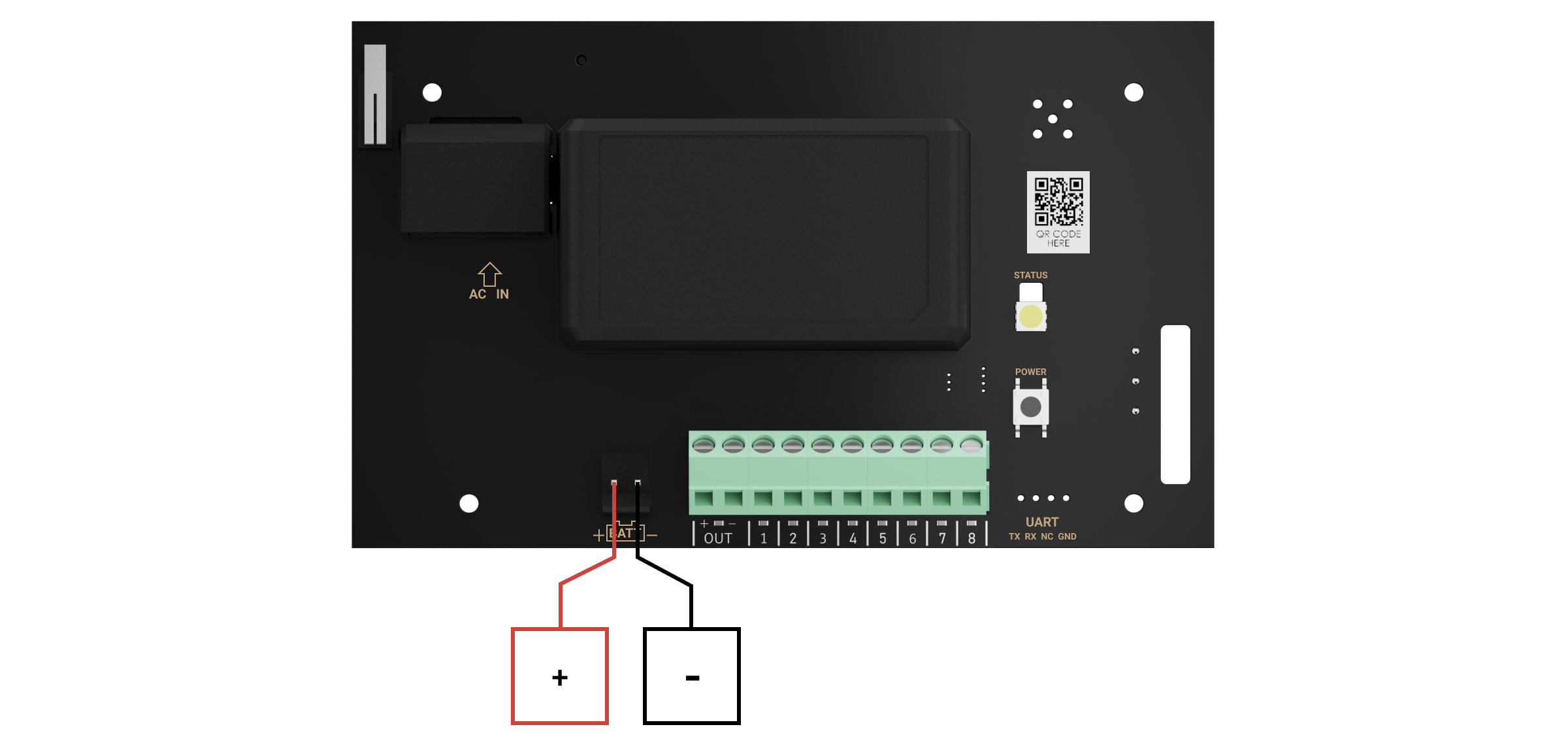
Install a 12 V⎓ backup battery on the special holders in the casing. Please note that vhfBridge Jeweller cannot be connected to third-party power supply units.
We recommend using a 12 V⎓ battery of 4 or 7 Ah. For such batteries, special holders in the casing are designed. You can also use similar batteries of a different capacity, of the matching size, and with a charging time of no more than 30 hours. The maximum dimensions of the battery to be installed in the casing are 150 × 65 × 94 mm, and the weight is 5 kg.
Connect a backup battery to the board terminals according to the wiring diagram below (use the bundled cable). Follow the polarity and connection order of the wires. Securely fasten the conductors to the terminals.
Install the lid on the casing and fix it with the bundled screws.
Test vhfBridge Jeweller and connected VHF transmitter.
Do not install vhfBridge Jeweller
Outdoors. Doing so may cause the device to malfunction or not work properly.
Near metal objects or mirrors (for example, in a metal cabinet). They can shield and attenuate the radio signal.
Inside premises with temperature and humidity outside the permissible limits. Doing so may cause the device to malfunction or not work properly.
At a distance less than 1 meter from the hub or range extender. This could result in the loss of connection with the hub.
At a distance less than 2 meters from the VHF transmitter. The minimum distance is required to avoid signal overlapping
At a distance more than 7 meters from the VHF transmitter. The maximum distance allowed will help avoid signal attenuation in the cable.
Maintenance
Check the functionality of vhfBridge Jeweller regularly. The optimal frequency of checks is once every three months. Clean the casing from dust, cobwebs, and other contaminants as they emerge. Use a soft dry cloth suitable for equipment care. Do not use any substances containing alcohol, acetone, gasoline, and other active solvents to clean the device.
Ajax vhfBridge, Integration module, AJAX VHF radio communicator (8 outputs), compatible with Hub 2, Hub Plus, Hub 2 Plus, black
SKU: 367308960
€124,24€158,46
Unit price
vhfBridge Jeweller User manual
vhfBridge Jeweller is a module for connecting Ajax security systems to third-party VHF transmitters. It provides 8 transistor outputs for connection to third-party VHF transmitters.
The device is powered from 100-240 V~ mains and can be operated from a 12 V⎓ backup battery.
vhfBridge Jeweller operates as part of the Ajax security system and connects to the hub via the Jeweller secure radio communication protocol. The hub communication range is up to 1,800 meters without obstacles. Supplied in two configurations: with a casing and without it.
Screws securing the casing lid. Unscrew with a bundled hexagon key (Ø 4 mm).
Space for a 12 V⎓ backup battery.
Battery not included with vhfBridge Jeweller set.
QR code with the device ID. It is used to pair the device with the Ajax security system.
Perforated part of the casing. Necessary for tamper triggering in case of any attempt to detach the device from the surface.
Perforated parts of the casing for cable output.
The presence of the casing depends on the vhfBridge Jeweller package. The device is supplied in two configurations: with a casing and without it.
vhfBridge Jeweller board elements
Terminals for connecting a 12 V⎓ backup battery.
100-240 V~ power supply input.
Tamper button. Signals if vhfBridge Jewellercasing lid is removed.
Power button.
LED indicator.
QR code with the device ID. It is used to pair the device with the Ajax security system.
Terminals for connecting a VHF transmitter.
vhfBridge Jeweller terminals
BATT - input for the 12 V⎓ backup power connection.
OUT - power output for the 12 V⎓ VHF transmitter (maximum output current is 2 A).
OUT 1...8 - vhfBridge Jeweller outputs for connecting a VHF transmitter.
LED indication
vhfBridge Jeweller LED indicator may light up white, red, or green, depending on the status of the device.
Please note that the LED indicator is not visible when the casing lid is closed. The LED indicator is used at the stage of vhfBridge Jeweller connecting and configuring. Later on, the state of the device can be monitored in the Ajax app.
LED indication
Event
Note
Lights up white.
Connection with the hub is established, external power supply is connected.
Lights up red.
There is no connection with the hub, external power supply is connected.
For example, the hub is turned off or vhfBridge Jeweller is outside the coverage area of the hub's wireless network.
Goes out for 0.5 seconds, then lights up green and turns off.
Enabling vhfBridge Jeweller.
Goes out for 0.5 seconds, then lights up green and fades out over 3 seconds.
Disabling vhfBridge Jeweller.
Blinks red once per second.
vhfBridge Jeweller is not assigned to a hub.
Lights up for a second once every 10 seconds.
No external power supply is connected to vhfBridge Jeweller.
The colour of the indication depends on the status of connection with the hub:
lights up white if there is connection with the hub;
lights up red if there is no connection with the hub.
During an alarm, gradually lights up and goes out once every 10 seconds.
No external power supply and discharged external battery of vhfBridge Jeweller.
The colour of the indication depends on the status of connection with the hub:
lights up white if there is connection with the hub;
lights up red if there is no connection with the hub.
LED indication of output status
LED indication
Output status in case of alarm
High potential output (positive trip).
Lights up green.
Low potential output (negative trip).
Goes out.
Operating principle
vhfBridge Jeweller is designed to connect third-party VHF transmitters to create an additional channel for transmitting events to the CMS.
The communication channel with the CMS created using vhfBridge Jeweller can be used as the only or as a backup channel for communicating with the CMS (recommended more reliable option). This means that the hub can simultaneously transmit all events and alarms to the monitoring station of the security company not only through SIA (DC-09), ADEMCO 685, SurGard (Contact ID), and other proprietary protocols but also using vhfBridge Jeweller.
The transponder receives information about alarms and events from the hub via the Jeweller radio channel. Then, vhfBridge Jeweller transmits it to a third-party VHF transmitter via wires. The VHF transmitter, in turn, transmits all events and alarms to the CMS via a radio channel.
Events can be transmitted to the CMS via the Internet and vhfBridge Jeweller in parallel. Transmission via the Internet works as the main channel because of greater reliability and informativity. The transmitted events may contain the zone number of the triggered detector, group number, user number, and other data.
vhfBridge Jeweller works as a backup communication channel duplicating all events transmitted via the Internet. The delivery speed of events and alarms in both cases does not exceed 1 second.
An example of the algorithm of actions in case of an alarm from a MotionProtect motion detector:
MotionProtect has detected an alarm.
MotionProtect transmits the alarm to the hub via the Jeweller radio protocol.
The hub receives the MotionProtect alarm and transmits it to vhfBridge Jeweller via the Jeweller radio protocol.
The vhfBridge Jeweller receives the alarm from the hub and transmits it to the VHF transmitter over a wired connection.
The VHF transmitter receives the alarm and transmits it to the radio receiver on the CMS side via the radio channel.
The radio receiver receives the alarm and transmits it to the CMS software.
The CMS receives and processes the alarm.
Output types
vhfBridge Jeweller has 8 potential outputs for connection to a VHF transmitter. There are two types of outputs:
High potential output (positive trip).
Low potential output (negative trip).
The high-potential output does not supply voltage in the normal state. As soon as an alarm or event occurs, the output supplies a voltage of 12-14 V⎓. The low-potential output works the other way around. In the normal state, the voltage is maintained at 12-14 V⎓, and when an alarm or event occurs, it drops to 0 V.
The vhfBridge Jeweller output type and alarm pulse duration are configurable in Ajax apps.
VHF transmitter power supply
The vhfBridge Jeweller can supply a third-party VHF transmitter with 12 V⎓ power (maximum output current is 2 A).
If the VHF transmitter has a current consumption of more than 2 A, it can be powered by the vhfBridge Jeweller battery. In this case, disable battery charge tracking in the vhfBridge Jeweller settings so that the system users do not receive notifications about the vhfBridge Jeweller battery charging too long.
Sending events to the Central Monitoring Station (CMS)
The Ajax security system can transmit alarms to thePRO Desktopmonitoring app as well as the Central Monitoring Station (CMS) usingSurGard (Contact ID),SIA DC-09 (ADM-CID),ADEMCO685, and other proprietary protocols. The list of supported protocols isavailable here.
When an alarm is received, the monitoring station operator of the security company knows what happened and where the rapid response unit has to be sent. All Ajax devices are addressable, so events, the device type, its assigned name and room can be transmitted to the PRO Desktop and the CMS. The list of transmitted parameters may differ depending on the type of the CMS and the selected communication protocol.
You can find vhfBridge Jeweller ID and zone number in the Statesin Ajax apps. The device number corresponds to the loop (zone) number.
Adding to the system
vhfBridge Jeweller doesn't work with Hub, ocBridge Plus, uartBridge and third-party security central units.The device can only be added and configured through the Ajax PRO app by a user with administrator rights.
Open the Ajax app. If your account has access to multiple hubs, select the one to which you want to add vhfBridge Jeweller.
Go to the Devices menu and click Add Device.
Name the transponder, scan or enter the QR code manually (located on the device casing and packaging), and select a room and a group (if the group mode is activated).
Click Add- the countdown will begin.
Switch on vhfBridge Jeweller by holding the power button for 3 seconds. Keep in mind that the hub connection request is only sent when the integration module is turning on.
Please note that to find and pair the device, the transponder should be located within the hub's radio communication range (on the same secured premises).
If the connection has failed, disconnect vhfBridge Jeweller for 5 seconds and try again. If the transponder has already been assigned to another hub, turn off vhfBridge Jeweller and then follow the standard addition procedure.
The connected transponder will appear in the list of hub devices in the app. Device status updates depend on Jeweller settings. The default status update period in the app is 36 seconds.
Malfunction counter
When a vhfBridge Jeweller malfunction is detected (e.g., no external power), the Ajax app will display a red icon with a number in the upper left corner of the device icon. This number indicates the number of malfunctions.
All malfunctions can be seen in the transponder states. Fields with malfunctions will be highlighted in red.
Icons
Icons display some of the vhfBridge Jeweller states. You can check them in the Ajax app in the Devices tab.
Icon
Meaning
Jeweller Signal Strength. Displays the signal strength between the hub and vhfBridge Jeweller.
Recommended value is 2-3 bars.
The charge level of the battery connected to vhfBridge Jeweller.
The presence of the 100-240 V~ external power supply:
Connected - the external power is connected.
Disconnected - the external power is disconnected.
Name of ReX range extender
Radio signal range extender connection status:
Online - the device is connected.
Offline - the device is not connected.
Please note that the field is displayed if vhfBridge Jeweller is operated via a radio signal range extender.
Permanent Deactivation
Shows the status of the device permanent deactivation function:
No - the device operates in normal mode and transmits all events.
Lid only - the hub admin disabled notifications about tamper alarms.
Entirely - the device is completely excluded from the system operation by the hub admin. The device does not follow system commands and does not report alarms or other events.
Firmware
vhfBridge Jeweller firmware version.
Device ID
vhfBridge Jeweller ID/serial number. Also located on the device box, its board, and the casing.
Device No.
Device loop (zone) number.
vhfBridge Jeweller settings
Settings can be changed in the Ajax app:
Go to the Devices tab.
Select vhfBridge Jeweller from the list.
Go to Settings by clicking the icon in the upper right corner.
Set the parameters.
ClickBackto save the new settings.
Please note that after editing the settings, you should click the Back button to save them.
Configuration
Meaning
Name
vhfBridge Jeweller name. Displayed in the text of SMS and notifications in the event feed.
To change the device name, click on the pencil icon.
The name can contain up to 12 Cyrillic characters or up to 24 Latin characters.
Room
Selecting the virtual room to which vhfBridge Jeweller is assigned.
The room name is displayed in the text of SMS and notifications in the event feed.
Track battery charge time
Set up the battery charge duration.
When this option is enabled, the system will send a malfunction notification if the battery connected to vhfBridge Jeweller has been charging more than 40 hours.
Disable tracking if the VHF transmitter is powered directly from the battery and not from the vhfBridge Jeweller power terminals.
Pulse Duration, sec
Pulse time on an event (from 1 to 255 seconds). Set in increment of 1 second.
The default value is 5 seconds.
Jeweller Signal Strength Test
Switches vhfBridge Jeweller to the Jeweller signal strength test mode.
The test allows you to check the signal strength between the hub and vhfBridge Jeweller and determine the optimal installation location.
Allows the user to disable the device without removing it from the system.
Three options are available:
No - the device operates in normal mode and transmits all events.
Entirely - the device will not execute system commands or participate in automation scenarios, and the system will ignore device alarms and other notifications.
Lid only - the system will ignore notifications about the triggering of the device tamper only.
Opens vhfBridge Jeweller User Guide in the Ajax app.
Unpair Device
Unpairs vhfBridge Jeweller, disconnects it from the hub, and deletes its settings.
vhfBridge Jeweller output configuration
By default, vhfBridge Jeweller outputs are configured as follows:
1st output - intrusion
2nd output - panic button
3rd output - malfunction
4th output - tamper
5th output - loss of vhfBridge Jeweller power supply
6th output - power loss of the hub
7th output - hub battery discharged
8th output - loss of communication between the hub and vhfBridge Jeweller
The settings of outputs can be changed in the Ajax app:
Go to the Devices tab.
Find vhfBridge Jeweller in the list of devices.
Go to the Outputs menu.
Find the output in the list and go to its Settings by clicking the gear icon .
Set the parameters.
Click Back to save the new settings.
Operating mode Selecting the output operating mode:
Pulse- vhfBridge Jeweller generates a pulse of a specified duration when activated.
Bistable- vhfBridge Jeweller changes the state of the contacts to the opposite (e.g., closed to open) when activated. In this mode, contacts will reset their state on disarming or system restore (ifRestoration after alarmis enabled for the same event type as the output).
This setting is available for users with administrator rights or in the PRO app. If the device is connected to hubs with firmware version OS Malevich 2.27 and later.
Configuration
Meaning
Type of Event
Selection of the event type to which vhfBridge Jeweller output reacts.
Check the complete list of event types and their icons below.
Connection type
Selection of the output type:
High potential output (positive trip).
Low potential output (negative trip).
Event types of vhfBridge Jeweller outputs
Icon
Type of event
Operating mode
Description
Not assigned
No
Output disabled.
Intrusion
Pulse
Alarm when motion, opening, and other detectors are triggered.
Fire
Pulse
Alarm when fire detectors are triggered.
Auxiliary alarm
Pulse
Alarm when pressing the auxiliary request alert button.
Confirmed hold-up device alarm according to PD 6662:2017.
Hub-transponder connection loss
Bistable
Loss of vhfBridge Jeweller connection with the hub / radio signal range extender via Jeweller channel.
The time before sending an event regarding the loss of communication between the hub and vhfBridge Jeweller to the CMS is calculated with the following formula:
With the minimum values of the "hub - detector" polling interval, an event regarding the loss of communication with the hub is sent to the CMS in 6 minutes.
Connecting VHF transmitter to vhfBridge Jeweller
List of recommended VHF transmitters
Hawk VHF Alarm Transmitter (FSK Electronics)
TX750C (RDC)
TR-41 (Puper)
vhfBridge Jeweller can be connected to any VHF transmitter with relay inputs. Connection via UART, RS-485, and other interfaces is not supported.
How to connect a VHF transmitter to vhfBridge Jeweller
When connecting the VHF transmitter, do not twist the wires together, but solder them. The ends of the VHF transmitter wires, which will be inserted into the vhfBridge Jeweller terminals should be tinned or crimped with a special sleeve.
Turn off the vhfBridge Jeweller power (if power was connected).
Turn off vhfBridge Jeweller.
Select vhfBridge Jeweller outputs to which you want to connect the VHF transmitter.
Pull the VHF transmitter wires into the vhfBridge Jeweller casingthrough the holes.
There are perforated sections on the casing that can be broken off so that the cable could be pulled through them.
Connect the VHF transmitter to the control outputs of vhfBridge Jeweller according to the wiring diagram in the User Guide supplied by the VHF transmitter manufacturer.
Fasten the cable securely to the vhfBridge Jeweller terminals using a straight screwdriver (slot PL 3.0).
Connect the power to the VHF transmitter.
If a VHF transmitter requires 12 V power to operate, it can be connected to the power terminals of the corresponding vhfBridge Jeweller zone. Do not connect the external power supply to the transmitter power terminals, as this may damage the device.
Connect power to vhfBridge Jeweller.
Turn on vhfBridge Jeweller.
vhfBridge Jeweller functionality testing
Integration module functionality tests do not start immediately but not later than over a single "hub - detector" polling interval (36 seconds with standard hub settings). You can change the polling period of devices in the Jeweller menu of the hub settings.
The placement of vhfBridge Jeweller determines its distance from the hub and the presence of obstacles between them that impede the passage of the radio signal: walls, inter-floor constructions, or large-sized objects located in the room.
Be sure to check the signal strength at the installation site. If the signal strength is low (a single bar), we cannot guarantee a stable operation of the security system. At the very least, relocate the device as repositioning even by 20 cm can significantly improve signal reception.
If poor or unstable signal strength is still reported after the relocation of the device, use the radio signal range extender.
When choosing the installation location, consider the distance between vhfBridge Jeweller and the VHF transmitter: the cable length should be sufficient for connection.
The minimum distance between vhfBridge Jeweller and the radio transmitter is 2 meters and the maximum distance is 7 meters. The minimum distance is required to avoid signal overlapping. The maximum distance allowed will help avoid signal attenuation in the cable.
Material and cross-section of the cable for connecting a VHF transmitter are determined by the manufacturer's requirements and the maximum current. All requirements can be found in the manual or from the customer service of the VHF transmitter manufacturer.
vhfBridge Jeweller installation
Prior to mounting vhfBridge Jeweller, ensure that you have selected the optimal location corresponding to these instructions.
The transponder casing should be mounted on a vertical surface. If installed on a horizontal surface, thetamperwill not work when somebody attempts to dismantle the transponder.
To install vhfBridge Jeweller:
Remove the vhfBridge Jeweller casing lid by unscrewing the bottom and top screws with the bundled hex wrench.
Remove the vhfBridge Jeweller board from the holders by pulling them to the sides.
Prepare cable openings in advance by carefully breaking out the perforated parts of the casing.
Fasten the casing to a vertical surface at the chosen installation location using the bundled screws. When attaching, use all the fixation points on the casing. One of them, in the perforated part of the mount above the tamper, is needed to trigger the tamper on the back of the board in case of an attempt to tear the casing off the surface.
Run the cables into the transponder casing through the previously made holes.
Install the vhfBridge Jeweller board into the casing on the racks.
Secure the cable with cable ties using special mounts inside the casing.
Install a 12 V⎓ backup battery on the special holders in the casing. Please note that vhfBridge Jeweller cannot be connected to third-party power supply units.
We recommend using a 12 V⎓ battery of 4 or 7 Ah. For such batteries, special holders in the casing are designed. You can also use similar batteries of a different capacity, of the matching size, and with a charging time of no more than 30 hours. The maximum dimensions of the battery to be installed in the casing are 150 × 65 × 94 mm, and the weight is 5 kg.
Connect a backup battery to the board terminals according to the wiring diagram below (use the bundled cable). Follow the polarity and connection order of the wires. Securely fasten the conductors to the terminals.
Install the lid on the casing and fix it with the bundled screws.
Test vhfBridge Jeweller and connected VHF transmitter.
Do not install vhfBridge Jeweller
Outdoors. Doing so may cause the device to malfunction or not work properly.
Near metal objects or mirrors (for example, in a metal cabinet). They can shield and attenuate the radio signal.
Inside premises with temperature and humidity outside the permissible limits. Doing so may cause the device to malfunction or not work properly.
At a distance less than 1 meter from the hub or range extender. This could result in the loss of connection with the hub.
At a distance less than 2 meters from the VHF transmitter. The minimum distance is required to avoid signal overlapping
At a distance more than 7 meters from the VHF transmitter. The maximum distance allowed will help avoid signal attenuation in the cable.
Maintenance
Check the functionality of vhfBridge Jeweller regularly. The optimal frequency of checks is once every three months. Clean the casing from dust, cobwebs, and other contaminants as they emerge. Use a soft dry cloth suitable for equipment care. Do not use any substances containing alcohol, acetone, gasoline, and other active solvents to clean the device.
AJAXKeypad Plus wirelesskeypad, connectable to the AJAX Hub 2 or Hub 2 Plus. Arm and disarm the system and activate night mode using the keypad.
The batteries last up to 3.5 years. Create a personal code for each user so you know who armed or disarmed the system and when. The user's name will be displayed in the event log.
After 3 unsuccessful attempts to enter the code, an alarm signal will be sent. You can create an alarm code that, when entered, simulates disarming the system if someone forces the user to disarm it; however, an alarm signal is immediately sent to the security company.
KeyPad Plus Jeweller User Manual
Updated
KeyPad Plus Jeweller is a wireless touch keypad for managing the Ajax system using encrypted contactless cards and key fobs. Designed for indoor installation. Supports a “silent alarm” when theduress code is enteredin.
The keypad manages security modes using passwords and cards or key fobs. It indicates the current security mode with an LED light.
The keypad operates as part of the Ajax system by connecting to the hub via the Jeweller secure radio communication protocol . The communication range without obstacles is up to 1,700 meters. The pre-installed battery has a life of up to 3.5 years.
SmartBracket mounting plate (to remove the plate, slide it down)
Do not tear off the perforated part of the mount. It is required to trigger the tamper in the event of any attempt to dismantle the keypad.
Power button
Tamper button
Keypad QR Code
Operating Principle
KeyPad Plus Jeweller arms and disarms the security system for the entire facility or for separate groups, and also allows you to activate the"" Night Mode. You can control the security modes with KeyPad Plus Jeweller using:
Codes. The keypad supports general and personal codes, as well as arming without entering a code.
Cards or key fobs. You can connect Tag key fobs and Pass cards to the system. To quickly and securely identify users, KeyPad Plus Jeweller uses DESFire® technology. DESFire® is based on the ISO 14443 international standard and combines 128-bit encryption with copy protection.
KeyPad Plus Jeweller supports the following code types:
Keypad code — a general code set up for the keypad. When used, all events are sent to Ajax apps on behalf of the keypad.
User code — a personal code set up for a user connected to the hub. When used, all events are delivered to Ajax apps on behalf of the user.
Keypad access code — set up for a person who is not registered in the system. When used, events are sent to Ajax apps with a name associated with this code.
The RRU code is an access code for the rapid response units (RRU) that is activated after an alarm is triggered and remains valid for a specified period. When the code is activated and used, events are sent to the Ajax apps with a title associated with this code.
The number of personal, access, and RRU codes depends on the hub model.
Access codes are not supported by the Hub (2G) Jeweller control panel.
Before entering a code or using Tag/Pass, you should activate (“wake up”) the KeyPad Plus Jeweller by sliding your hand over the touch panel from top to bottom. When it is activated, the button backlight turns on, and the keypad beeps.
The "Auto-wake on Delay when Entering function automatically activates the keypad when "Delay When Entering is configured. This function is supported by KeyPad Plus Jeweller with firmware version 6.60.0.6 or higher and hubs running OS Malevich 2.19 or higher.
The KeyPad Plus Jeweller is equipped with LED indicators that show the current security mode and any keypad malfunctions. The security status is displayed only when the keypad is active (the device backlight is on).
You can use the KeyPad Plus Jeweller without ambient lighting, as the keypad has a backlight. Pressing the buttons is accompanied by an audible signal. The backlight brightness and keypad volume can be adjusted in the settings. If you do not touch the keypad for 4 seconds, the KeyPad Plus Jeweller reduces the backlight brightness, and 8 seconds later, it enters power-saving mode and turns off the display.
If the batteries are discharged, the backlight turns on at the minimum brightness level regardless of the settings.
Function button
KeyPad Plus Jeweller features a"" function button that operates in 3 modes:
When the button is off, it is disabled and nothing happens when it is pressed.
Alarm — after the Function button is pressed, the system sends an alarm to the security company's monitoring station and all users.
Mute interconnected fire detector alarms — after the Function button is pressed, the system mutes the alarms of the Ajax fire detectors. Available only if an Interconnected Fire Detectors Alarm is enabled (Hub → Settings → Service → Fire detector settings)
KeyPad Plus Jeweller supports duress code. It allows you to simulate alarm deactivation. The Ajax app and sirens installed at the facility will not give you away in this case, but the security company and other users of the security system will be alerted to the incident.
The KeyPad Plus Jeweller can be used in a two-stage arming process, but cannot be used as a second-stage device. The two-stage arming process using a Tag or Pass is similar to arming using a personal or general code on the keypad.
The Ajax system can connect to the CMS and transmit events and alarms to the monitoring station of the security company inSurGard (Contact ID), ADEMCO 685, SIA (DC-09),and other proprietary protocol formats. A complete list of supported protocols isavailable here:. The device ID and the loop (zone) number can be found in its states.
Connection
KeyPad Plus Jeweller is incompatible with Hub (2G) Jeweller, third-party security control panels, and the ocBridge Plus and uartBridge integration modules.
Before establishing a connection
The hub and the device, which operate on different radio frequencies, are incompatible. The device's radio frequency range may vary by region. We recommend purchasing and using Ajax devices in the same region. You can check the range of operating radio frequencies by contacting thetechnical support service at.
Install the Ajax app and to create an account. Add a hub and create at least one room.
Make sure the hub is turned on and has Internet access (via Ethernet cable, Wi-Fi, and/or a mobile network). You can check this by opening the Ajax app or by looking at the hub logo on the faceplate—it will light up white or green if the hub is connected to the network.
Make sure the hub is not in armed mode and does not initiate updates by checking its status in the app.
Only a user or PRO with full admin rights can add a device to the hub.
To connect the KeyPad Plus Jeweller
Open the Ajax app. If your account has access to multiple hubs, select the one to which you want to connect the KeyPad Plus Jeweller.
Go to the" " menu under "Devices and click"" "Add Device."
Name the keypad, scan or enter the QR code (located on the package and under the SmartBracket mount), and select a room.
Click Add; the countdown will begin.
Turn on the keypad by holding down the power button for 3 seconds. Once connected, KeyPad Plus Jeweller will appear in the hub device list in the app. To connect, place the keypad in the same protected facility as the system (within the coverage area of the hub’s radio network). If the connection fails, try again in 10 seconds.
The keypad works with only one hub. When connected to a new hub, the device stops sending commands to the old hub. Once added to a new hub, the KeyPad Plus Jeweller is not removed from the old hub's device list. This must be done manually through the Ajax app.
The KeyPad Plus Jeweller turns off automatically 6 seconds after being turned on if the keypad fails to connect to the hub. Therefore, you do not need to turn off the device to retry the connection.
Updating the statuses of devices in the list depends on the Jeweller settings; the default value is 36 seconds.
Icons
The icons represent some of the KeyPad Plus Jeweller's states. You can view them in the"" tab under "Devices in the Ajax app.
Icon
Value
Jeweller signal strength — Displays the signal strength between the hub or radio signal range extender and the KeyPad Plus Jeweller
Displays the status of the ReX Jeweller range extender.
The field is not displayed if the keypad communicates directly with the hub.
Pass/Tag Reading
Displays whether the card and key fob reader is enabled.
Assigned Group: Easy Management
Indicates whether the security mode can be switched using a pass or tag without confirmation via the control buttons , , .
Easy Armed Mode Change
This setting replacesthe "" and "Assigned Group Easy Management" settings on the KeyPad Plus Jeweller with firmware version 5.60.6.3 or higher, when operating with hubs running the"" OS Malevich 2.19 or higher.
Displays the configuration for the"" and "Easy Armed Mode Change" features :
Off- —each attempt to arm or disarm the system must be confirmed by entering the passcode or presenting the access device.
Arm/disarm using an access device without confirming the action with buttons — allows users to switch the system's security modes using access devices without confirming the action by pressing keypad buttons.
Disarm without the disarm button — the system or its groups, whose security is managed using a passcode or access devices, will be disarmed without confirmation by pressing the keypad buttons.
A fixed passcode length should be set in the hub settings in the Ajax PRO app.
Permanent Deactivation
Displays the device's status:
From — the device operates normally and transmits all events.
Lid only — the hub administrator has disabled notifications about the body opening.
—the hub administrator has completely excluded the keypad from the system. The device does not execute system commands and does not report alarms or other events.
Shows the status of the keypad's one-time deactivation setting:
, the keypad operates in normal mode.
Lid-only —notifications regarding keypad tamper triggers are disabled until the first disarm.
—the keypad is completely excluded from the system's operation until the first disarm. The device does not execute system commands and does not report alarms or other events.
KeyPad Plus Jeweller is configured in the Ajax app:
Go to the" " tab under "Devices .
Select"" KeyPad Plus Jeweller from the list.
Go to Settings by clicking on the gear icon .
To apply the settings after making a change, click the" " buttonBack
Parameter
Value
Name
Device name. Displayed in the list of hub devices, SMS messages, and notifications in the event feed.
To change the device name, click the pencil icon .
The name can contain up to 12 Cyrillic characters or up to 24 Latin characters.
Room
Selecting the virtual room to which KeyPad Plus Jeweller is assigned.
The name of the room is displayed in the text of text messages and notifications in the event feed.
Group Management
Selecting the security group controlled by the device. You can select all groups or just one.
The field is displayed when " is enabled inGroup mode.
If the"" "Followed group feature is configured for groups, their security status can automatically change depending on their settings and the status of the initiators.
.
Access Settings
Selecting the method for arming or disarming:
Keypad codes only.
User codes only.
Keypad and user codes.
To activate the Keypad Access Codes set up for people who are not registered in the system, select the following options on the keypad: Keypad codes only or Keypad and user codes
.
Keypad Code
Selection of a general code for security control. Consists of 4 to 6 digits.
Duress Code
Selecting a general duress code for a silent alarm. Consists of 4 to 6 digits.
Selecting the function of the * button (Function button):
Off —the"" function button is disabled and does not execute any commands when pressed.
Panic — after the"" button is pressed, the system sends an alarm to the CMS and to all users.
Mute Interconnected Fire Detectors Alarm— when pressed, mutes the alarm of Ajax fire detectors. Available only if the"" Interconnected Fire Detectors Alarm is enabled.
When enabled, the"" function button must be pressed twice to send a panic alarm.
This setting is available if Function button is set to Panic.
Unauthorized Access Auto-Lock
If enabled, the keypad is locked for the preset duration if an incorrect code is entered or unverified passes/tags are used more than 3 times in a row within 1 minute.
It is not possible to disarm the system using the keypad during this time. You can unlock the keypad through the Ajax app.
Auto-Lock Time, min
Selecting the keypad lockout period after incorrect code attempts:
3 minutes.
5 minutes.
10 minutes.
20 minutes.
30 minutes.
60 minutes.
90 minutes.
180 minutes.
Brightness
Selecting the brightness of the keypad button backlight. The backlight is on only when the keypad is active.
This option does not affect the brightness level of the pass/tag reader and security mode indicators.
Buttons Volume
Selecting the volume level using the keypad buttons when they are pressed.
Pass/Tag Reading
When enabled, security mode can be controlled using Pass and Tag access devices.
Authorization Confirmation Using a Passcode
When enabled, system authorization using access devices requires confirmation of the action with a user or keypad code. This feature is available if the"" toggle under "Pass/Tag Reading is enabled.
This setting is supported when KeyPad Plus Jeweller is connected to hubs with firmware version OS Malevich 2.20 or higher.
Time for confirmation
Selects the maximum time allowed to confirm authorization with a password after the access devices have confirmed the request. Available if the"" toggle under "Authorization confirmation with a passcode is enabled.
This setting is supported when KeyPad Plus Jeweller is connected to hubs running firmware version OS Malevich 2.21 or higher.
Assigned Group: Easy Management
When enabled, changing the security mode using a tag and passcode does not require confirmation by pressing the“” arm button,the “” disarm button, orthe “” Night Mode button . The security mode switches automatically. This option is available if“” Pass/Tag Reading is enabled in the keypad settings.
If group mode is enabled, this option is available when the keypad is assigned to a specific group—the“”field in theGroup Managementsection of the keypad settings.
This setting replacesthe "" and "Assigned Group Easy Management" settings on the KeyPad Plus Jeweller with firmware version 5.60.6.3 or higher, when operating with hubs running the"" OS Malevich 2.19 or higher.
Allows users to arm or disarm the system without confirmation by pressing the buttons on the keypad.
There are three options available:
Off- —each attempt to arm or disarm the system must be confirmed by entering the passcode or presenting the access device.
Arm/disarm using an access device without confirming the action with buttons — allows users to switch the system's security modes using access devices without confirming the action with keypad buttons.
Disarm without the disarm button — the system or its groups, whose security is managed using a passcode or access devices, will be disarmed without confirmation by pressing the keypad buttons.
A fixed passcode length should be set in the hub settings in the Ajax PRO app.
Arming Without Code
This option allows you to arm the system without entering a code. To do so, simply click the"" "Arm or"" "Night Mode button.
Auto-Wake-Up Delay Upon Entry
This feature is available on the KeyPad Plus Jeweller with firmware version 6.60.0.6 or higher, when used with hubs runningthe OS Malevich 2.19 , or higher.
Activates the keypad afteraDelay When Entering is triggered by any security device .
The auto-wake feature may also reduce the keypad's battery life.
Sound an alarm with a siren if the panic button is pressed
The field is displayed if the"" option is selected under"Alarm" for the"" function ( ) button. When this option is enabled, the sirens connected to the security system sound an alert when the * button ( ) is pressed.
Jeweler Signal Strength Test
Switches the keypad to the Jeweller signal strength test mode.
Opens the KeyPad Plus Jeweller user manual in the Ajax app.
Permanent Deactivation
Allows the user to disable the device without removing it from the system.
There are three options available:
From — the device operates in normal mode and transmits all events.
—the device does not execute system commands and does not participate in automation scenarios, and the system ignores alarms and other device notifications.
The system only —the system ignores notifications triggered by device tampering.
Allows the user to disable the device's alarms until the first disarm.
There are three options available:
From — the device operates in normal mode.
Lid-only — notifications regarding device tampering are disabled while the armed mode is active.
—the device is completely excluded from the system's operation while armed mode is active. The device does not execute system commands and does not report alarms or other events.
The Ajax system allows you to set up a keypad code, as well as personal codes for users added to the hub.
With the OS Malevich 2.13.1 update, we have also added the ability to create access codes for people who are not added to the hub. This is convenient, for example, for granting a cleaning company access to security management.
With the“” OS Malevich 2.17 update, codes for rapid response units are available. The RRU codes are activated after the alarm and are valid for a specified period. See below for instructions on how to set up and use each type of code.
To set the keypad code
Go to keyboard settings.
Select " Keypad Code.
Set the keypad code you want.
To set the keypad duress code
Go to the keypad settings.
Select"" and "Duress Code."
Set the keypad duress code of your choice.
To set a personal code in the Ajax app
Go to the user profile settings (Hub → Settings → Users → Your profile settings).
Select"" > "Passcode Settings" > (Your User ID is also displayed in this menu).
Set User Code and Duress Code.
Each user sets their own personal code. The administrator cannot set a code for all users.
To set up an access code for a person who is not registered in the system
Go to the hub settings (Hub → Settings).
Select " Keypad Access Codes.
Set up Username and Access Code.
If you want to set up a duress code, change settings for group access, Night Mode, or the code ID, or temporarily disable or delete this code, select it from the list and make the changes.
PRO or a user with admin rights can set up an access code or change its settings. This feature is supported by hubs running OS Malevich 2.13.1 or later. Access codes are not supported by the Hub (2G) Jeweller control panel.
To set up the RRU code
Only a PRO user with the necessary permissions to configure the system can create and configure RRU codes in the Ajax PRO apps. For more information on configuring this feature, seethis article at .
The RRU codes are supported by hubs (except for the Hub (2G) Jeweller model) running OS Malevich 2.17 or later.
Adding passes and tags
KeyPad Plus Jeweller is compatible with Tag key fobs, Pass cards, and third-party cards and key fobs that use DESFire® technology.
Before adding third-party devices that support DESFire®, make sure they have enough free memory to handle the new keypad. Ideally, the third-party device should be pre-formatted.
The maximum number of connected passes/tags depends on the hub model. At the same time, the bound passes and tags do not affect the total limit on the number of devices connected to the hub.
Hub model
Number of Tag or Pass devices
Hub (4G) Jeweller
50
Hub Plus Jeweler
99
Hub 2 Jeweler
50
Hub 2 Plus Jeweler
200
Superior Hub Hybrid
50
The procedure for connecting Tag, Pass, and third-party devices is the same. See the connection instructions here.
Controlling security through codes
You can control Night Mode, security for the entire facility, or for separate groups using general, personal, RRU, and access codes (configured by PRO or a user with admin rights). The keypad allows you to use 4- to 6-digit codes. Incorrectly entered numbers can be cleared using the button.
If a personal code or access code is used, the name of the user who armed or disarmed the system is displayed in the hub's event feed and in the notifications list. If a general code is used, the name of the user who changed the security mode is not displayed.
Keypad access codes are supported by hubs (except for the Hub (2G) Jeweller model) running OS Malevich 2.13.1 or later.
, RRU codes are supported by hubs (except for the Hub (2G) Jeweller model) running OS Malevich 2.17 or later.
Arming with a personal code
The username is displayed in the notifications and events feed
Arming with a general code
The"" device name is displayed in the notifications and events feed
KeyPad Plus Jeweller is locked for the duration specified in the settings if an incorrect code is entered three times in a row within 1 minute. The corresponding notifications are sent to users and to the security company’s monitoring station. A user or PRO with administrator rights can unlock the keypad in the Ajax app.
Controlling security at the facility using a general code
Activate the keypad by swiping your hand over it. Hold the Tag or Pass up to the keypad's pass/tag reader if the Authorization confirmation with a passcode feature is enabled.
Enter thegeneral code for the "."
Press the to arm/disarm/Night Mode key.
For example: 1234 →
Group security management using a general code
Activate the keypad by swiping your hand over it. Hold the Tag or Pass up to the keypad's pass/tag reader if the Authorization confirmation with a passcode feature is enabled.
If a security group is assigned to KeyPad Plus Jeweller (in the"" field under"Group Management in the keypad settings), you do not need to enter the group ID. To manage the security mode for this group, simply enter a general or personal code.
If a group is assigned to KeyPad Plus Jeweller, you will not be able to manage Night Mode using a general code. In this case, Night Mode can only be managed using a personal code if the user has the appropriate permissions.
Security management of the facility using a personal code
Activate the keypad by swiping your hand over it. Hold the Tag or Pass up to the keypad's pass/tag reader if the Authorization confirmation with a passcode feature is enabled.
Activate the keypad by swiping your hand over it. Hold the Tag or Pass up to the keypad's pass/tag reader if the Authorization confirmation with a passcode feature is enabled.
Enter the User ID.
Press the * (Function ) button.
Enter your personal code.
Press the * (Function ) button.
Enter the " Group ID.
Press the to arm/disarm/Night Mode key.
For example: 2 → * → 1234 → * → 5 →
If a group is assigned to KeyPad Plus Jeweller (in the"" field under"Group Management in the keypad settings), you do not need to enter the group ID. To manage the security mode for this group, simply enter a personal code.
A duress code allows you to simulate alarm deactivation. In this case, the Ajax app and the sirens installed at the facility will not give the user away, but the security company and other users will be alerted to the incident. You can use either a personal or a general duress code. In the " and "Keypad Access Codes" sections, you can also set up a duress code for people who are not registered in the system.
Scenarios and sirens respond to disarming under duress in the same way as they do to normal disarming.
Activate the keypad by swiping your hand over it. Hold the Tag or Pass up to the keypad's pass/tag reader if the Authorization confirmation with a passcode feature is enabled.
Enter thegeneral duress code for the .
Press the disarming button .
For example: 4321→
To use a registered user's personal duress code
Activate the keypad by swiping your hand over it. Hold the Tag or Pass up to the keypad's pass/tag reader if the Authorization confirmation with a passcode feature is enabled.
Enter the User ID.
Press the * (Function ) button.
Enter thepersonal duress code for the .
Press the disarming button .
For example: 2→ * → 4422 →
To use the duress code of a person who is not registered in the system
Enter the"" duress code as set out in"" Keypad Access Codes and press the"" disarming key.
For example: 4567→
Using the RRU code
The RRU code is activated after the alarm is triggered, within the time period configured in the hub settings, and remains valid for a specified period. This ensures that the code is used only in the event of a security threat, unlike keypad or user codes.
Security control of the facility using the RRU code:
Enter RRU Code and press the arming/ disarming/ Night Mode activationbutton.
For example: 1234→
Security control of the group using the RRU code:
Enter RRU Code, press *, enter Group ID, and press the arming/ disarming/ Night Mode activationbutton.
For example: 1234 → * → 2→
Security Management Using Tags or Passes
Activate the keypad by swiping your hand over it. KeyPad Plus Jeweller will beep (if enabled in the settings) and turn on the backlight.
Note that the keypad can be activated automatically with the“” “Auto-wake on Delay when Entering” function if“” “Delay When Entering” is configured. This function is supported by KeyPad Plus Jeweller with firmware version 6.60.0.6 or higher and hubs with“” OS Malevich 2.19 or higher.
Hold your tag or pass up to the keypad's pass/tag reader. It is marked with wave icons.
Enter the required code if the" " feature is enabled and you are promptedto confirm authorization with a passcode .
Press the Arm, Disarm, or Night Mode button on the keypad.
Note that if Easy armed mode change is enabled in the KeyPad Plus Jeweller settings, you do not need to press the Arm, Disarm, or Night Mode button. The security mode will change to the opposite after tapping Tag or Pass.
Security control for a single group
Tag or Pass can control the security mode of a single group. This is possible if KeyPad Plus Jeweller is not assigned to any group and Tag or Pass has no group restrictions.
To change the security mode of a single group using a tag or password:
Activate the keypad by swiping your hand over it. Hold the Tag or Pass up to the keypad's pass/tag reader if the Authorization confirmation with a passcode feature is enabled.
Press the arming/ disarming/ Night Mode activationbutton.
For example: → 01→
If the security mode is successfully changed, a short beep will sound, the indicator will change, and a notification containing the username will appear in the event log.
Mute Interconnected Fire Detectors: Alarm Function
KeyPad Plus Jeweller can silence an interconnected fire alarm by pressing the Function button (if the required setting is enabled). The system's response to pressing a button depends on the settings and the system's status:
Interconnected fire detectors have already been installed — with the first press of the button, all fire detector sirens are silenced, except for those that triggered the alarm. Pressing the button again silences the remaining detectors.
The delay time for interconnected alarms lasts — by pressing the Function button, the siren of the triggered Ajax fire detectors is muted.
KeyPad Plus Jeweller can report the current security mode, keystrokes, malfunctions, and its status via LED indicators and audible alerts. The current security mode is displayed by the backlight after the keypad is activated. Information about the current security mode remains valid even if the arming mode is changed by another device—such as a key fob, another keypad, or an app.
The "Auto-wake on Delay when Entering function automatically activates the keypad when "Delay When Entering is configured. This function is supported by KeyPad Plus Jeweller with firmware version 6.60.0.6 or higher and hubs running OS Malevich 2.19 or higher.
You can activate the keypad by swiping your hand over the touch panel from top to bottom. When activated, the keypad's backlight will turn on and a beep will sound (if enabled).
Event
Indication
There is no connection to the hub or the wireless signal range extender
LEDXis blinking
The KeyPad Plus Jeweller housing is open (the SmartBracket mount has been removed)
LEDXflashesbriefly once
Touch button pressed
A short beep; the current system security status LED flashes once. The volume depends on the keypad settings
The system is armed
Short beep, Armed or Night Mode LED lights up
The system is disarmed
Two short beeps— . Disarmed , the LED lights up
An incorrect code was entered, or an attempt was made to change the security mode using an unconnected or deactivated pass/tag
A long beep; the LED backlight on the digital unit flashes 3 times
Security mode cannot be enabled (for example, a window is open and the System integrity check is enabled)
A long beep; the current security status LED flashes 3 times
The hub does not respond to the command—there is no connection
Long beep,X(Malfunction) , the LED lights up
The keypad is locked because an incorrect code was entered or an attempt was made to use an unauthorized pass or tag
A long beep, during which the security status LEDs and the keypad backlight flash three times
The batteries are low
After changing the security mode, theXLED lights up. The touch buttons are locked during this time.
When you try to turn on the keypad with dead batteries, it emits a long beep, theXLEDslowly lights up and then goes out, and the keypad turns off
The system requires you to confirm your authorization with a password after the access devices have been verified. Available if the"" feature is enabled and the "Authorization confirmation with a passcode" feature is activated at .
The current security status LED flashes for the set duration to confirm
Audible alerts for malfunctions
If any device is offline or the battery is low, KeyPad Plus Jeweller can alert system users with an audible alert. The keyboards’ХLEDswillflash. Malfunction notifications will be displayed in the events feed, via SMS, or as a push notification.
To enable audio notifications for malfunctions, usethe Ajax PRO and PRO Desktopapps:
Click Devices, select the hub, and open its settings : Click Service → Sounds and Alerts
Enable the following toggles: if any device's battery is low, , and if any device is offline.
Click Back to save your settings.
Settings for audible notifications of malfunctions are available for all hubs (except the Hub model) running firmware version OS Malevich 2.15 or higher.
The KeyPad Plus Jeweller with firmware version 5.57.5.0 or higher supports audible notifications of malfunctions.
Event
Indication
Note
If any device is offline.
Two short beeps— Malfunction : TheХindicatorflashestwice.
Beep once per minute until all devices in the system are online.
Users can delay the audible alert for 12 hours.
If KeyPad Plus is offline.
Two short beeps— Malfunction : TheХindicatorflashestwice.
Beep once per minute until the system's keyboard is online.
It is impossible to delay the audible signal.
If the battery of any device is low.
Three short beeps— Malfunction : TheХindicatorflashesthree times.
Beep once per minute until the battery is recharged or the device is removed.
Users can delay the audible alert for 4 hours.
Audible alerts for malfunctions sound once the keypad display has finished. If multiple malfunctions occur in the system, the keypad will first alert you to a loss of connection between the device and the hub.
Functionality Testing
The Ajax system offers several types of tests to help you ensure that device installation points are selected correctly.
KeyPad Plus Jeweller functionality tests do not start immediately, but after no more than one hub-detector ping period (36 seconds when using the standard hub settings). You can change the ping period for devices in the"" section of the "Jeweller menu in the hub settings.
Tests are available in the device settings menu (Ajax App → Devices → KeyPad Plus Jeweller → Settings )
The KeyPad Plus Jeweller is best placed indoors near the entrance. This allows you to disarm the system before the entry delays have expired, as well as to quickly arm the system when leaving the premises.
When holding the KeyPad Plus Jeweller in your hands or using it on a table, we cannot guarantee that the touch buttons will work properly.
It is recommended to install the keypad 1.3 to 1.5 meters above the floor for convenience. Install the keypad on a flat, vertical surface. This ensures that the KeyPad Plus Jeweller is securely attached to the surface and helps prevent false tamper alarms.
In addition, the placement of the keypad is determined by the distance from the hub or the radio signal range extender, and the presence of obstacles between them that block the radio signal: walls, floors, and other objects.
Be sure to check the Jeweller signal strength at the installation site. If the signal strength is low (one bar), we cannot guarantee that the security system will operate reliably. At the very least, move the device to a different location, as even a 20-cm shift can significantly improve signal reception.
In places where clothing (for example, next to a hanger), power cords, or Ethernet cables may obstruct the keypad. This can cause the keypad to trigger falsely.
Inside premises where the temperature and humidity exceed the permissible limits. This could damage the device.
In locations where the KeyPad Plus Jeweller has an unstable or weak signal with the hub or the radio signal range extender.
Within 1 meter of a hub or radio signal range extender.
Near electrical wiring. This may cause communication interference.
Outdoors. This could damage the device.
Installing the Keypad
Before installing KeyPad Plus Jeweller, be sure to select the best location in accordance with the requirements in this manual.
Attach the keypad to the surface with double-sided adhesive tape and performsignal strengthtests— , and attenuation. If the signal strength is unstable or if only one bar is displayed, move the keypad or use the radio signal range extender.
Double-sided adhesive tape may only be used for temporary attachment of the keypad. A device attached with adhesive tape can detach from the surface at any time and fall, which may cause it to malfunction.
Please note that if the device is attached with adhesive tape, the tamper will not trigger when you attempt to detach it.
Check how convenient it is to enter a code using a tag or pass to manage security modes. If it is inconvenient to manage security at the selected location, relocate the keypad.
Remove the keypad from the SmartBracket mounting plate.
Attach the SmartBracket mounting plate to the surface using the included screws. When attaching, use all mounting points. Be sure to secure the perforated corner of the SmartBracket plate so that the tamper sensor is triggered if anyone attempts to remove it.
Slide the KeyPad Plus Jeweller onto the mounting plate and tighten the mounting screw at the bottom of the unit. The screw ensures a more secure attachment and prevents the keypad from being easily removed.
As soon as the keypad is secured to the SmartBracket, LEDXwill flash once—this indicates that the tamper has been triggered. If the LED does not flash after installation on the SmartBracket, check the tamper status in the Ajax app, and then make sure the keypad is securely attached.
Maintenance
Check the operation of your keypad regularly. You can do this once or twice a week. Clean the unit of dust, cobwebs, and other contaminants as they appear. Use a soft, dry cloth that is suitable for cleaning equipment.
Do not use substances containing alcohol, acetone, gasoline, or other active solvents to clean the detector. Wipe the touch keypad gently: scratches can reduce the sensitivity of the keypad.
The batteries installed in the keypad provide up to 3.5 years of autonomous operation at default settings. If the battery is low, the system sends appropriate notifications, and theX(Malfunction) indicator gradually lights up and goes out after each successful code entry.
The KeyPad Plus Jeweller can continue to operate for up to 2 months after the low-battery warning is displayed. However, we recommend that you replace the batteries immediately upon receiving the notification. We recommend using lithium batteries, as they have a high capacity and are less affected by temperature fluctuations.
The warranty for products manufactured by the Limited Liability Company “Ajax Systems Manufacturing” is valid for 2 years after purchase and does not cover the included batteries.
If the device does not work properly, we recommend that you first contact customer support, as half of the technical issues can be resolved remotely.
AJAX Keypad Plus wireless keyboard, connects to AJAX Hub 2 or Hub 2 Plus. Turn on and off security, night mode with the keypad.
Battery life up to 3.5 years. Create a personal code for each user to know who turned the security on or off and when. The user's name will be reflected in the notification log.
An alarm will be sent after 3 unsuccessful attempts to enter the code. An alarm code can be created to simulate the removal of a security guard if someone forces the user to remove the security guard, but the alarm is sent immediately to the security company.
KeyPad Plus Jeweller user manual
Updated
KeyPad Plus Jewelleris a wireless touch keypad for managing the Ajax system with encrypted contactless cards and key fobs. Designed for indoor installation. Supports "silent alarm" when entering theduress code.
The keypad manages security modes using passwords andcardsorkey fobs. Indicates the current security mode with a LED light.
The keypad operates as part of the Ajax system by connecting via theJeweller secure radio communication protocolto the hub. The communication range without obstacles is up to 1700 meters. The pre-installed battery life is up to 3.5 years.
SmartBracket mounting plate (to remove the plate, slide it down)
Do not tear off the perforated part of the mount. It is required for actuating the tamper in case of any attempt to dismantle the keypad.
Power button
Tamper button
Keypad QR Code
Operating principle
KeyPad Plus Jeweller arms and disarms the security of the entire facility or separate groups as well as allows activating theNight Mode. You can control the security modes with KeyPad Plus Jeweller using:
Codes. The keypad supports general and personal codes, as well as as arming without entering a code.
Cards or key fobs. You can connectTag key fobsandPass cardsto the system. To quickly and securely identify users, KeyPad Plus Jeweller uses the DESFire® technology. DESFire® is based on the ISO 14443 international standard and combines 128-bit encryption and copy protection.
KeyPad Plus Jeweller supports code types as follows:
Keypad code- general code set up for the keypad. When used, all events are delivered to Ajax apps on behalf of the keypad.
User code- personal code set up for a user connected to the hub. When used, all events are delivered to Ajax apps on behalf of the user.
Keypad access code- set up for a person who is not registered in the system. When used, events are delivered to Ajax apps with a name associated with this code.
RRU codeis an access code for the rapid response units (RRU) activated after the alarm and valid for a specified period. When the code is activated and used, events are delivered to Ajax apps with a title associated with this code.
The number of personal, access, and RRU codes depends on the hub model.
Access codes are not supported by theHub (2G) Jewellercontrol panel.
Before entering a code or using Tag/Pass, you should activate ("wake up") the KeyPad Plus Jeweller by sliding your hand over the touch panel from top to bottom. When it is activated, the button backlight is enabled, and the keypad beeps.
Auto-wake on Delay when Enteringfunction allows automatically activating the keypad whenDelay When Enteringis set up. This function is supported by KeyPad Plus Jeweller with firmware version 6.60.0.6 or higher and hubs withOS Malevich 2.19or higher.
The KeyPad Plus Jeweller is equipped with LED indicators that show the current security mode and keypad malfunctions (if any). The security status is displayed only when the keypad is active (the device backlight is on).
You can use the KeyPad Plus Jeweller without ambient lighting as the keypad has a backlight. The pressing of the buttons is accompanied by a sound signal. The backlight brightness and keypad volume are adjustable in the settings. If you do not touch the keypad for 4 seconds, KeyPad Plus Jeweller reduces the backlight brightness, and 8 seconds later goes into power-saving mode and turns off the display.
If the batteries are discharged, the backlight turns on at the minimum level regardless of the settings.
Function button
KeyPad Plus Jeweller has aFunctionbutton that operates in 3 modes:
Off- the button is disabled and nothing happens after it is pressed.
Alarm- after theFunctionbutton is pressed, the system sends an alarm to the security company monitoring station and all users.
Mute interconnected fire detectors alarm- after theFunctionbutton is pressed, the system mutes the alarm of the Ajaxfire detectors. Available only if anInterconnected Fire Detectors Alarmis enabled (Hub → Settings → Service → Fire detectors settings)
KeyPad Plus Jeweller supportsduress code. It allows you to simulate alarm deactivation. The Ajaxappandsirensinstalled at the facility will not give you away in this case, but the security company and other users of the security system will be warned about the incident.
KeyPad Plus Jeweller can participate in two-stage arming, but cannot be used as a second-stage device. The two-stage arming process using Tag or Pass is similar to arming using a personal or general code on the keypad.
The Ajax system can connect to the CMS and transmit events and alarms to the monitoring station of the security company inSurGard (Contact ID), ADEMCO 685, SIA (DC-09), and other proprietary protocol formats. A complete list of supported protocols isavailable here. The device ID and the number of the loop (zone) can be found inits states.
Connection
KeyPad Plus Jeweller is incompatible with Hub (2G) Jeweller, third-party security central units, and ocBridge Plus and uartBridge integration modules.
Before starting connection
The hub and the device operating at different radio frequencies are incompatible. The radio-frequency range of the device may vary by region. We recommend purchasing and using Ajax devices in the same region. You can check the range of operating radio frequencies with thetechnical support service.
Install the Ajax app andcreate an account. Add a hub and create at least one room.
Ensure that the hub is on and has Internet access (via Ethernet cable, Wi-Fi, and/or mobile network). This can be done by opening the Ajax app or by looking at the hub logo on the faceplate - it lights white or green if the hub is connected to the network.
Make sure that the hub is not in armed mode and does not start updates by checking its status in the app.
Only a user or PRO with full admin rights can add a device to the hub.
To connect KeyPad Plus Jeweller
Open the Ajax app. If your account has access to multiple hubs, select the one to which you want to connect KeyPad Plus Jeweller.
Go to theDevices menu and clickAdd Device.
Name the keypad, scan or enter the QR code (located on the package and under the SmartBracket mount), and select a room.
ClickAdd; the countdown will begin.
Turn on the keypad by holding the power button for 3 seconds. Once connected, KeyPad Plus Jeweller will appear in the hub device list in the app. To connect, locate the keypad at the same protected facility as the system (within the coverage area of the hub radio network range). If the connection fails, try again in 10 seconds.
The keypad only works with one hub. When connected to a new hub, the device stops sending commands to the old hub. Once added to a new hub, KeyPad Plus Jeweller is not removed from the device list of the old hub. This must be done manually through the Ajax app.
KeyPad Plus Jeweller turns off automatically 6 seconds after being turned on if the keypad fails to connect to the hub. Therefore, you do not need to turn off the device to retry the connection.
Updating the statuses of devices in the list depends on the Jeweller settings; the default value is 36 seconds.
Icons
The icons represent some of KeyPad Plus Jeweller states. You can see them in theDevices tab in the Ajax app.
Icon
Value
Jeweller signal strength - Displays the signal strength between the hub or radio signal range extender and KeyPad Plus Jeweller
Displays the status of the ReX Jeweller range extender use.
The field is not displayed if the keypad works directly with the hub.
Pass/Tag Reading
Displays if card and keyfob reader is enabled.
Assigned Group Easy Management
Displays whether or not the security mode can be switched with Pass or Tag and without confirmation by the control buttons , , .
Easy Armed Mode Change
This setting replacesAssigned Group Easy Managementon KeyPad Plus Jeweller with firmware version 5.60.6.3 or higher, operating with hubs withOS Malevich 2.19or higher.
Shows the configuration for theEasy Armed Mode Changefeature:
Off- each arming or disarming attempt should be confirmed by entering the passcode or presenting the access device.
Arm/disarm using access device without confirming action by buttons- allows users to switch security modes of the system using access devices without confirmation by pressing keypad buttons.
Disarm without disarming button- the system or its groups, the security of which is managed with a passcode or access devices, will be disarmed without confirmation by pressing keypad buttons.
A fixed passcode length should be set in the hub settings in the Ajax PRO app.
Permanent Deactivation
Shows the status of the device:
No- the device operates normally and transmits all events.
Lid only- the hub admin has disabled notifications about the body opening.
Entirely- the hub admin has entirely excluded the keypad from the system. The device does not execute system commands and does not report alarms or other events.
Shows the status of the keypad one-time deactivation setting:
No- the keypad operates in normal mode.
Lid only- notifications on the keypad tamper triggering are disabled until the first disarm.
Entirely- the keypad is entirely excluded from the operation of the system until the first disarm. The device does not execute system commands and does not report alarms or other events.
KeyPad Plus Jeweller is configured in the Ajax app:
Go to theDevices tab.
SelectKeyPad Plus Jewellerfrom the list.
Go toSettingsby clicking on the gear icon .
To apply the settings after the change, click theBackbutton
Parameter
Value
Name
Device name. Displayed in the list of hub devices, SMS text, and notifications in the event feed.
To change the device name, click on the pencil icon .
The name can contain up to 12 Cyrillic characters or up to 24 Latin characters.
Room
Selecting the virtual room to which KeyPad Plus Jeweller is assigned.
The name of the room is displayed in the text of SMS and notifications in the event feed.
Group Management
Selecting the security group controlled by the device. You can select all groups or just one.
The field is displayed when theGroup modeis enabled.
If theFollowed groupfeature is configured for groups, their security state can automatically change depending on their settings and initiators' states.
.
Access Settings
Selecting the method of arming/disarming:
Keypad codes only.
User codes only.
Keypad and user codes.
To activate theKeypad Access Codesset up for people who are not registered in the system, select the options on the keypad:Keypad codes onlyorKeypad and user codes
.
Keypad Code
Selection of a general code for security control. Contains 4 to 6 digits.
Duress Code
Selecting a general duress code for silent alarm. Contains 4 to 6 digits.
Selecting the function of the * button(Functionbutton):
Off- theFunctionbutton is disabled and does not execute any commands when pressed.
Panic- after theFunctionbutton is pressed, the system sends an alarm to the CMS and to all users.
Mute Interconnected Fire Detectors Alarm - when pressed, mutes the alarm of Ajaxfire detectors. Available only if anInterconnected Fire Detectors Alarmis enabled.
When enabled, theFunctionbutton should be pressed twice to send a panic alarm.
This setting is available ifFunction buttonis set toPanic.
Unauthorized Access Auto-Lock
If active, the keypad is locked for the pre-set time if an incorrect code is entered or unverified passes/tags are used more than 3 times in a row within 1 minute.
It is not possible to disarm the system via keypad during this time. You can unlock the keypad through the Ajax app.
Auto-lock Time, min
Selecting the keypad lock period after wrong code attempts:
3 minutes.
5 minutes.
10 minutes.
20 minutes.
30 minutes.
60 minutes.
90 minutes.
180 minutes.
Brightness
Selecting brightness of the keypad buttons backlight. The backlight works only when the keypad is active.
This option does not affect the brightness level of pass/tag reader and security modes indicators.
Buttons Volume
Selecting the keypad buttons volume level when pressed.
Pass/Tag Reading
When enabled, the security mode can be controlled with Pass and Tag access devices.
Authorisation confirmation with a passcode
When enabled, system authorization using access devices requires confirmation of the action with the user or keypad code. Available if thePass/Tag Readingtoggle is enabled.
This setting is supported when KeyPad Plus Jeweller is connected to hubs with firmware versionOS Malevich 2.20or higher.
Time for confirmation
Selecting the maximum time to confirm authorization with a password after access devices' confirmation. Available if theAuthorization confirmation with a passcodetoggle is enabled.
This setting is supported when KeyPad Plus Jeweller is connected to hubs with firmware versionOS Malevich 2.21or higher.
Assigned Group Easy Management
When enabled, changing the security mode with Tag and Pass does not require confirmation by pressing thearm,disarm, orNight Modebutton. The security mode is switched automatically.The option is available ifPass/Tag Readingis enabled in the keypad settings.
If the group mode is activated, the option is available when the keypad is assigned to a particular group - theGroup Managementfield in the keypad settings.
This setting replacesAssigned Group Easy Managementon KeyPad Plus Jeweller with firmware version 5.60.6.3 or higher, operating with hubs withOS Malevich 2.19or higher.
Allows users to arm/disarm the system without confirmation by pressing keypad buttons.
Three options are available:
Off- each arming or disarming attempt should be confirmed by entering the passcode or presenting the access device.
Arm/disarm using access device without confirming action by buttons- allows users to switch security modes of the system using access devices without confirmation with keypad buttons.
Disarm without disarming button- the system or its groups, the security of which is managed with a passcode or access devices, will be disarmed without confirmation by pressing keypad buttons.
A fixed passcode length should be set in the hub settings in the Ajax PRO app.
Arming without Code
The option allows you to arm the system without entering a code. To do so, just click on theArmorNight Modebutton.
Auto-wake on Delay when Entering
The feature is available on KeyPad Plus Jeweller with firmware version 6.60.0.6 or higher, operating with hubs withOS Malevich 2.19or higher.
Activates the keypad afterDelay When Enteringis started by any security device.
The auto-wake feature may also reduce the keypad battery life.
Alert with a siren if the panic button is pressed
The field is displayed if theAlarmoption is selected for theFunctionbutton.When the option is enabled, the sirens connected to the security system give an alert when the * button(Functionbutton) is pressed.
Jeweller Signal Strength Test
Switches the keypad to the Jeweller signal strength test mode.
Opens KeyPad Plus Jeweller user manual in the Ajax app.
Permanent Deactivation
Allows the user to disable the device without removing it from the system.
Three options are available:
No- the device operates in normal mode and transmits all events.
Entirely- the device does not execute system commands and does not participate in automation scenarios, and the system ignores alarms and other device notifications.
Lid only- the system ignores the device tamper triggering notifications.
Allows the user to disable events of the device until the first disarm.
Three options are available:
No- the device operates in normal mode.
Lid only- notifications on the device tamper triggering are disabled while the armed mode is active.
Entirely- the device is completely excluded from the operation of the system while the armed mode is active. The device does not execute system commands and does not report alarms or other events.
The Ajax system allows you to set up a keypad code, as well as personal codes for users added to the hub.
With theOS Malevich 2.13.1update, we have also added the ability to create access codes for people who are not added to the hub. This is convenient, for example, to provide a cleaning company with access to security management.
With theOS Malevich 2.17update, codes for the rapid response units are available. The RRU codes are activated after the alarm and are valid for a specified period. See how to set up and use each type of code below.
To set keypad code
Go to keyboard settings.
SelectKeypad Code.
Set the keypad code you want.
To set the keypad duress code
Go to keypad settings.
SelectDuress Code.
Set the keypad duress code you want.
To set a personal code in the Ajax app
Go to the user profile settings(Hub→Settings →Users→Your profile settings).
SelectPasscode Settings(User ID is also visible in this menu).
SetUser CodeandDuress Code.
Each user sets a personal code individually. The admin cannot set a code for all users.
To set up an access code for a person who is not registered in the system
Go to the hub settings(Hub→Settings ).
SelectKeypad Access Codes.
Set upUsernameandAccess Code.
If you want to set up a duress code, change settings for access to groups, Night Mode, code ID, temporarily disable or delete this code, select it in the list and make changes.
PRO or a user with admin rights can set up an access code or change its settings. This function is supported by hubs with OS Malevich 2.13.1 and higher. Access codes are not supported by the Hub (2G) Jeweller control panel.
To set up the RRU code
Only a PRO with the rights to configure the system can create and configure the RRU codes in the AjaxPRO apps. More information about configuring this feature you can find inthis article.
The RRU codes are supported by hubs (except the Hub (2G) Jeweller model) with OS Malevich 2.17 and higher.
Adding passes and tags
KeyPad Plus Jeweller can work withTag key fobs,Pass cards, and third-party cards and key fobs that use DESFire® technology.
Before adding third-party devices that support DESFire®, make sure they have enough free memory to handle the new keypad. Preferably, the third-party device should be pre-formatted.
The maximum number of connected passes/tags depends on the hub model. At the same time, the bound passes and tags do not affect the total limit of devices on the hub.
Hub model
Number of Tag or Pass devices
Hub (4G) Jeweller
50
Hub Plus Jeweller
99
Hub 2 Jeweller
50
Hub 2 Plus Jeweller
200
Superior Hub Hybrid
50
The procedure for connecting Tag, Pass, and third-party devices is the same. See the connecting instructionshere.
Controlling security via codes
You can controlNight Mode, security of the entire facility or separate groups using general, personal, RRU, and access codes (configured by PRO or a user with admin rights). The keypad allows you to use 4 to 6 digit codes. Incorrectly entered numbers can be cleared with the button.
If a personal code or access code is used, the name of the user who armed or disarmed the system is displayed in the hub event feed and in the notifications list. If a general code is used, the name of the user who changed the security mode is not displayed.
Keypad access codesare supported by hubs (except theHub (2G) Jewellermodel) with OS Malevich 2.13.1 and higher.
The RRUcodesare supported by hubs (except theHub (2G) Jewellermodel) with OS Malevich 2.17 and higher.
Arming with a personal code
Theusernameis displayed in the notifications and events feed
Arming with a general code
Thedevice nameis displayed in the notifications and events feed
KeyPad Plus Jeweller is locked for the time specified in the settings if an incorrect code is entered three times in a row within 1 minute. The corresponding notifications are sent to users and to the monitoring station of the security company. A user or PRO with administrator rights can unlock the keypad in the Ajax app.
Controlling security at the object via general code
Activate the keypad by swiping your hand over it. Bring Tag or Pass to the keypad pass/tag reader if theAuthorization confirmation with a passcodefeature is activated.
Enter thegeneral code.
Press thearming/disarming /NightMode key.
For example: 1234 →
Group security management with a general code
Activate the keypad by swiping your hand over it. Bring Tag or Pass to the keypad pass/tag reader if theAuthorization confirmation with a passcodefeature is activated.
If a security group is assigned to KeyPad Plus Jeweller (in theGroup Managementfield in the keypad settings), you do not need to enter the group ID. To manage the security mode of this group, entering a general or personal code is sufficient.
If a group is assigned to KeyPad Plus Jeweller, you will not be able to manageNight Modeusing a general code. In this case,Night Modecan only be managed using a personal code if the user has the appropriate rights.
Security management of the facility using a personal code
Activate the keypad by swiping your hand over it. Bring Tag or Pass to the keypad pass/tag reader if theAuthorization confirmation with a passcodefeature is activated.
Activate the keypad by swiping your hand over it. Bring Tag or Pass to the keypad pass/tag reader if theAuthorization confirmation with a passcodefeature is activated.
Enter theUser ID.
Press the *(Functionbutton).
Enter yourpersonal code.
Press the *(Functionbutton).
Enter theGroup ID.
Press thearming/disarming /NightMode key.
For example: 2 → * → 1234 → * → 5 →
If a group is assigned to KeyPad Plus Jeweller (in theGroup Managementfield in the keypad settings), you do not need to enter the group ID. To manage the security mode of this group, entering a personal code is sufficient.
A duress code allows you to simulate alarm deactivation. The Ajax app and sirens installed at the facility will not give the user away in this case, but the security company and other users will be warned about the incident. You can use both a personal and a general duress code. InKeypad Access Codes, you can also set up a duress code for people not registered in the system.
Scenarios and sirens react to disarming under duress in the same way as to normal disarming.
Activate the keypad by swiping your hand over it. Bring Tag or Pass to the keypad pass/tag reader if theAuthorization confirmation with a passcodefeature is activated.
Enter thegeneral duress code.
Press the disarming button .
For example:4321 →
To use a personal duress code of registered user
Activate the keypad by swiping your hand over it. Bring Tag or Pass to the keypad pass/tag reader if theAuthorization confirmation with a passcodefeature is activated.
Enter theUser ID.
Press the *(Functionbutton).
Enter thepersonal duress code.
Press the disarming button .
For example:2 → * → 4422 →
To use a duress code of a person who is not registered in the system
Enter theduress codeset inKeypad Access Codesand press thedisarming key .
For example:4567 →
Using the RRU code
The RRU code is activated after triggering the alarm during the time configured in the hub settings, and it is valid for a specified period. This ensures that such code will only be used in case of risk, unlike keypad or user codes.
Security control of the object using the RRU code:
Enter RRUCodeand press thearming / disarming/ Night Mode activationbutton.
For example: 1234→
Security control of the group using the RRU code:
Enter RRUCode, press *, enterGroup ID, and press thearming / disarming/ Night Mode activationbutton.
For example: 1234 → *→ 2→
Security management using Tag or Pass
Activate the keypad by swiping your hand over it. KeyPad Plus Jeweller will beep (if enabled in the settings) and turn on the backlight.
Note that the keypad can be activated automatically with theAuto-wake on Delay when Enteringfunction ifDelay When Enteringis set up. This function is supported by KeyPad Plus Jeweller with firmware version 6.60.0.6 or higher and hubs withOS Malevich 2.19or higher.
Bring Tag or Pass to the keypad pass/tag reader. It is marked with wave icons.
Enter the required code if theAuthorization confirmation with a passcodefeature is activated.
Press theArm,Disarm, orNight Modebutton on the keypad.
Note that ifEasy armed mode changeis enabled in the KeyPad Plus Jeweller settings, you do not need to press theArm,Disarm, orNight Modebutton. The security mode will change to the opposite after tapping Tag or Pass.
Security control of a single group
Tag or Pass can control the security mode of a single group. This is possible if KeyPad Plus Jeweller is not assigned to any group and Tag or Pass has no group restrictions.
To change the security mode of a single group using Tag or Pass:
Activate the keypad by swiping your hand over it. Bring Tag or Pass to the keypad pass/tag reader if theAuthorization confirmation with a passcodefeature is activated.
Press thearming / disarming/ Night Mode activationbutton.
For example: → 01→
If the security mode is successfully changed, a short beep will sound, the indicator will change, and a notification with the username will appear in the event log.
Mute Interconnected Fire Detectors Alarms function
KeyPad Plus Jeweller can mute an interconnected fire alarm by pressing theFunctionbutton (if the required setting is enabled). The reaction of the system to pressing a button depends on the settings and the state of the system:
Interconnected Fire Detectors Alarms have already propagated- by the first press of the button, all sirens of the fire detectors are muted, except for those that registered the alarm. Pressing the button again mutes the remaining detectors.
Interconnected alarms delay time lasts- by pressing theFunctionbutton, the siren of the triggered Ajaxfire detectorsis muted.
KeyPad Plus Jeweller can report the current security mode, keystrokes, malfunctions, and its status by LED indication and sound. The current security mode is displayed by the backlight after the keypad is activated. The information about the current security mode is relevant even if the arming mode is changed by another device: a key fob, another keypad, or an app.
Auto-wake on Delay when Enteringfunction allows automatically activating the keypad whenDelay When Enteringis set up. This function is supported by KeyPad Plus Jeweller with firmware version 6.60.0.6 or higher and hubs withOS Malevich 2.19or higher.
You can activate the keypad by swiping your hand over the touch panel from top to bottom. When activated, the backlight on the keypad will turn on and a beep will sound (if enabled).
Event
Indication
There is no connection to the hub or radio signal range extender
LEDXblinks
KeyPad Plus Jeweller body is open (SmartBracket mount is removed)
LEDXblinks briefly once
Touch button pressed
Short beep, the current system security status LED blinks once. The volume depends on the keypad settings
The system is armed
Short beep,ArmedorNight ModeLED lights up
The system is disarmed
Two short beeps, theDisarmedLED lights up
An incorrect code was entered or there was an attempt to change security mode by an unconnected or deactivated pass/tag
Long beep, digital unit LED backlight blinks 3 times
The security mode cannot be activated (for example, a window is open and theSystem integrity checkis enabled)
Long beep, the current security status LED blinks 3 times
The hub does not respond to the command - there is no connection
Long beep,X(Malfunction)LED lights up
The keypad is locked due to a wrong code attempt or attempt to use an unauthorised pass/tag
Long beep, during which the security status LEDs and keypad backlight blink 3 times
The batteries are low
After changing the security mode, theX LED lights up. The touch buttons are locked for this time.
When you try to turn on the keypad with discharged batteries, it emits a long beep, theXLED smoothly lights up and goes off, then the keypad turns off
The system requires to confirm authorization with a password after access devices' confirmation. Available if theAuthorization confirmation with a passcodefeature is activated
The current security status LED blinks during the set time for confirmation
Sound notifications of malfunctions
If any device is offline or the battery is low, KeyPad Plus Jeweller can notify system users with an audible sound. The keyboards' LEDsХwill blink. Malfunction notifications will be displayed in the events feed, SMS text, or push notification.
To enable sound notifications of malfunctions, use Ajax PRO and PRO Desktopapps:
ClickDevices , choose hub and open its settings : ClickService→Sounds and Alerts
Enable toggles:If battery of any device is lowandIf any device is offline.
ClickBackto save settings.
Sound notifications of malfunctions settings are available for all hubs (except the Hub model) with firmware version OS Malevich 2.15 or higher.
Sound notifications of malfunctions are supported by KeyPad Plus Jeweller with firmware version 5.57.5.0 or higher.
Event
Indication
Note
If any device is offline.
Two short sound signals,MalfunctionindicatorХindicator blinks twice.
Beep once per minute until all devices in the system are online.
Users can delay sound indication for 12 hours.
If KeyPad Plus is offline.
Two short sound signals,MalfunctionindicatorХindicator blinks twice.
Beep once per minute until the keyboard in the system is online.
It's impossible to delay sound indication.
If battery of any device is low.
Three short sound signals,MalfunctionindicatorХblinks three times.
Beep once per minute until the battery is restored or the device is removed.
Users can delay sound indication for 4 hours.
Sound notifications of malfunctions appear when the keypad indication is finished. If several malfunctions occur in the system, the keypad will notify about the loss of connection between the device and the hub first.
Functionality testing
The Ajax system provides several types of tests that help you make sure that installation points of devices are selected correctly.
KeyPad Plus Jeweller functionality tests do not start straight away but after no more than one hub-detector ping period (36 seconds when using the standard hub settings). You can change the ping period of devices in theJewellermenu of the hub settings.
Tests are available in the device settings menu (Ajax App → Devices → KeyPad Plus Jeweller → Settings )
KeyPad Plus Jeweller is best placed indoors near the entrance. This allows disarming the system before the entry delays have expired, as well as quickly arming the system when leaving the premises.
When holding KeyPad Plus Jeweller in your hands or using it on a table, we cannot guarantee that the touch buttons will work properly.
It is a good practice to install the keypad 1.3 to 1.5 meters above the floor for convenience. Install the keypad on a flat, vertical surface. This allows KeyPad Plus Jeweller to be firmly attached to the surface and to avoid false tamper triggering.
Besides, the placement of the keypad is determined by the distance from the hub or the radio signal range extender, and the presence of obstacles between them that prevent the passage of the radio signal: walls, floors, and other objects.
Be sure to check the Jeweller signal strength at the installation site. If the signal strength is low (a single bar), we cannot guarantee a stable operation of the security system. At the very least, relocate the device as repositioning even by 20 cm can significantly improve the signal reception.
In places where parts of clothing (for example, next to the hanger), power cables, or Ethernet wire may obstruct the keypad. This can lead to false triggering of the keypad.
Inside premises with temperature and humidity outside the permissible limits. This could damage the device.
In places where KeyPad Plus Jeweller has an unstable or poor signal strength with the hub or radio signal range extender.
Within 1 meter of a hub or radio signal range extender.
Close to electrical wiring. This may cause communication interferences.
Outdoors. This could damage the device.
Installing the keypad
Prior to installing KeyPad Plus Jeweller, be sure to select the optimal location following the requirements of this manual.
Attach the keypad to the surface with double-sided adhesive tape and carry outsignal strengthandattenuation tests. If the signal strength is unstable or if one bar is displayed, move the keypad or use theradio signal range extender.
Double-sided adhesive tape may only be used for temporary attachment of the keypad. The device attached with adhesive tape can at any time be detached from the surface and fall, which may lead to failure.
Please note that if the device is attached with adhesive tape, the tamper will not trigger when trying to detach it.
Check the convenience for code entry using Tag or Pass to manage security modes. If it is inconvenient to manage the security at the selected location, relocate the keypad.
Remove the keypad from the SmartBracket mounting plate.
Attach the SmartBracket mounting plate to the surface using the bundled screws. When attaching, use all fixing points. Be sure to fix the perforated corner on the SmartBracket plate so that the tamper responds to a detachment attempt.
Slide KeyPad Plus Jeweller onto the mounting plate and tighten the mounting screw at the bottom of the body. The screw is needed for more reliable fastening and protection of the keypad from quick dismantling.
As soon as the keypad is fixed on the SmartBracket, it shall blink once with LEDX - this is a signal that the tamper has been triggered. If the LED does not blink after installation on SmartBracket, check the tamper status in the Ajax app, and then make sure the plate is firmly attached.
Maintenance
Check the functioning of your keypad on a regular basis. This can be done once or twice a week. Clean the body from dust, cobwebs, and other contaminants as they emerge. Use a soft dry cloth that is suitable for equipment care.
Do not use substances that contain alcohol, acetone, gasoline or other active solvents to clean the detector. Wipe the touch keypad gently: scratches can reduce the sensitivity of the keypad.
The batteries installed in the keypad provide up to 3.5 years of autonomous operation at default settings. If the battery is low, the system sends appropriate notifications, and theX(Malfunction) indicator smoothly lights up and goes out after each successful code entry.
KeyPad Plus Jeweller can work up to 2 months after the low battery signal. However, we recommend you replace the batteries immediately upon notification. It is advisable to use lithium batteries. They have a large capacity and are less affected by temperatures.
The warranty for the Limited Liability Company "Ajax Systems Manufacturing" products is valid for 2 years after purchase and does not extend to the bundled batteries.
If the device does not function properly, we recommend that you first contact the support service as half of the technical issues can be resolved remotely.
Arming mode indicator Disarm mode indicator Night mode indicator Fault indicator Numeric button block Erase button Function button Arm button Disarm button Night mode button Tamper button On/Off button QR code
To remove the SmartBracket panel, slide it downwards (the perforated part is needed to trigger the tamper when trying to pull the device off the surface).
Operating principle
The KeyPad is a touch-sensitive keyboard for controlling the Ajax system. It controls the security modes of the whole facility or individual groups and allows activation of the Night mode. The keypad supports the "silent alarm" function - the user can inform the security company of a forced disarm without triggering siren sounds or Ajax app notifications.
The security mode of the KeyPad can be controlled using codes. The keypad must be activated by tapping before entering a code. During activation, the key backlight turns on and the keypad beeps.
KeyPad supports the following code types:
KeyPad code - a generic code that is set for the keypad. With this, all events are sent to Ajax apps on behalf of the keyboard. User code - a personal code that is set for users who are connected to the hub. With this, all events are sent to apps on behalf of the user. KeyPad access code - set for a person who is not registered on the system. With this, events are sent to apps with the name attached to this code. RRU code - access code for Rapid Response Units after an alarm, valid for a certain period of time.
The number of personal, access and RRU codes depends on the hub model.
Access codes are not supported in the Hub (2G) Jeweller control panel.
The brightness and volume of the keypad backlight is controlled in its settings. When the batteries are low, the backlight is switched on at the minimum level regardless of the settings.
If the keyboard is not used for 4 seconds, it reduces the brightness of the backlight and after 8 seconds switches to power-saving mode, turning off the screen. When you switch to this mode, the commands you enter are reset.
The KeyPad supports 4-6 digit codes. Code entry must be confirmed by pressing one of the buttons: (Arm), (Disarm), (Night mode). Erroneously entered symbols can be deleted with the (Delete) button.
The KeyPad also supports mode control without code input if the "Disarm without code" function is activated in the settings. It is deactivated by default.
Function button
The KeyPad has a Function button that works in 3 modes:
Off - the button does not function. Alarm - when pressed, the system sends an alarm to the security company's station, users and activates the sirens connected to the system. Disabling Common Fire Detector Alarms - when pressed, the Ajax fire detector sirens are disabled (if the Interconnected FireProtect Alarms function is enabled).
Forced code
Forced code allows simulated disarming. Unlike the panic button, entering this code does not put the user at risk - the system indicates that it has been disarmed, but the security company receives an alarm.
The following forced codes are available:
KeyPad code - a generic duress code. User duress code - a personal code set by each user. KeyPad access code - set for a person who is not registered in the system.
Automatic lock on unauthorised access
If an incorrect code is entered three times within 1 minute, the keypad is locked for the time specified in the settings. During this time, the hub ignores all codes and informs users and CMS of any attempt to guess the code.
The keypad is automatically unlocked after the set time. However, a user or PRO with administrator rights can unlock the keyboard in the Ajax app.
Two-stage arming
The KeyPad participates in two stages of arming. When the function is activated, the system will only be armed after re-arming with SpaceControl or after the second stage detector is restored (e.g. by closing the door with DoorProtect).
Jeweller data transmission protocol
The keypad uses the Jeweller radio protocol for the transmission of events and alarms. This is a two-way wireless data transmission protocol with encryption, authentication and regular polling of devices every 12 to 300 seconds.
Transmission of events to the guard station
The Ajax system can send alarms to PRO Desktop and CMS using SurGard (Contact ID), SIA (DC-09), ADEMCO 685 and other protocols.
KeyPad can send the following events:
Forced code entered. Panic button pressed (if Function button is in panic mode). Keypad locked due to failed attempts. Tamper alarm/recovery. Hub connection lost/recovery. Keypad deactivation/activation. Failed arming attempt (with integrity check enabled).
Each Ajax device is addressable, so the device type, security group, assigned name and space are also sent.
Indications
When the KeyPad is touched, it turns on, illuminating the keypad and indicating the security mode: Armed, Disarmed or Night mode. The current security mode is always displayed, regardless of which control device (remote or app) was used to change the mode.
Event - Indication
Fault indicator X flashes - indicates loss of communication with the hub or keypad cover opening. The exact cause of the failure can be checked in the Ajax Security System app. KeyPad button press - short beep, system current armed state LED flashes once. System is armed - short beep, Armed/Naked LED illuminates. System is disarmed - two short beeps, Disarmed LED illuminates. Incorrect code - long beep, keypad LED flashes 3 times. Error during arming (e.g. detector lost) - long beep, Armed mode indicator flashes 3 times. No communication with hub - long beep, Error indicator lights up. KeyPad locked after 3 failed attempts to enter code - long beep, Security mode indicators flash simultaneously. Low battery - after arming/disarming the Error indicator flashes steadily. Keypad is locked while indicator is flashing. When the KeyPad is activated with low batteries, it emits a long beep, the Fault indicator lights steadily and then goes out.
Fault sound notifications
If a device is offline or has a low battery, the KeyPad can notify users with audible alarms. The keypad's LED X will flash. Notifications appear in the event ribbon, SMS or push notifications.
Use the Ajax PRO and PRO Desktop apps to turn on audible notifications for faults:
Open Devices, select the hub and open its settings.
Click Service → Sounds and Alerts.
Activate the options If battery of any device is low and If any device is offline.
Click Back to save.
Available for all hubs (except Hub model) with OS Malevich 2.15 or later. KeyPad supports this feature with software version 5.57.1.1 or later.
Event - Indication - Note
If a device is offline - two short beeps, Error indicator flashes 2 times. The beep repeats once per minute until all devices are online. Users can delay the beep for 12 hours. If the KeyPad is offline - two short beeps, the Fault indicator flashes 2 times. The beep repeats once per minute until the keypad is online. You cannot snooze the beep. If a device is low on battery - three short beeps, Fault indicator flashes 3 times. The signal repeats once per minute until the battery is restored or the device is removed. Users can delay the alarm for up to 4 hours.
Audible fault notifications appear after keypad indication. If multiple failures occur in the system, the KeyPad first informs about the loss of communication between the device and the hub.
Connection
Hub and devices with different radio frequencies are not compatible. The radio frequency range may vary regionally. It is recommended to purchase and use Ajax devices in the same region.
Before connecting
Switch on the hub and check the internet connection (logo lights white or green). Install the Ajax app, create an account, connect the hub and at least one room. Make sure the hub is not armed and not updating (check in the app).
Only users with administrator rights can add a device.
How to connect a KeyPad to a hub
Open the Ajax app, select Add Device. Name the device, scan or manually enter the QR code (located on the case and packaging) and select the room. Press Add - the countdown will start. Switch on the KeyPad by holding the power button for 3 seconds - the keyboard backlight will flash once.
To connect, the KeyPad must be within range of the hub wireless network. A connection request is sent shortly after switch-on.
If the connection fails, turn off the KeyPad for 5 seconds and try again.
The connected device will appear in the app list. The frequency of status updates depends on the detector ping interval set in the hub settings (default 36 seconds).
KeyPad has no preset codes. All necessary codes must be set before use: keypad code (general), personal user codes and forced codes (general and personal).
Location selection
The location of the device depends on the distance to the hub and the obstacles that hinder the radio signal transmission: walls, floors, large objects in the room.
The device is intended for indoor use only.
Do not use the KeyPad in the following locations:
Close to radio transmission equipment, including those operating on 2G/3G/4G mobile networks, Wi-Fi routers, transmitters, radio stations, and Ajax hubs (using GSM networks). Close to electrical wiring. Close to metal objects and mirrors that may weaken or obscure the radio signal. Outdoors. In rooms with temperatures and humidity outside the acceptable range. Closer than 1 m to the hub.
Check the Jeweller signal strength at the installation site
During the test, the signal strength is displayed in the app and on the keypad with the security mode indicators (Armed, Disarmed, Night mode) and the fault indicator X.
If the signal is low (one bar), stable operation of the device is not guaranteed. To improve the signal, move the device: even a 20 cm movement can significantly improve signal reception.
If the signal is still low or unstable after moving, use a radio signal booster.
The KeyPad is designed for use when it is attached to a vertical surface. When used hand-held, stable sensor keypad performance is not guaranteed.
Status Devices → KeyPad
Parameter
Meaning
Data import
Displays an error when transferring data to a new hub: Failed - the device has not been transferred to the new hub.
Temperature
Device temperature. Measured in the processor and changes incrementally. Tolerable error between the temperature displayed in the app and the room temperature is 2 °C. The value is updated if the temperature changes by at least 2 °C. A scenario can be set to control automation by temperature.
Jeweller signal strength
Signal strength between hub and KeyPad.
Connection
Connection status between hub and KeyPad.
Transmitter power
Shows the selected transmitter power. The parameter is displayed when Max or Attenuation is selected in the Signal attenuation test.
Battery Charging
OK or Battery low.
Cap
Tamper mode, which reacts to case disconnection or damage.
ReX
Shows the status of the radio signal amplifier usage.
Permanent deactivation
Indicates the status of the device: active, fully deactivated or deactivated only for tamper messages.
Single deactivation
Shows the deactivation status of the device until the first disarm: active, fully deactivated or only tamper messages deactivated.
Software
KeyPad software version.
Device ID
Device identifier.
Settings Devices → KeyPad → Settings
Setting
Meaning
Name
Device name, can be edited.
Room
Selection of the virtual room to which the device is assigned.
Group management
Selection of the security group that the device controls. All or only one can be selected. Available when Group mode is activated.
Access Settings
Verification method for arming/disarming: keypad codes only; user codes only; keypad and user codes.
Keypad Code
Setting the keypad code for arming/disarming.
Duress Code
Setting the duress code for silent alarm.
Function Button
Function Button Settings Off - disabled; Panic - alarm; Mute Interconnected Fire Detectors Alarm - silences the fire detectors alarm.
Accidental press protection
Available with OS Malevich 2.31 or later. If activated, the function button must be pressed twice to send an alarm.
Arming without Code
If activated, the system can be armed without a code.
Unauthorized Access Auto-lock
If activated, the keypad is locked after 3 incorrect attempts to enter a code within 1 minute.
Auto-lock Time, min
Lock period after incorrect attempts.
Brightness
Brightness of the keypad backlight.
Buttons Volume
Volume of the beep.
Alert with a siren if panic button is pressed
If activated, a siren sounds when the function button (Panic) is pressed.
Jeweller Signal Strength Test
Activates a signal strength test.
Signal Attenuation Test
Activates the signal attenuation test (available with software 3.50+).
Permanent Deactivation
Allows to deactivate the device without removing it from the system: No, Entirely, Lid only.
One-Time Deactivation
One-time deactivation status: No, Lid only, Entirely.
User Guide
Open the KeyPad User Guide.
Delete Device
Disconnects the device from the hub and deletes its settings.
Arming mode indicator Disarm mode indicator Night mode indicator Fault indicator Numeric button block Erase button Function button Arm button Disarm button Night mode button Tamper button On/Off button QR code
To remove the SmartBracket panel, slide it downwards (the perforated part is needed to trigger the tamper when trying to pull the device off the surface).
Operating principle
The KeyPad is a touch-sensitive keyboard for controlling the Ajax system. It controls the security modes of the whole facility or individual groups and allows activation of the Night mode. The keypad supports the "silent alarm" function - the user can inform the security company of a forced disarm without triggering siren sounds or Ajax app notifications.
The security mode of the KeyPad can be controlled using codes. The keypad must be activated by tapping before entering a code. During activation, the key backlight turns on and the keypad beeps.
KeyPad supports the following code types:
KeyPad code - a generic code that is set for the keypad. With this, all events are sent to Ajax apps on behalf of the keyboard. User code - a personal code that is set for users who are connected to the hub. With this, all events are sent to apps on behalf of the user. KeyPad access code - set for a person who is not registered on the system. With this, events are sent to apps with the name attached to this code. RRU code - access code for Rapid Response Units after an alarm, valid for a certain period of time.
The number of personal, access and RRU codes depends on the hub model.
Access codes are not supported in the Hub (2G) Jeweller control panel.
The brightness and volume of the keypad backlight is controlled in its settings. When the batteries are low, the backlight is switched on at the minimum level regardless of the settings.
If the keyboard is not used for 4 seconds, it reduces the brightness of the backlight and after 8 seconds switches to power-saving mode, turning off the screen. When you switch to this mode, the commands you enter are reset.
The KeyPad supports 4-6 digit codes. Code entry must be confirmed by pressing one of the buttons: (Arm), (Disarm), (Night mode). Erroneously entered symbols can be deleted with the (Delete) button.
The KeyPad also supports mode control without code input if the "Disarm without code" function is activated in the settings. It is deactivated by default.
Function button
The KeyPad has a Function button that works in 3 modes:
Off - the button does not function. Alarm - when pressed, the system sends an alarm to the security company's station, users and activates the sirens connected to the system. Disabling Common Fire Detector Alarms - when pressed, the Ajax fire detector sirens are disabled (if the Interconnected FireProtect Alarms function is enabled).
Forced code
Forced code allows simulated disarming. Unlike the panic button, entering this code does not put the user at risk - the system indicates that it has been disarmed, but the security company receives an alarm.
The following forced codes are available:
KeyPad code - a generic duress code. User duress code - a personal code set by each user. KeyPad access code - set for a person who is not registered in the system.
Automatic lock on unauthorised access
If an incorrect code is entered three times within 1 minute, the keypad is locked for the time specified in the settings. During this time, the hub ignores all codes and informs users and CMS of any attempt to guess the code.
The keypad is automatically unlocked after the set time. However, a user or PRO with administrator rights can unlock the keyboard in the Ajax app.
Two-stage arming
The KeyPad participates in two stages of arming. When the function is activated, the system will only be armed after re-arming with SpaceControl or after the second stage detector is restored (e.g. by closing the door with DoorProtect).
Jeweller data transmission protocol
The keypad uses the Jeweller radio protocol for the transmission of events and alarms. This is a two-way wireless data transmission protocol with encryption, authentication and regular polling of devices every 12 to 300 seconds.
Transmission of events to the guard station
The Ajax system can send alarms to PRO Desktop and CMS using SurGard (Contact ID), SIA (DC-09), ADEMCO 685 and other protocols.
KeyPad can send the following events:
Forced code entered. Panic button pressed (if Function button is in panic mode). Keypad locked due to failed attempts. Tamper alarm/recovery. Hub connection lost/recovery. Keypad deactivation/activation. Failed arming attempt (with integrity check enabled).
Each Ajax device is addressable, so the device type, security group, assigned name and space are also sent.
Indications
When the KeyPad is touched, it turns on, illuminating the keypad and indicating the security mode: Armed, Disarmed or Night mode. The current security mode is always displayed, regardless of which control device (remote or app) was used to change the mode.
Event - Indication
Fault indicator X flashes - indicates loss of communication with the hub or keypad cover opening. The exact cause of the failure can be checked in the Ajax Security System app. KeyPad button press - short beep, system current armed state LED flashes once. System is armed - short beep, Armed/Naked LED illuminates. System is disarmed - two short beeps, Disarmed LED illuminates. Incorrect code - long beep, keypad LED flashes 3 times. Error during arming (e.g. detector lost) - long beep, Armed mode indicator flashes 3 times. No communication with hub - long beep, Error indicator lights up. KeyPad locked after 3 failed attempts to enter code - long beep, Security mode indicators flash simultaneously. Low battery - after arming/disarming the Error indicator flashes steadily. Keypad is locked while indicator is flashing. When the KeyPad is activated with low batteries, it emits a long beep, the Fault indicator lights steadily and then goes out.
Fault sound notifications
If a device is offline or has a low battery, the KeyPad can notify users with audible alarms. The keypad's LED X will flash. Notifications appear in the event ribbon, SMS or push notifications.
Use the Ajax PRO and PRO Desktop apps to turn on audible notifications for faults:
Open Devices, select the hub and open its settings.
Click Service → Sounds and Alerts.
Activate the options If battery of any device is low and If any device is offline.
Click Back to save.
Available for all hubs (except Hub model) with OS Malevich 2.15 or later. KeyPad supports this feature with software version 5.57.1.1 or later.
Event - Indication - Note
If a device is offline - two short beeps, Error indicator flashes 2 times. The beep repeats once per minute until all devices are online. Users can delay the beep for 12 hours. If the KeyPad is offline - two short beeps, the Fault indicator flashes 2 times. The beep repeats once per minute until the keypad is online. You cannot snooze the beep. If a device is low on battery - three short beeps, Fault indicator flashes 3 times. The signal repeats once per minute until the battery is restored or the device is removed. Users can delay the alarm for up to 4 hours.
Audible fault notifications appear after keypad indication. If multiple failures occur in the system, the KeyPad first informs about the loss of communication between the device and the hub.
Connection
Hub and devices with different radio frequencies are not compatible. The radio frequency range may vary regionally. It is recommended to purchase and use Ajax devices in the same region.
Before connecting
Switch on the hub and check the internet connection (logo lights white or green). Install the Ajax app, create an account, connect the hub and at least one room. Make sure the hub is not armed and not updating (check in the app).
Only users with administrator rights can add a device.
How to connect a KeyPad to a hub
Open the Ajax app, select Add Device. Name the device, scan or manually enter the QR code (located on the case and packaging) and select the room. Press Add - the countdown will start. Switch on the KeyPad by holding the power button for 3 seconds - the keyboard backlight will flash once.
To connect, the KeyPad must be within range of the hub wireless network. A connection request is sent shortly after switch-on.
If the connection fails, turn off the KeyPad for 5 seconds and try again.
The connected device will appear in the app list. The frequency of status updates depends on the detector ping interval set in the hub settings (default 36 seconds).
KeyPad has no preset codes. All necessary codes must be set before use: keypad code (general), personal user codes and forced codes (general and personal).
Location selection
The location of the device depends on the distance to the hub and the obstacles that hinder the radio signal transmission: walls, floors, large objects in the room.
The device is intended for indoor use only.
Do not use the KeyPad in the following locations:
Close to radio transmission equipment, including those operating on 2G/3G/4G mobile networks, Wi-Fi routers, transmitters, radio stations, and Ajax hubs (using GSM networks). Close to electrical wiring. Close to metal objects and mirrors that may weaken or obscure the radio signal. Outdoors. In rooms with temperatures and humidity outside the acceptable range. Closer than 1 m to the hub.
Check the Jeweller signal strength at the installation site
During the test, the signal strength is displayed in the app and on the keypad with the security mode indicators (Armed, Disarmed, Night mode) and the fault indicator X.
If the signal is low (one bar), stable operation of the device is not guaranteed. To improve the signal, move the device: even a 20 cm movement can significantly improve signal reception.
If the signal is still low or unstable after moving, use a radio signal booster.
The KeyPad is designed for use when it is attached to a vertical surface. When used hand-held, stable sensor keypad performance is not guaranteed.
Status Devices → KeyPad
Parameter
Meaning
Data import
Displays an error when transferring data to a new hub: Failed - the device has not been transferred to the new hub.
Temperature
Device temperature. Measured in the processor and changes incrementally. Tolerable error between the temperature displayed in the app and the room temperature is 2 °C. The value is updated if the temperature changes by at least 2 °C. A scenario can be set to control automation by temperature.
Jeweller signal strength
Signal strength between hub and KeyPad.
Connection
Connection status between hub and KeyPad.
Transmitter power
Shows the selected transmitter power. The parameter is displayed when Max or Attenuation is selected in the Signal attenuation test.
Battery Charging
OK or Battery low.
Cap
Tamper mode, which reacts to case disconnection or damage.
ReX
Shows the status of the radio signal amplifier usage.
Permanent deactivation
Indicates the status of the device: active, fully deactivated or deactivated only for tamper messages.
Single deactivation
Shows the deactivation status of the device until the first disarm: active, fully deactivated or only tamper messages deactivated.
Software
KeyPad software version.
Device ID
Device identifier.
Settings Devices → KeyPad → Settings
Setting
Meaning
Name
Device name, can be edited.
Room
Selection of the virtual room to which the device is assigned.
Group management
Selection of the security group that the device controls. All or only one can be selected. Available when Group mode is activated.
Access Settings
Verification method for arming/disarming: keypad codes only; user codes only; keypad and user codes.
Keypad Code
Setting the keypad code for arming/disarming.
Duress Code
Setting the duress code for silent alarm.
Function Button
Function Button Settings Off - disabled; Panic - alarm; Mute Interconnected Fire Detectors Alarm - silences the fire detectors alarm.
Accidental press protection
Available with OS Malevich 2.31 or later. If activated, the function button must be pressed twice to send an alarm.
Arming without Code
If activated, the system can be armed without a code.
Unauthorized Access Auto-lock
If activated, the keypad is locked after 3 incorrect attempts to enter a code within 1 minute.
Auto-lock Time, min
Lock period after incorrect attempts.
Brightness
Brightness of the keypad backlight.
Buttons Volume
Volume of the beep.
Alert with a siren if panic button is pressed
If activated, a siren sounds when the function button (Panic) is pressed.
Jeweller Signal Strength Test
Activates a signal strength test.
Signal Attenuation Test
Activates the signal attenuation test (available with software 3.50+).
Permanent Deactivation
Allows to deactivate the device without removing it from the system: No, Entirely, Lid only.
One-Time Deactivation
One-time deactivation status: No, Lid only, Entirely.
User Guide
Open the KeyPad User Guide.
Delete Device
Disconnects the device from the hub and deletes its settings.
Available for pickup at
Out of stock at
Added to compare
Reached count_product-product limit
Added to compare
Reached count_product-product limit
{"id":55845941313871,"title":"Default Title","option1":"Default Title","option2":null,"option3":null,"sku":"367311234","requires_shipping":true,"taxable":true,"featured_image":null,"available":true,"name":"AJAX Wireless Touch Keypad with touch screen for Ajax system control, white","public_title":null,"options":["Default Title"],"price":26373,"weight":0,"compare_at_price":33636,"inventory_management":"shopify","barcode":"856963007057","requires_selling_plan":false,"selling_plan_allocations":[],"quantity_rule":{"min":1,"max":null,"increment":1}}
AJAX Wireless Touch Keypad with touch screen for Ajax system control, white
SKU: 367311234
€263,73€336,36
Unit price
KeyPad TouchScreen is a wireless keypad with a touchscreen designed for managing Ajax security systems. Users can authenticate using smartphones, Tag key fobs, Pass cards, and codes. The device is intended for indoor use only.
IPS capacitive touchscreen, diagonal: 5″, resolution: 480 × 854 pixels. Contactless access for 200 cards and key fobs; support for Bluetooth Low Energy (BLE); Power supply: 6 AA batteries; optional external power supply: 10.5–14 V, up to 0.5 A. Dimensions: 171.5 × 82.1 × 26 mm; Weight: 327 g;
KeyPad TouchScreen Communication
The KeyPad TouchScreen communicates with the hub using two secure radio protocols. The keypad uses the Jeweller protocol to transmit alarms and events, and the Wings protocol to update software, transmit group and room lists, and other additional information.
The communication range in an open area is up to 1,700 meters.
Functional Elements
Ambient light sensor — automatically adjusts screen brightness. 5-inchIPS touchscreen. Ajax logo with LED indicator. Card/keypad/Bluetooth reader. SmartBracket mounting panel. To remove the panel, slide it downward. Perforated section of the panel that triggers the tamper when an attempt is made to remove the keypad from the surface. Do not break off. Perforated section of the panel for routing cables through the wall. Built-in speaker (buzzer). Tamper button. QR code with the device ID for adding the keypad to the Ajax system. Power button. Terminals for connecting an external power supply (not included). The terminals can be removed from their holders if necessary. Cable channel for a third-party power supply cable. Perforated section of the panel for routing cables from the bottom. Hole for securing the SmartBracket mounting panel with a screw.
Compatible hubs and signal amplifiers
The keypad requires a compatible Ajax hub running OS Malevich version 2.16.1 or later.
[Check device compatibility]
Operating Principle
The KeyPad TouchScreen is equipped with a built-in buzzer, a touchscreen, and a reader for contactless authorization. The keypad is used to change security modes, control automation devices, and notify users of system alarms.
The keypad automatically adjusts the screen brightness and activates when the user approaches. Sensitivity can be adjusted in the app. The KeyPad TouchScreen interface is similar to the Ajax Security System app and offers both dark and light modes. The 5-inch touchscreen provides access to the security mode for the entire property or individual zones, and also allows you to control automation scenarios. The display also shows system errors if the system integrity check is enabled.
Depending on the settings, the KeyPad TouchScreen’s built-in buzzer alerts you to:
alarms;
changes in security mode;
entry/exit delays;
activation of the tamper detector.
The keypad operates on pre-installed batteries. It can also be connected to an external power source with a voltage range of 10.5–14 V⎓ and a minimum operating current of 0.5 A. When an external power supply is connected, the pre-installed batteries function as a backup power source.
Security Management
Security Management with KeyPad TouchScreen
The KeyPad TouchScreen allows you to arm and disarm the entire property or individual groups, as well as activate Night Mode. To change the security mode, use the Control tab.
Security can be managed using:
for smartphones – using the Ajax Security System app and Bluetooth Low Energy (BLE) technology. – a smartphone can be used in place of a Pass or Tag for user authentication. – Android and iOS phones with BLE 4.2 or later are supported.
cards or tags – DESFire® technology, based on the ISO 14443 international standard, is used for fast and secure user identification, providing 128-bit encryption and copy protection.
For codes – the keyboard supports the shared code, personal user codes, and codes for unregistered users.
Access Codes
Keyboard code – a global code that is set for the entire keyboard. Events are sent to Ajax applications on behalf of the keyboard.
User ID – a personal ID assigned to a user who has been added to the hub. Events are sent on behalf of the user.
Keypad access code – a code for a person who is not registered in the system. Events are sent with a name associated with this code.
RRU code – a code for Rapid Response Units. It is activated following an alert and remains active for a specified period of time. Events in the app are displayed using the name assigned to the code.
The number of personal, access, and RRU codes depends on the hub model.
Access rights and codes can be changed in Ajax apps. If a code is compromised, it can be changed remotely —there’s no need to call an on-site installer. If a user loses their Pass, Tag, or smartphone, an administrator or PRO with configuration rights can immediately block the device in the app. In the meantime, the user can use their personal code to control the system.
Group Security Management
Group Security Management
KeyPad TouchScreen allows you to control group security (if Group Mode is enabled). In the keypad settings, you can specify which groups will be available (keypad groups). By default, all groups are visible on the keypad display under the Control section.
If the "Followed group" feature is configured for groups, their security status can change automatically based on the settings and the status of the triggers.
Emergency Buttons
The KeyPad TouchScreen is equipped with on-screen emergency buttons that allow the user to quickly send an alarm signal:
Panic — sends an alarm signal to the security company's monitoring center and to all apps connected to the system.
Fire — triggers the fire alarm.
Medicine — sends a signal indicating the need for medical assistance.
The buttons also activate the sirens connected to the system at the same time (if this feature is enabled).
.
Emergency Buttons
ChatGPT says:
For Emergencies
KeyPad TouchScreen has a special " Panic " tab with three buttons:
Panic Button
Fire
Auxiliary signal
In the Ajax app, an administrator or PRO user with system configuration privileges can choose how many buttons will be displayed on the Panic tab. Two options are available in the KeyPad TouchScreen settings:
only the Panic Button (default mode),
all three buttons.
The text of notifications in the apps and the event codes that are sent to the Central Monitoring Station (CMS) depend on the type of button selected.
Protection against accidental presses is also available. In this case, the user must confirm the sending of the alarm by pressing the Send button on the on-screen keyboard. The confirmation screen appears after any panic button is pressed.
Pressing the emergency button can trigger alarm scenarios in the Ajax system.
Script Management
Automation control via a separate keyboard tab
In a separate keyboard tab, you can add up to six buttons that control a single automation device or a group of devices. Group scenarios provide more convenient control, allowing you to manage multiple switches, relays, or outlets simultaneously.
Automation scenarios are created in the keyboard settings, but they can be managed directly using the KeyPad TouchScreen.
Fault and Safety Mode Indication
KeyPad TouchScreen notifies users of system errors and security mode by:
display,
logo,
audible signals.
Depending on the settings, the logo lights up red continuously or only when the system or group is turned on. The display shows an indication only when it is active. The built-in speaker/alarm signals alarms, door openings, and entry/exit delay times.
Review of Recent Events
This feature is available on the KeyPad TouchScreen Jeweller with firmware version 11.60.20.8, 12.60.20.4, or later, when connected to a hub running OS Malevich version 2.33 or later.
The KeyPad TouchScreen Jeweller can display up to 100 of the most recent system events since the last check. Events are grouped and sorted by date.
Each event contains the following information:
device name;
activity;
room;
exact time (HH:MM).
How to enable viewing of recent events on the keyboard:
Open the Ajax app and select the room with the connected device.
Go to the Devices tab.
Select the KeyPad TouchScreen Jeweller and open its Settings (the gear icon).
Open the " Keyboard Notification Center" section.
Turn on the " Event Confirmation" toggle.
Tap Back to save your settings.
How to view recent events on the keyboard display:
Go to the " Management" tab.
Tap the icon 📜to open the list of events. If there are new events, the icon in the upper-right corner will have a red notification circle.
Click " Mark All as Read" to clear the list of events.
⚠️ Clearing events applies only to the keyboard on which the action was performed. Other keyboards connected to the same hub will still display the most recent events.
Silencing a Fire Alarm
Silencing a Fire Alarm with the KeyPad TouchScreen
If a fire alarm is triggered by the system, it can be silenced using the KeyPad TouchScreen.
Pressing the Fire emergency button on the Panic tab does not activate the Interconnected Fire Detectors Alarm feature (if enabled). When an emergency signal is sent from the keyboard, a corresponding notification is sent to the app and the CMS.
All KeyPad TouchScreen units with the "Mute Fire Alarm" feature enabled display a screen with information about the fire alarm and a button to mute it.
If the mute button has already been pressed on another keypad, a corresponding message is displayed on the other keypads.
Users can close the fire alarm mute screen and use other keypad functions. To reopen the mute screen, press the icon 🔥 on the KeyPad TouchScreen.
If the alarm was triggered by the ManualCallPoint Jeweller or if a critical CO or smoke level has been detected, the alarm cannot be silenced from the keypad.
These types of fire alarms are available on the KeyPad TouchScreen Jeweller with firmware version 11.60.10.19 or later.
Immediate Display of the Fire Alarm Mute Screen
To have the KeyPad TouchScreen immediately display the fire alarm silence screen, enable the " Always Active Display" toggle in the keypad settings. You will also need to connect an external power source.
Otherwise, the mute screen will only appear when the keyboard wakes up.
Duress Code
The KeyPad TouchScreen supports a duress code that allows you to simulate deactivation of the alarm system. In this case, the Ajax app and the installed sirens will not detect your actions, but the security company and other users of the security system will be immediately notified of the incident.
User Pre-Authorization
The pre-authorization feature prevents unauthorized access to the control panel and the system's current status. It can be enabled separately on the "Control " and "Scenarios " tabs in the keyboard settings.
The code entry screen is displayed only on those tabs where pre-authorization is enabled.
The user must first authenticate by entering a code or attaching a personal access device to the keyboard.
The exception is the "Alarm" tab, which allows you to send an emergency signal even without authorization.
Automatic Blocking of Unauthorized Access
If an incorrect code is entered 3 times in a row within 1 minute, or if an unverified access device is used:
The keyboard is locked for the duration specified in its settings.
During this period, the hub will ignore all codes and access devices.
All system users will be notified of any attempt to gain unauthorized access.
The keyboard turns off the reader and blocks access to all tabs. A corresponding message appears on the display.
A PRO user or administrator can unlock the keyboard in the app before the set lock time expires.
Two-stage activation
The KeyPad TouchScreen can be used to arm a two-stage alarm system, but it cannot be used as a second-stage device. The two-stage arming process using a Tag, Pass, or smartphone is identical to the procedure using a general or personal code on the keypad.
Jeweller and Wings Data Transmission Protocols
Jeweller — broadcasts alerts and events.
Wings — provides software updates, a list of groups and rooms, as well as other additional information.
Both are bidirectional wireless protocols that ensure fast and reliable communication between the hub and devices.
Forwarding Events to the Centralized Monitoring Station (CMS)
The Ajax system can forward alarms to PRO Desktop and CMS using the following protocols:
SurGard (Contact ID),
SIA (DC-09),
ADEMCO 685,
other protocols.
KeyPad TouchScreen transmits the following events:
entering the emergency code;
pressing the panic button (each button has its own event code);
keyboard lock due to an attempt at unauthorized access;
tamper alarm/reset;
loss/restoration of the connection to the hub (or signal amplifier);
turning the system on/off;
a failed attempt to start the system (if the system integrity check is enabled);
Complete or one-time deactivation/activation of the keyboard.
Adding to the System
The KeyPad TouchScreen is not compatible with:
Hub Jeweller,
Hub Plus Jeweller,
third-party alarm panels.
Requirements:
The keyboard must be located in the same location as the hub, within the wireless network's coverage area.
When using the ReX 2 signal amplifier, you must first connect the keyboard to the hub, and only then connect it to the ReX 2.
The hub and keyboard must operate within the same radio frequency band.
Before joining
Install the Ajax app.
Sign in to your account or create a new one.
Create or select Space.
Add at least one virtual room.
Connect a compatible hub and make sure it has Internet access.
Make sure the room is unarmed and that the hub is not undergoing an update.
Only a PRO or an administrator with configuration rights may perform this addition.
Damage
When a fault is detected on the KeyPad TouchScreen, a fault counter appears next to the device icon in the Ajax app. All faults are indicated in the keypad’s status. Fields with faults are highlighted in red.
An error is displayed if:
the keyboard housing is open (the tamper has been triggered);
There is no connection to the hub or radio signal booster via Jeweller;
There is no connection to a hub or wireless signal booster when using Wings;
The keyboard battery is low;
The keyboard temperature is outside the acceptable range.
Icons
Icons in the app
The icons in the app represent different keyboard states. To access the icons:
Log in to the Ajax app.
Select a hub.
Open the Devices tab.
Icon — Meaning
Icon
Meaning
Jeweller signal strength — displays the signal strength between the hub and the device. Recommended value: 2–3 bars.
The keypad battery level is OK — the keypad battery level is normal.
The keypad is malfunctioning. A list of errors is available in the keypad status section.
Displayed when the keypad's Bluetooth module is enabled — appears when the keypad's Bluetooth module is turned on.
Bluetooth setup is not complete — Bluetooth setup is not complete. A description is available in the keyboard status.
A firmware update is available. Go to the keyboard status or settings to view the description and start the update.
The icon is not available in the Ajax Security System app, version 3.0 and later, on iOS and Android devices.
To update the firmware, connect an external power source to the KeyPad TouchScreen.
RE — Appears when the keyboard is operating through a radio signal amplifier.
PT — Pass/Tag reading has been enabled in the KeyPad TouchScreen settings.
CH — The door-opening beep can be enabled in the KeyPad TouchScreen settings.
SAT — The device is in signal attenuation test mode.
PD — The device has been permanently deactivated.
TD — Tampere alarm notifications have been permanently disabled.
OD — The device is deactivated until the first system disarm.
TD — Tamper alarm notifications are disabled until the system is disarmed for the first time.
CL — The device has lost its connection to the hub, or the hub has lost its connection to the Ajax Cloud server.
NT — The device has not been moved to the new hub.
Icons on the display
Icons appear at the top of the display and provide information about specific system statuses or events.
Icon
Meaning
The system must be reset after an alarm. Depending on their account type, users can either submit a request or reset the system themselves. To do this, click the icon and select the appropriate button on the screen.
Silence the fire alarm. Appears after closing the screen that silences the fire alarm. Users can click the icon at any time to silence a fire alarm, including interconnected fire alarms.
If a fire alarm is triggered by a ManualCallPoint Jeweller, or if CO or smoke levels reach a critical threshold, the alarm cannot be silenced from the keypad.
These types of fire alarms are available on the KeyPad TouchScreen Jeweller with firmware version 11.60.10.19 or later.
CO-OFF — The door-opening sound alert is disabled. Click the icon to enable it.
Appears on the display once the necessary settings have been adjusted.
CO-ON — The door-opening sound alert is enabled. Click the icon to disable it.
Appears on the display once the necessary settings have been adjusted.
States
Conditions
Statuses provide information about the device and its operating parameters. You can view KeyPad TouchScreen statuses in the Ajax apps:
Go to the Devices tab. Select KeyPad TouchScreen from the list.
Parameter — Value
Data Import Displays an error when transferring data to the new hub:
Failed — The device was not transferred to the new hub.
Malfunction Clicking on the icon opens the KeyPad TouchScreen error list. This field is displayed only when an error is detected.
New firmware version available Clicking on the icon opens the instructions for updating the firmware. This field is displayed when new firmware is available. This status is not visible in the Ajax Security System app, version 3.0 and later (iOS and Android). To update the firmware, connect an external power source to the KeyPad TouchScreen.
Warning Clicking the icon opens a list of settings and permissions required for the keyboard to function properly.
Jeweller Signal Strength Signal strength between the hub or repeater and the device over the Jeweller channel. The recommended value is 2–3 bars. Jeweller is a protocol for transmitting KeyPad TouchScreen events and alarms.
Connection via Jeweller Connection status on the Jeweller channel between the device and the hub (or repeater):
Online — the device is connected to a hub or repeater.
Offline — The device is not connected to a hub or repeater. Check the keyboard connection.
Wings Signal Strength Signal strength between the hub or repeater and the device over the Wings channel. The recommended value is 2–3 bars. Wings is a protocol for firmware updates and for transmitting group, room, and other information.
Connection via Wings Connection status on the Wings channel between the hub or repeater and the device:
Online — the device is connected to a hub or repeater.
Offline — The device is not connected to a hub or repeater. Check the keyboard connection.
Transmitter power Displays the selected transmitter power. This parameter appears when the "Max " or " Attenuation " option is selected in the signal attenuation test.
Battery Charge Battery charge level:
OK
Battery low (Battery is low)
When the battery is low, the Ajax app and the security company receive the appropriate notifications. After a notification is sent, the keypad can continue to operate for up to 2 weeks.
Lid (Vāciņš) The status of the keyboard tamper, which reacts when the device's casing is removed or opened:
Open — The keyboard has been removed from the SmartBracket or its integrity has been compromised. Check the device.
Closed — The keyboard is mounted on the SmartBracket. The integrity of the housing and mounting hardware has not been compromised. Normal condition.
External Power Status of the external power source connection:
Connected — an external power source is connected.
Disconnected — the external power source has been disconnected. The device is running on batteries.
Always Active Display Appears when the Always Active Display option is enabled in Settings and an external power source is connected.
Alarm Sound Indication Displays the status of the setting : Enable the keypad beep when an alarm is detected in the system.
Alarm duration The duration of the audible alarm. Can be set in 3-second increments. Displayed when the "Enable keypad alarm when a system alarm is detected" option is enabled.
Pass/Tag Reading Indicates whether the card and tag reader is enabled.
Bluetooth Indicates whether the keyboard's Bluetooth module is enabled for system control via a smartphone.
Easy Armed Mode Change Displays the configuration of the Easy Armed Mode Change feature:
Off — Each mode change must be confirmed with a code or an access device.
Arm/disarm using an access device without confirming the action with buttons — allows you to change the mode using access devices without confirming with buttons. Available if Pass/Tag reading or Bluetooth is enabled and the keypad is assigned to only one group.
Disarm without disarming button — allows you to change the mode without confirmation via the keypad for the entire system or for groups. Available if " Codes length restrictions" is enabled in the hub settings.
Beeps Settings
Arming/Disarming — a short signal indicating arming or disarming.
Night Mode Activation/Deactivation — a short beep indicating that Night Mode has been activated or deactivated.
Entry Delays — signals indicating entry delays.
Exit Delays — signals indicating exit delays.
Entry Delays in Night Mode — signals indicating entry delays in Night Mode.
Exit Delays in Night Mode — alerts regarding exit delays in Night Mode.
Chime on opening (Door-opening sound signal) When enabled, the siren sounds to indicate that a door or detector has been opened while the system is in disarmed mode.
Beep Volume (Beep Volume) Appears when notifications for arming/disarming, entry/exit delays, or door opening are enabled. Displays the beep volume level.
Permanent Deactivation Displays the status of the keyboard's permanent deactivation:
From — the keyboard works normally.
Lid only — the hub administrator has disabled tamper notifications.
Entirely — the keyboard is completely disabled from system operation.
One-Time Deactivation Displays the status of the keyboard's one-time deactivation:
From — the keyboard works normally.
Lid only — tamper alerts are disabled until the first disarming.
Entirely — the keyboard is completely disabled from system operation until the first disarm.
Firmware ( ) Keyboard firmware version.
ID . Keyboard ID. Also available via the QR code on the device's casing and packaging.
Changing KeyPad TouchScreen Settings in the Ajax App
Go to the "Devices" tab.
Select " KeyPad TouchScreen " from the list.
Open Settings by clicking the icon.
Set the required parameters.
Press Back to save the new settings.
Settings
Name (Nosaukums) The keyboard's name. It appears in the list of hub devices, in SMS messages, and in the event stream. You can change the name by clicking in the text field. The name can contain up to 12 Cyrillic characters or up to 24 Latin characters.
Room Selection of a virtual room assigned a KeyPad TouchScreen. The room name is displayed in SMS and event feed notifications.
Access Settings Security Mode Control Method:
Keypad codes only (Keypad codes only)
User codes only (Only user codes)
Keypad and User Codes
To enable Keypad Access Codes for unauthorized users, select either the " Keypad codes only " or " Keypad and user codes" option.
Keypad Code Setting the general security management code. 4–6 digits.
Duress Code Setting the general silent alarm code. 4–6 digits.
Screen Detection Range : The distance at which the keyboard detects movement and turns on the display:
Minimum (Minimums)
Low
Normal (Default)
High
Max (Maximum)
Mute Fire Alarm (Silencing a Fire Alarm) If enabled, users can silence Ajax fire detector alarms (including interlinked ones). If the alarm is triggered by a ManualCallPoint in the Jeweller, or by a critical CO or smoke level, the alarm cannot be silenced. Available in Jeweller KeyPad TouchScreen firmware version 11.60.10.19.
Pass/Tag Reading Allows you to manage security mode using Pass and Tag access devices.
Bluetooth Allows you to control the security mode using your smartphone.
Bluetooth Sensitivity : Adjusting the Bluetooth module's sensitivity:Minimum, Low, Normal (default), High, Max.
Unauthorized Access Auto-Lock When enabled, the keypad locks for a specified period of time after 3 unsuccessful attempts (code or access device) within 1 minute.
Auto-lock Time, min (Lockout time, in minutes) Selecting the lockout duration following unauthorized access attempts: 3, 5, 10, 20, 30, 60, 90, or 180 minutes.
Chime Management via Keypad (Door Chime Control via Keypad) Allows the user to enable/disable notifications regarding the activation of the opening detector directly from the display. You must enable “Chime on opening” in the settings.
Firmware Update Puts the device into firmware update mode. An external power source is required for the update.
Jeweller Signal Strength Test Switches the device to Jeweller signal test mode.
Wings Signal Strength Test Sets the device to Wings signal test mode.
Signal Attenuation Test Sets the device to signal attenuation test mode.
Pass/Tag Reset Deletes all hubs associated with Pass or Tag.
User Guide Opens the KeyPad TouchScreen user guide in the app.
Permanent Deactivation Allows you to deactivate a device without disconnecting it from the system:
Off — Normal Mode
Entirely — the device is completely deactivated
Lid only — tamper notifications ignored
One-Time Deactivation Allows you to deactivate device events until the first disarm:
Off — Normal Mode
Lid only — tamper alerts are disabled during arming
Entirely — device deactivated during arming
Delete Device Disconnects the device from the hub and deletes its settings.
After an alarm is triggered
The keyboard can indicate when the armed system has been activated using an LED indicator.
Here's how the option works:
The system detects an alarm.
The keyboard plays an alarm tone (if enabled). The duration and volume of the tone depend on the device's settings.
The keyboard LEDs flash twice (once every 3 seconds) until the system is disarmed.
Thanks to this feature, system users and the security service can tell that an alarm has been triggered.
Important! The KeyPad TouchScreen does not display an alarm indication for detectors that are always active if the detector was triggered while the system was disarmed.
How to turn on the alarm indicator (in the Ajax PRO app):
Go to the hub settings: Hub → Settings → Service → LED Indication.
Specify which events the KeyPad TouchScreen will indicate with a double LED flash until the system is disarmed:
Confirmed intrusion/assault alarm.
Single intrusion/assault alarm.
Opening of the housing.
Select the desired KeyPad TouchScreen from the Devices menu.
Click " Back" to save the settings.
Click " Back" again. All settings will be applied.
Chime (opening signal)
If the " Chime on opening " option is enabled, the KeyPad TouchScreen emits a short beep to indicate that the opening detector has been triggered when the system is disarmed. This feature is useful, for example, in stores to alert employees when customers enter the premises.
Configuring notifications is a two-step process:
Keyboard Setup.
Setting Up the Opening Detectors.
How to configure keyboard response:
Open the Ajax app.
Go to the " Devices" tab.
Select KeyPad TouchScreen and go to Settings.
Open the Sound Indication → Beeps Settings menu.
Enable the " Chime on opening " toggle in the " Beep when disarmed" category.
Set the desired volume for notifications.
Click " Back" to save your settings.
If the settings are configured correctly, a bell icon will appear on the Control tab of the Ajax app. Click it to enable or disable the notification when the app opens.
How to set up signal control from the keyboard display:
Open the Ajax app.
Go to the " Devices" tab.
Select KeyPad TouchScreen and go to Settings.
Enable the " Chime management via keypad" toggle.
If the settings are correct, a bell icon will appear on the Control tab of the keyboard. Click it to enable or disable the startup sound.
Select the hub to which you want to add a Tag or Pass.
Go to the Devices tab.
Make sure that the Pass/Tag Reading feature is enabled in the settings of at least one keyboard.
Tap Add Device.
Select Add Pass/Tag.
Specify the type (Tag or Pass), color, device name, and user (if necessary).
Tap Next. The hub will then switch to device registration mode.
Go to any compatible keypad with Pass/Tag Reading enabled and activate it.
After activation, the KeyPad TouchScreen will display a screen to switch the keypad to access device registration mode. Press the Start button.
The screen updates automatically if an external power source is connected and the Always Active Display switch is turned on in the keypad settings.
Hold your Pass or Tag with the wide side facing the keypad’s reader (marked with wave icons on the casing) for a few seconds. If pairing is successful, a notification will appear in the Ajax app and on the keypad display.
If pairing fails, try again after 5 seconds. If the hub already has the maximum number of Tags or Passes connected, you’ll receive a corresponding notification in the app when you try to add a new device.
Both Tags and Passes can work with multiple hub devices simultaneously (up to 13). If you try to pair a Tag or Pass with a hub that has already reached its limit, you’ll receive a notification in the app. To pair this tag/card with a new hub, you’ll need to reset it.
If you need to add another Tag or Pass, tap “Add Another Pass/Tag” in the app and repeat steps 6 through 9.
How to delete a Tag or Pass from a hub
Resetting will delete all tag and card settings and pairings. A reset Tag or Pass is deleted only from the hub on which the reset was performed. On other hub devices, it will still be visible in the app, but it cannot be used for security mode management. Such devices must be deleted manually.
Open the Ajax app.
Select the hub.
Go to the Devices tab.
Select a compatible keypad from the list of devices.
Make sure the Pass/Tag Reading feature is enabled in the keypad’s settings.
Open the keyboard settings by tapping the icon button.
Tap the Pass/Tag Reset menu.
Tap Continue.
Go to any compatible keypad with Pass/Tag Reading enabled and activate it.
The KeyPad TouchScreen will display the screen in access device reset mode. Tap the Start button.
Hold your Pass or Tag with the wide side against the keypad reader for a few seconds. If the reset is successful, a notification will appear in the Ajax app and on the keypad display. If the formatting fails, try again.
If you need to reset another Pass or Tag, tap “Reset another Pass/Tag” in the app and repeat step 9.
Bluetooth Setup
KeyPad TouchScreen supports security mode management via a smartphone by holding it near the sensor. Management is performed via the Bluetooth connection. This method is convenient, secure, and fast, as there is no need to enter an access code, pair your phone with the keypad, or use a Tag/Pass that could be lost.
Bluetooth authentication is available only to Ajax Security System users.
Enabling Bluetooth Authentication in the App
Connect the KeyPad TouchScreen to the hub.
Enable the keypad’s Bluetooth sensor: Devices → KeyPad TouchScreen → Settings → toggle the Bluetooth switch on.
Tap Back to save the settings.
Setting up Bluetooth authentication
Open the Ajax Security System app and select the hub to which the KeyPad TouchScreen with Bluetooth enabled is connected.
By default, Bluetooth authentication is available to all users of this system.
To deny Bluetooth authentication to specific users:
Go to the Devices tab, select the hub, and open its settings.
Open the Users menu and select the desired user.
In the Permissions section, disable the Security management via Bluetooth toggle.
If the Ajax app was not previously allowed to use Bluetooth, a " KeyPad TouchScreen States" warning will appear. Tapping the icon will open a window explaining the actions. Enable the “Security management with a phone” toggle at the bottom.
Grant the app permission to discover and connect to nearby devices. The pop-up window may differ on Android and iOS smartphones.
You can also enable the “Security management with a phone” toggle in the app’s settings:
Tap the ☰ icon in the upper-left corner of the screen and select the App Settings menu. Open the System Settings menu and enable the “Security management with a phone” toggle.
We recommend configuring Geofence to ensure stable Bluetooth authentication.
A warning ⚠ appears in KeyPad TouchScreen States if Geofence is disabled and the app is not allowed to access the smartphone’s location. Tapping ⚠ icon opens a window with instructions on what to do next.
On the "Log In " tab. After logging in, the user will see the available groups that were hidden from the list of shared groups.
Ten seconds after the last action, the keypad screen switches to the home screen. To control the system using the KeyPad TouchScreen, re-enter the code or tap your personal access device.
Safety Management
Using codes, a Tag/Pass, or a smartphone, you can manage Night Mode and control the security mode for the entire property or specific groups. A user or PRO with the authority to configure the system can set access codes. This section provides information on adding a Tag or Pass to the hub. To control the system with a smartphone, you must adjust the appropriate Bluetooth settings in the keypad settings. Turn on Bluetooth and Location Services on your smartphone, and unlock the screen.
The KeyPad TouchScreen is locked for the duration specified in the settings if an incorrect code is entered three times in a row within 1 minute or if an unverified access device is used. Corresponding notifications are sent to users and to the security company’s Central Monitoring Station (CMS). A user or PRO with configuration rights can unlock the KeyPad TouchScreen in the Ajax app.
If Group Mode is disabled, the corresponding icon on the on-screen keyboard indicates the current security mode:
— Armed.
— Disarmed.
— Night Mode.
If Group Mode is enabled, users see the security status of each group separately. A group is armed if its button outline is white and marked with the icon. A group is disarmed if its button outline is gray and marked with the icon.
The group buttons located in Night Mode on the KeyPad TouchScreen display are framed by a white square.
If a personal or access code, Tag/Pass, or smartphone is used, the control panel’s event log and notification list display the username of the user who changed the security mode. If a general code is used, the name of the keypad from which the security mode was changed is displayed.
The steps for changing the security mode using the keypad depend on whether user pre-authorization is enabled in the KeyPad TouchScreen settings.
If pre-authorization is enabled
If pre-authorization is disabled
Example of Entering Codes
Code
Example
Note
Keypad code
Keypad duress code
1234 → OK
Numbers entered incorrectly can be cleared by clicking the button.
User code
User Emergency Code
2 → → 1234 → OK
First, enter theuser ID for the , press the button, and then enter a personal code.
Numbers entered incorrectly can be cleared by clicking the button.
Code of an unregistered user
Duress Code for Unregistered Users
1234 → OK
Numbers entered incorrectly can be cleared by clicking the button.
RRU Code
1234 → OK
Numbers entered incorrectly can be cleared by clicking the button.
Simplified Security Mode Change
The " Simplified Security Mode Switch " feature allows you to switch the security mode to the opposite one using a tag/passcode or a smartphone.
Simplified Security Mode Change … without confirmation using the Arm or Disarm button.
Buttons. Go to the keyboard settings to enable this feature.
To switch the security mode to the opposite setting:
Activate the keyboard by moving closer to it or holding your hand over the sensor. If necessary, log in first.
Connect your Tag/Pass or smartphone.
Two-stage activation
KeyPad TouchScreen Two-Step Power-On and Scenario Management
Two-stage activation
The KeyPad TouchScreen can be used in a two-stage activation process, but it cannot be used as the second-stage device.
The unlocking process using a tag, passcode, or smartphone is similar to using a personal or general code on the keypad.
Users can see on the display whether the startup process has begun or is incomplete.
Group color indicators (when Group Mode is enabled):
Gray — disabled; activation has not begun.
Green — Power-on in progress.
Yellow — Power-on not complete.
White — armed.
Script Management Using the Keyboard
KeyPad TouchScreen allows you to create up to 6 scenarios from two types:
On preset action — controls one or more automation devices or the Ajax WaterStop Jeweller.
On switching the state — changes the state of a single automation device or the Ajax WaterStop Jeweller from the Scenarios tab on the keypad.
Creating a script:
Open the Ajax app and select a hub that has at least one automation device connected to it.
Go to the " Devices " tab and select " KeyPad TouchScreen."
Open Settings → Automation Scenarios and enable Scenarios Management.
Open Keypad Scenarios → Add Scenario.
Select the scenario type (On preset action or On switching the state).
A user with the Pre-authorization feature enabled must first authenticate using a code or an access device in order to manage scenarios.
Scripts are visible only if they have been enabled in the settings.
Place the keypad on the SmartBracket mounting panel. The device’s LED indicator will flash. This indicates that the keypad’s housing is closed.
If the LED indicator does not light up when you place the keyboard on the SmartBracket, check the tamper status in the Ajax app, the integrity of the mounting, and whether the keyboard is securely fastened to the panel.
Perform signal strength testsfor Jeweller and Wings. The recommended signal strength is two or three bars. If the signal is low (one bar), stable device operation cannot be guaranteed. Consider moving the keypad—even a 20 cm shift can significantly improve the signal. If the signal remains weak or unstable after repositioning, use a ReX 2 radio signal booster.
Perform the Signal Attenuation Test. During the test, the signal strength can be artificially reduced or increased to simulate various conditions at the installation site. If the location is chosen correctly, the keypad should display a stable signal with 2–3 bars.
If the tests are successful, remove the keypad from the SmartBracket.
Secure the SmartBracket panel to the surface using the screws included in the kit. Use all mounting points.
If you use other mounting hardware, make sure it does not damage or deform the panel.
Place the keyboard on the SmartBracket mounting panel.
Tighten the mounting screw located on the bottom of the case. This ensures a more secure attachment and protects the keyboard from being accidentally removed.
Connecting a Third-Party Power Supply
When using the KeyPad TouchScreen with a third-party power supply, follow the general electrical safety rules applicable to the use of electrical equipment, as well as the applicable electrical safety regulations.
Power supply connection specifications:
Voltage: 10.5–14 V⎓
Recommended specifications: 12 V⎓, current of at least 0.5 A
It is recommended to connect the power supply unit when:
ensure that the display remains on at all times (Always Active Display mode);
to prevent the battery from draining quickly, for example, in rooms with low temperatures;
Update the keyboard firmware.
When an external power source is connected, the pre-installed batteries function as a backup power source. Do not remove them when connecting the external power supply.
⚠️ Safety requirements:
Before installing the device, check the wires to make sure the insulation is not damaged.
Use only a grounded power source.
Do not disassemble the device while it is energized.
Do not use the device if the power cord is damaged.
Steps for connecting the power supply:
Remove the SmartBracket mounting panel.
Carefully break out the perforated section of the housing to prepare the openings for the cable to pass through.
Connecting the External Power Supply (continued)
1 — Use the opening to route the cable through the wall. 2 — Use the opening to route the cable from the bottom. Simply snap off one of the perforated sections.
Connection procedure:
Disconnect the external power supply cable from the power source.
Connect the cable to the terminals, observing the polarity (+ / – are marked on the plastic).
Connecting the External Power Supply (continued)
Route the cable through the cable channel.
Example of how to route the cable from the bottom of the keyboard:
Connecting the External Power Supply (conclusion)
Turn on the keyboard and place it on the mounting panel. Check the battery and external power status in the Ajax app, as well as the overall operation of the device.
INCERT Compliance
Do not connect a third-party power supply to the KeyPad TouchScreen Jeweller in an INCERT-certified system.
Firmware Update
You can install a KeyPad TouchScreen firmware update when a new version is available. You can check for updates in the device list in the Ajax PRO: Tool for Engineers and PRO Desktop apps. If an update is available, an icon will appear next to the corresponding keypad. An administrator or PRO user with access to system settings can initiate the update in the KeyPad TouchScreen status or settings. The update takes up to 1–2 hours (if the keypad is operating via ReX 2).
To update the firmware, connect the KeyPad TouchScreen's external power supply. The update will not begin without an external power supply.
If the KeyPad TouchScreen is not connected to an external power source at the installation site, you can use a separate SmartBracket mounting panel. To do this, remove the keypad from the main mounting panel and install it on a spare panel connected to an external power supply with a voltage of 10.5–14 V⎓ and a current of 0.5 A or more.
The mounting panel can be purchased separately from authorized distributors.
Maintenance
Check the operation of the KeyPad TouchScreen regularly. The recommended frequency is once every three months. Clean the device’s casing of dust, cobwebs, and other dirt as they appear. Use soft, dry wipes designed for cleaning electronic devices.
Do not use cleaning products that contain alcohol, acetone, gasoline, or other active solvents. Wipe the screen gently.
The device operates for up to 1.5 years on the pre-installed batteries (estimate based on default settings and up to 4 daily interactions with the keyboard).
The system will send a timely alert when it is time to replace the batteries. When you change the security mode, the indicator will slowly light up and then go out.
Warranty
The product warranty for SIA “Ajax Systems Manufacturing” is valid for 2 years after purchase.
If the device is not working properly, contact Ajax technical support first. In most cases, technical issues can be resolved remotely.
Available for pickup at
Out of stock at
Added to compare
Reached count_product-product limit
Added to compare
Reached count_product-product limit
{"id":55845930828111,"title":"Default Title","option1":"Default Title","option2":null,"option3":null,"sku":"367311233","requires_shipping":true,"taxable":true,"featured_image":null,"available":true,"name":"AJAX Wireless Touch Keypad with touch screen for Ajax control, black","public_title":null,"options":["Default Title"],"price":26373,"weight":0,"compare_at_price":33636,"inventory_management":"shopify","barcode":"856963007064","requires_selling_plan":false,"selling_plan_allocations":[],"quantity_rule":{"min":1,"max":null,"increment":1}}
AJAX Wireless Touch Keypad with touch screen for Ajax control, black
SKU: 367311233
€263,73€336,36
Unit price
KeyPad TouchScreen is a wireless keypad with a touch screen designed for managing Ajax security systems. Users can authenticate using smartphones, Tag key fobs, Pass cards, and codes. The device is intended for indoor use only.
IPS capacitive touchscreen, diagonal: 5″, resolution: 480 × 854 pixels. Contactless access for 200 cards and key fobs; Bluetooth Low Energy (BLE) support; Power supply: 6 AA batteries; optional external power source: 10.5–14 V, up to 0.5 A. Dimensions: 171.5 × 82.1 × 26 mm; Weight: 327 g;
KeyPad TouchScreen Communication
The KeyPad TouchScreen communicates with the hub using two secure radio protocols. The keypad uses the Jeweller protocol to transmit alarms and events, and the Wings protocol to update software, transmit group and room lists, and other additional information.
The communication range in an open area is up to 1,700 meters.
Functional Elements
Ambient light sensor — automatically adjusts screen brightness. 5-inch diagonalIPS touchscreen. Ajax logo with LED indicator. Card reader/keypad/Bluetooth reader. SmartBracket mounting panel. To remove the panel, slide it downward. Perforated section of the panel that triggers the tamper when an attempt is made to remove the keypad from the surface. Do not break off. Perforated section of the panel for routing cables through the wall. Built-in speaker (buzzer). Tamper button. QR code with the device ID for adding the keypad to the Ajax system. Power button. Terminals for connecting an external power supply (not included). The terminals can be removed from their holders if necessary. Cable channel for a third-party power supply cable. Perforated section of the panel for routing cables from the bottom. Hole for securing the SmartBracket mounting panel with a screw.
Compatible hubs and signal amplifiers
The keypad requires a compatible Ajax hub running OS Malevich version 2.16.1 or later.
[Check device compatibility]
Operating Principle
The KeyPad TouchScreen is equipped with a built-in buzzer, a touchscreen, and a reader for contactless authentication. The keypad is used to change security modes, control automation devices, and notify users of system alarms.
The keypad automatically adjusts the screen brightness and activates when the user approaches. Sensitivity can be adjusted in the app. The KeyPad TouchScreen interface is similar to the Ajax Security System app and offers both dark and light modes. The 5-inch touchscreen provides access to the security mode for the entire property or individual zones, and also allows you to control automation scenarios. The display also shows system errors if system integrity checks are enabled.
Depending on the settings, the KeyPad TouchScreen’s built-in buzzer alerts you to:
alarms;
changes in security mode;
entry/exit delays;
activation of the tamper detector.
The keypad operates on pre-installed batteries. It can also be connected to an external power source with a voltage range of 10.5–14 V⎓ and a minimum operating current of 0.5 A. When an external power supply is connected, the pre-installed batteries function as a backup power source.
Security Management
Security Management with KeyPad TouchScreen
The KeyPad TouchScreen allows you to arm and disarm the entire property or individual groups, as well as activate Night Mode. To change the security mode, use the Control tab.
Security can be managed using:
for smartphones – using the Ajax Security System app and Bluetooth Low Energy (BLE) technology. – a smartphone can be used instead of a Pass or Tag for user authorization. – Android and iOS phones with BLE 4.2 or later are supported.
cards or tags – DESFire® technology, based on the ISO 14443 international standard, is used for fast and secure user identification, providing 128-bit encryption and copy protection.
For codes – the keyboard supports the shared code, personal user codes, and codes for unregistered users.
Access Codes
Keyboard code – a global code that is set for the entire keyboard. Events are sent to Ajax applications on behalf of the keyboard.
User ID – a personal ID assigned to a user who has been added to the hub. Events are sent on behalf of the user.
Keypad access code – a code for a person who is not registered in the system. Events are sent with a name associated with this code.
RRU code – a code for Rapid Response Units. It is activated following an alert and remains active for a specified period of time. Events in the app are displayed using the name assigned to the code.
The number of personal, access, and RRU codes depends on the hub model.
Access rights and codes can be changed in Ajax apps. If a code is compromised, it can be changed remotely —there’s no need to call an on-site installer. If a user loses their Pass, Tag, or smartphone, an administrator or PRO with configuration rights can immediately block the device in the app. In the meantime, the user can use their personal code to operate the system.
Group Security Management
Group Security Management
KeyPad TouchScreen allows you to control group security (if Group Mode is enabled). In the keypad settings, you can specify which groups will be available (keypad groups). By default, all groups are visible on the keypad display in the Control section.
If the "Followed group" feature is configured for groups, their security status can change automatically based on the settings and the status of the triggers.
Emergency Buttons
The KeyPad TouchScreen is equipped with on-screen emergency buttons that allow the user to quickly send an alarm signal:
Panic — sends an alarm signal to the security company's monitoring center and to all apps connected to the system.
Fire — triggers the fire alarm.
Medicine — sends a signal indicating the need for medical assistance.
The buttons also activate the sirens connected to the system (if this feature is enabled).
.
Emergency Buttons
ChatGPT says:
For Emergencies
KeyPad TouchScreen has a special " Panic " tab with three buttons:
Panic Button
Fire
Auxiliary signal
In the Ajax app, an administrator or PRO user with system configuration privileges can choose how many buttons will be displayed on the Panic tab. Two options are available in the KeyPad TouchScreen settings:
only the Panic Button (default mode),
all three buttons.
The text of notifications in the apps and the event codes sent to the Central Monitoring Station (CMS) depend on the type of button selected.
Protection against accidental presses is also available. In this case, the user must confirm the sending of the alarm by pressing the Send button on the on-screen keyboard. The confirmation screen appears after any panic button is pressed.
Pressing the emergency button can trigger alarm scenarios in the Ajax system.
Script Management
Automation control via a separate keyboard tab
In a separate keyboard tab, you can add up to six buttons that control a single automation device or a group of devices. Group scenarios provide more convenient control, allowing you to manage multiple switches, relays, or outlets simultaneously.
Automation scenarios are created in the keyboard settings, but they can be managed directly using the KeyPad TouchScreen.
Fault and Safety Mode Indication
KeyPad TouchScreen notifies users of system errors and security mode via:
display,
logo,
audible signals.
Depending on the settings, the logo lights up red continuously or only when the system or group is turned on. The display shows an indication only when it is active. The built-in speaker/alarm signals alarms, door openings, and entry/exit delay times.
Review of Recent Events
This feature is available on the KeyPad TouchScreen Jeweller with firmware version 11.60.20.8, 12.60.20.4, or later, connected to a hub running OS Malevich version 2.33 or later.
The KeyPad TouchScreen Jeweller can display up to 100 of the most recent system events since the last check. Events are grouped and sorted by date.
Each event contains the following information:
device name;
activity;
room;
exact time (HH:MM).
How to enable viewing recent events on the keyboard:
Open the Ajax app and select the room with the connected device.
Go to the Devices tab.
Select the KeyPad TouchScreen Jeweller and open its Settings (the gear icon).
Open the " Keyboard Notification Center" section.
Turn on the " Event Confirmation" toggle.
Tap Back to save your settings.
How to view recent events on the keyboard display:
Go to the " Management" tab.
Tap the icon 📜to open the list of events. If there are new events, the icon in the upper-right corner will have a red notification circle.
Click " Mark All as Read" to clear the list of events.
⚠️ Clearing events applies only to the keyboard on which it was performed. Other keyboards connected to the same hub will still display the most recent events.
Silencing a Fire Alarm
Silencing a Fire Alarm with the KeyPad TouchScreen
If a fire alarm is triggered by the system, it can be silenced using the KeyPad TouchScreen.
Pressing the Fire emergency button on the Panic tab does not activate the Interconnected Fire Detectors Alarm feature (if it is enabled). When an emergency signal is sent from the keyboard, a corresponding notification is sent to the app and the CMS.
All KeyPad TouchScreen units with the Mute Fire Alarm feature enabled display a screen with information about the fire alarm and a button to mute it.
If the mute button has already been pressed on another keypad, the other keypads display a corresponding message.
Users can close the fire alarm mute screen and use other keypad functions. To reopen the mute screen, press the icon 🔥 on the KeyPad TouchScreen.
If the alarm was triggered by a ManualCallPoint Jeweller or if a critical level of CO or smoke has been detected, the alarm cannot be silenced from the keypad.
These types of fire alarms are available on the KeyPad TouchScreen Jeweller with firmware version 11.60.10.19 or later.
Immediate Display of the Fire Alarm Mute Screen
To have the KeyPad TouchScreen immediately display the fire alarm silence screen, enable the " Always Active Display" toggle in the keypad settings. You will also need to connect an external power source.
Otherwise, the mute screen will only appear when the keyboard wakes up.
Duress Code
The KeyPad TouchScreen supports a duress code that allows you to simulate deactivation of the alarm system. In this case, the Ajax app and the installed sirens will not detect your actions, but the security company and other security system users will be immediately notified of the incident.
User Pre-Authorization
The pre-authorization feature prevents unauthorized access to the control panel and the system's current status. It can be enabled separately on the "Control " and "Scenarios " tabs in the keyboard settings.
The code entry screen is displayed only on those tabs where pre-authorization is enabled.
The user must first authenticate by entering a code or attaching a personal access device to the keyboard.
The exception is the "Alarm" tab, which allows you to send an emergency signal even without authorization.
Automatic Blocking of Unauthorized Access
If an incorrect code is entered 3 times in a row within 1 minute, or an unverified access device is used:
The keyboard is locked for the duration specified in its settings.
During this period, the hub will ignore all codes and access devices.
All system users will be notified of any attempt to gain unauthorized access.
The keyboard turns off the reader and blocks access to all tabs. A corresponding message appears on the display.
A PRO user or administrator can unlock the keyboard in the app before the set lock time expires.
Two-stage activation
The KeyPad TouchScreen can be used to arm a two-stage alarm system, but it cannot be used as a second-stage device. The two-stage arming process using a Tag, Pass, or smartphone is identical to the procedure using a general or personal code on the keypad.
Jeweller and Wings Data Transmission Protocols
Jeweller — broadcasts alerts and events.
Wings — provides software updates, a list of groups and rooms, as well as other additional information.
Both are bidirectional wireless protocols that ensure fast and reliable communication between the hub and devices.
Forwarding Events to the Centralized Monitoring Station (CMS)
The Ajax system can forward alarms to PRO Desktop and CMS using the following protocols:
SurGard (Contact ID),
SIA (DC-09),
ADEMCO 685,
other protocols.
KeyPad TouchScreen transmits the following events:
entering the emergency code;
pressing the panic button (each button has its own event code);
keyboard lock due to an attempt at unauthorized access;
tamper alarm/reset;
loss/restoration of the connection to the hub (or signal amplifier);
turning the system on/off;
a failed attempt to start the system (if the system integrity check is enabled);
Complete or one-time deactivation/activation of the keyboard.
Adding to the System
The KeyPad TouchScreen is not compatible with:
Hub Jeweller,
Hub Plus Jeweler,
third-party control panels.
Requirements:
The keyboard must be located in the same location as the hub, within the wireless network's coverage area.
When using the ReX 2 signal amplifier, you must first connect the keyboard to the hub, and only then connect it to the ReX 2.
The hub and keyboard must operate within the same radio frequency band.
Before joining
Install the Ajax app.
Sign in to your account or create a new one.
Create or select Space.
Add at least one virtual room.
Connect a compatible hub and make sure it has Internet access.
Make sure the room is unarmed and that the hub is not undergoing an update.
Only a PRO or an administrator with configuration rights may perform this addition.
Damage
When a fault is detected on the KeyPad TouchScreen, a fault counter appears next to the device icon in the Ajax app. All faults are indicated in the keypad’s status. Fields with faults are highlighted in red.
An error is displayed if:
the keyboard housing is open (the tamper has been triggered);
There is no connection to the hub or radio signal booster via Jeweller;
There is no connection to a hub or wireless signal booster when using Wings;
The keyboard battery is low;
The keyboard temperature is outside the acceptable range.
Icons
Icons in the app
The icons in the app represent different keyboard states. To access the icons:
Log in to the Ajax app.
Select a hub.
Open the Devices tab.
Icon — Meaning
Icon
Meaning
Jeweller signal strength — displays the signal strength between the hub and the device. Recommended value: 2–3 bars.
The keypad battery level is OK — the keypad battery level is normal.
The keypad is malfunctioning. A list of errors is available in the keypad status section.
Displayed when the keypad's Bluetooth module is enabled — appears when the keypad's Bluetooth module is turned on.
Bluetooth setup is not complete — Bluetooth setup is not complete. A description is available in the keyboard status.
A firmware update is available. Go to the keyboard status or settings to view the description and start the update.
The icon is not available in the Ajax Security System app, version 3.0 and later, on iOS and Android devices.
To update the firmware, connect an external power source to the KeyPad TouchScreen.
RE — Appears when the keyboard is operating through a radio signal amplifier.
PT — Pass/Tag reading has been enabled in the KeyPad TouchScreen settings.
CH — The door-opening beep can be enabled in the KeyPad TouchScreen settings.
SAT — The device is in signal attenuation test mode.
PD — The device has been permanently deactivated.
TD — Tampere alarm notifications have been permanently disabled.
OD — The device is deactivated until the first system disarm.
TD — Tamper alarm notifications are disabled until the system is disarmed for the first time.
CL — The device has lost its connection to the hub, or the hub has lost its connection to the Ajax Cloud server.
NT — The device has not been moved to the new hub.
Icons on the display
Icons appear at the top of the display and provide information about specific system statuses or events.
Icon
Meaning
The system must be reset after an alarm. Depending on their account type, users can either submit a request or reset the system themselves. To do this, click on the icon and select the appropriate button on the screen.
Silence the fire alarm. Appears after the screen closes following the silencing of the fire alarm. Users can click the icon at any time to silence a fire alarm, including interlinked fire alarms.
If a fire alarm is triggered by a ManualCallPoint Jeweller, or if CO or smoke levels reach a critical threshold, the alarm cannot be silenced from the keypad.
These types of fire alarms are available on the KeyPad TouchScreen Jeweller with firmware version 11.60.10.19 or later.
CO-OFF — The door-opening beep is disabled. Click the icon to enable it.
Appears on the display once the necessary settings have been adjusted.
CO-ON — The door-opening sound alert is enabled. Click the icon to disable it.
Appears on the display once the necessary settings have been adjusted.
States
Conditions
Statuses provide information about the device and its operating parameters. You can view KeyPad TouchScreen statuses in the Ajax apps:
Go to the Devices tab. Select KeyPad TouchScreen from the list.
Parameter — Value
Data Import Displays an error when transferring data to the new hub:
Failed — The device was not transferred to the new hub.
Malfunction Clicking on the icon opens the KeyPad TouchScreen error list. This field is displayed only when an error is detected.
New firmware version available Clicking on the icon opens instructions for updating the firmware. This field appears when new firmware is available. This status is not visible in the Ajax Security System app, version 3.0 and later (iOS and Android). To update the firmware, connect the KeyPad TouchScreen to an external power source.
Warning Clicking the icon opens a list of settings and permissions required for the keyboard to function properly.
Jeweller Signal Strength Signal strength between the hub or repeater and the device over the Jeweller channel. The recommended value is 2–3 bars. Jeweller is a protocol for transmitting KeyPad TouchScreen events and alarms.
Connection via Jeweller Connection status on the Jeweller channel between the device and the hub (or repeater):
Online — the device is connected to a hub or repeater.
Offline — The device is not connected to a hub or repeater. Check the keyboard connection.
Wings Signal Strength Signal strength between the hub or repeater and the device over the Wings channel. The recommended value is 2–3 bars. Wings is a protocol for firmware updates and for transmitting group, room, and other information.
Connection via Wings Connection status on the Wings channel between the hub or repeater and the device:
Online — the device is connected to a hub or repeater.
Offline — The device is not connected to a hub or repeater. Check the keyboard connection.
Transmitter power Displays the selected transmitter power. This parameter appears when the "Max " or " Attenuation " option is selected in the signal attenuation test.
Battery Charge Battery charge level:
OK
Battery low (Battery is low)
When the battery is low, the Ajax app and the security company receive the appropriate notifications. After a notification is sent, the keypad can continue to operate for up to 2 weeks.
Lid (Vāciņš) Keyboard tamper status, which reacts when the device casing is removed or opened:
Open — The keyboard has been removed from the SmartBracket or its integrity has been compromised. Check the device.
Closed — The keyboard is mounted on the SmartBracket. The integrity of the housing and mounting bracket has not been compromised. Normal condition.
External Power Status of the external power source connection:
Connected — an external power source is connected.
Disconnected — the external power source has been disconnected. The device is running on batteries.
Always Active Display Appears when the Always Active Display option is enabled in Settings and an external power source is connected.
Alarm Sound Indication Displays the status of the setting to enable the keypad signal when an alarm is detected in the system.
Alarm duration The duration of the audible alarm. Can be set in 3-second increments. Displayed when the "Enable Keypad Alarm" option is activated and an alarm is detected in the system.
Pass/Tag Reading Indicates whether the card and tag reader is enabled.
Bluetooth Indicates whether the keyboard's Bluetooth module is enabled for system control via a smartphone.
Easy Armed Mode Change Displays the configuration of the Easy Armed Mode Change feature:
Off — Each mode change must be confirmed with a code or an access device.
Arm/disarm using an access device without confirming the action with buttons — allows you to change the mode using access devices without confirming with buttons. Available if Pass/Tag reading or Bluetooth is enabled and the keypad is assigned to only one group.
Disarm without disarming button — allows you to change the mode without confirmation via the keypad for the entire system or for groups. Available if " Codes length restrictions" is enabled in the hub settings.
Beep Settings
Arming/Disarming — a short signal indicating arming or disarming.
Night Mode Activation/Deactivation — a short beep indicating that Night Mode has been activated or deactivated.
Entry Delays — signals indicating entry delays.
Exit Delays — signals indicating exit delays.
Entry Delays in Night Mode — signals indicating entry delays in Night Mode.
Exit Delays in Night Mode — alerts regarding exit delays in Night Mode.
Chime on opening (Door-opening sound signal) When enabled, the siren sounds to indicate that a door or detector has been opened while the system is in disarmed mode.
Beep Volume (Beep Volume) Appears when notifications for arming/disarming, entry/exit delays, or door opening are enabled. Displays the beep volume level.
Permanent Deactivation Displays the status of the keyboard's permanent deactivation:
From — the keyboard is working normally.
Lid only — the hub administrator has disabled tamper notifications.
Entirely — the keyboard is completely disabled from the system.
One-Time Deactivation Displays the status of the keyboard's one-time deactivation:
From — the keyboard is working normally.
Lid only — tamper alerts are disabled until the first disarm.
Entirely — the keyboard is completely disabled from system operation until the first disarm.
Firmware Keyboard firmware version.
ID : Keyboard ID. Also available via the QR code on the device's casing and packaging.
Changing KeyPad TouchScreen Settings in the Ajax App
Go to the "Devices" tab.
Select " KeyPad TouchScreen " from the list.
Open Settings by clicking the icon.
Set the required parameters.
Press Back to save the new settings.
Settings
Name (Nosaukums) The keyboard's name. It appears in the list of hub devices, in SMS messages, and in the event stream. You can change the name by clicking in the text field. The name can contain up to 12 Cyrillic characters or up to 24 Latin characters.
Room Selection of a virtual room assigned a KeyPad TouchScreen. The room name is displayed in SMS and event stream notifications.
Access Settings Security Mode Control Method:
Keypad codes only (Keypad codes only)
User codes only (Only user codes)
Keypad and User Codes
To enable Keypad Access Codes for unauthorized users, select the " Keypad codes only " or " Keypad and user codes" option.
Keypad Code Setting the general security management code. 4–6 digits.
Duress Code Setting the general silent alarm code. 4–6 digits.
Screen Detection Range : The distance at which the keyboard detects approach and turns on the display:
Minimum (Minimums)
Low
Normal (Default)
High
Max (Maximum)
Mute Fire Alarm (Silencing a Fire Alarm) If enabled, users can silence Ajax fire detector alarms (including interlinked ones). If the alarm is triggered by a ManualCallPoint in the Jeweller, a critical CO level, or a critical smoke level, the alarm cannot be silenced. Available in Jeweller KeyPad TouchScreen firmware version 11.60.10.19.
Pass/Tag Reading Allows you to manage security mode using Pass and Tag access devices.
Bluetooth Allows you to control the security mode using your smartphone.
Bluetooth Sensitivity : Adjusting the Bluetooth module's sensitivity:Minimum, Low, Normal (default), High, Max.
Unauthorized Access Auto-Lock When enabled, the keypad locks for a specified period of time after 3 failed attempts (code or access device) within 1 minute.
Auto-lock Time, min (Lockout time, in minutes) Selecting the lockout duration following unauthorized access attempts: 3, 5, 10, 20, 30, 60, 90, or 180 minutes.
Chime management via keypad Allows the user to enable or disable notifications regarding the activation of the opening detector directly from the display. You must enable " Chime on opening " in the settings.
Firmware Update Puts the device into firmware update mode. An external power source is required for the update.
Jeweller Signal Strength Test Switches the device to Jeweller signal test mode.
Wings Signal Strength Test Switches the device to Wings signal test mode.
Signal Attenuation Test Sets the device to signal attenuation test mode.
Pass/Tag Reset Deletes all hubs associated with Pass or Tag.
User Guide Open the KeyPad TouchScreen user guide in the app.
Permanent Deactivation Allows you to deactivate a device without disconnecting it from the system:
Off — Normal Mode
Entirely — the device is completely deactivated
Lid only — tamper notifications ignored
One-Time Deactivation Allows you to deactivate device events until the first disarm:
Off — Normal Mode
Lid only — tamper alerts are disabled during arming
Entirely — device deactivated during arming
Delete Device Disconnects the device from the hub and deletes its settings.
After an alarm is triggered
The keyboard can indicate when the armed system has been activated via an LED indicator.
Here's how the option works:
The system detects an alarm.
The keyboard plays an alarm tone (if enabled). The duration and volume of the tone depend on the device settings.
The keyboard LEDs flash twice (once every 3 seconds) until the system is disarmed.
Thanks to this feature, system users and the security service can tell that an alarm has been triggered.
Important! The KeyPad TouchScreen does not display an alarm indication for detectors that are always active if the detector was triggered while the system was disarmed.
How to turn on the alarm indicator (in the Ajax PRO app):
Go to the hub settings: Hub → Settings → Service → LED Indication.
Specify which events the KeyPad TouchScreen will signal with a double LED flash until the system is disarmed:
Confirmed intrusion/assault alarm.
Single intrusion/assault alarm.
Opening of the housing.
Select the desired KeyPad TouchScreen from the Devices menu.
Click " Back" to save the settings.
Click " Back" again. All settings will be applied.
Chime (opening signal)
If the " Chime on opening " option is enabled, the KeyPad TouchScreen emits a short beep to indicate that the opening detector has been triggered when the system is disarmed. This feature is useful, for example, in stores to alert employees when customers enter the premises.
Configuring notifications is a two-step process:
Keyboard Setup.
Setting Up the Opening Detectors.
How to configure keyboard response:
Open the Ajax app.
Go to the " Devices" tab.
Select " KeyPad TouchScreen " and go to " Settings."
Open the Sound Indication → Beeps Settings menu.
Enable the " Chime on opening " toggle in the " Beep when disarmed" category.
Set the desired volume for notifications.
Click " Back" to save your settings.
If the settings are configured correctly, a bell icon will appear on the Control tab of the Ajax app. Click it to enable or disable the notification when the app is opened.
How to set up signal control from the keyboard display:
Open the Ajax app.
Go to the " Devices" tab.
Select " KeyPad TouchScreen " and go to " Settings."
Enable the " Chime management via keypad" toggle.
If the settings are correct, a bell icon will appear on the Control tab of the keyboard. Click it to enable or disable the startup sound.
Select the hub to which you want to add a Tag or Pass.
Go to the Devices tab.
Make sure that the Pass/Tag Reading feature is enabled in the settings of at least one keypad.
Tap Add Device.
Select Add Pass/Tag.
Specify the type (Tag or Pass), color, device name, and user (if necessary).
Tap Next. The hub will then switch to device registration mode.
Go to any compatible keypad with Pass/Tag Reading enabled and activate it.
After activation, the KeyPad TouchScreen will display a screen to switch the keypad to access device registration mode. Press the Start button.
The screen updates automatically if an external power source is connected and the Always Active Display switch is turned on in the keypad settings.
Hold your Pass or Tag with the wide side facing the keypad’s reader (marked with wave icons on the casing) for a few seconds. If pairing is successful, a notification will appear in the Ajax app and on the keypad display.
If pairing fails, try again after 5 seconds. If the hub already has the maximum number of Tags or Passes connected, you’ll receive a corresponding notification in the app when attempting to add a new device.
Both Tags and Passes can work with multiple hub devices simultaneously (up to 13). If you try to pair a Tag or Pass with a hub that has already reached its limit, you’ll receive a notification in the app. To pair this tag/card with a new hub, you’ll need to reset it.
If you need to add another Tag or Pass, tap “Add Another Pass/Tag” in the app and repeat steps 6 through 9.
How to delete a Tag or Pass from a hub
Resetting will delete all tag and pass settings and pairings. A reset tag or pass is deleted only from the hub on which the reset was performed. On other hub devices, it will still be visible in the app, but it cannot be used for security mode management. Such devices must be deleted manually.
Open the Ajax app.
Select the hub.
Go to the Devices tab.
Select a compatible keypad from the list of devices.
Make sure the Pass/Tag Reading feature is enabled in the keypad settings.
Open the keyboard settings by tapping the icon button.
Tap the Pass/Tag Reset menu.
Tap Continue.
Go to any compatible keypad with Pass/Tag Reading enabled and activate it.
The KeyPad TouchScreen will display the screen in access device reset mode. Tap the Start button.
Hold your Pass or Tag with the wide side against the keypad reader for a few seconds. If the reset is successful, a notification will appear in the Ajax app and on the keypad display. If the formatting fails, try again.
If you need to reset another Pass or Tag, tap “Reset another Pass/Tag” in the app and repeat step 9.
Bluetooth Setup
KeyPad TouchScreen supports security mode management via a smartphone by holding it near the sensor. Management is performed via the Bluetooth channel. This method is convenient, secure, and fast, as there is no need to enter an access code, pair your phone with the keypad, or use a Tag/Pass that could be lost.
Bluetooth authentication is available only to Ajax Security System users.
Enabling Bluetooth Authentication in the App
Connect the KeyPad TouchScreen to the hub.
Enable the keypad’s Bluetooth sensor: Devices → KeyPad TouchScreen → Settings → toggle the Bluetooth switch on.
Tap Back to save the settings.
Setting up Bluetooth authentication
Open the Ajax Security System app and select the hub to which the KeyPad TouchScreen with Bluetooth enabled is connected.
By default, Bluetooth authentication is available to all users of this system.
To deny Bluetooth authentication to specific users:
Go to the Devices tab, select the hub, and open its settings.
Open the Users menu and select the desired user.
In the Permissions section, disable the " Security management via Bluetooth" toggle.
If the Ajax app was not previously allowed to use Bluetooth, a " KeyPad TouchScreen States" warning will appear. Tapping the icon will open a window with an explanation of the actions. Enable the “Security management with a phone” toggle at the bottom.
Grant the app permission to find and connect to nearby devices. The pop-up window may look different on Android and iOS smartphones.
You can also enable the “Security management with a phone” toggle in the app’s settings:
Tap the ☰ icon in the upper-left corner of the screen and select the App Settings menu. Open the System Settings menu and enable the “Security management with a phone” toggle.
We recommend configuring Geofence to ensure stable Bluetooth authentication.
A warning ⚠ appears in KeyPad TouchScreen States if Geofence is disabled and the app is not allowed to access the smartphone’s location. Tapping ⚠ icon opens a window with instructions on what to do next.
On the "Log in " tab. After logging in, the user will see the available groups that were hidden from the list of shared groups.
Ten seconds after the last action, the keypad screen will switch to the home screen. To control the system with the KeyPad TouchScreen, re-enter the code or tap your personal access device.
Safety Management
Using codes, a Tag/Pass, or a smartphone, you can manage Night Mode and control the security mode for the entire facility or specific groups. A user or PRO with the authority to configure the system can set access codes. This section provides information on adding a Tag or Pass to the hub. To control the system with a smartphone, you must adjust the appropriate Bluetooth settings in the keypad settings. Turn on Bluetooth and Location Services on your smartphone, and unlock the screen.
The KeyPad TouchScreen is locked for the duration specified in the settings if an incorrect code is entered three times in a row within 1 minute or if an unverified access device is used. Corresponding notifications are sent to users and to the security company’s Central Monitoring Station (CMS). A user or PRO with configuration rights can unlock the KeyPad TouchScreen in the Ajax app.
If Group Mode is disabled, the corresponding icon on the keyboard screen indicates the current security mode:
— Armed.
— Disarmed.
— Night Mode.
If Group Mode is enabled, users see the security status of each group separately. A group is armed if its button outline is white and marked with the icon. A group is disarmed if its button outline is gray and marked with the icon.
The group buttons located in Night Mode on the KeyPad TouchScreen display are framed by a white square.
If a personal or access code, Tag/Pass, or smartphone is used, the user name of the person who changed the security mode is displayed in the control panel’s event log and notification list. If a general code is used, the name of the keypad from which the security mode was changed is displayed.
The steps for changing the security mode using the keypad depend on whether user pre-authorization is enabled in the KeyPad TouchScreen settings.
If pre-authorization is enabled
If pre-authorization is disabled
Example of Entering Codes
Code
Example
Note
Keypad code
Keypad duress code
1234 → OK
Numbers entered incorrectly can be cleared by clicking the button.
User code
User Emergency Code
2 → → 1234 → OK
First, enter theuser ID for the , press the button, and then enter a personal code.
Numbers entered incorrectly can be cleared by clicking the button.
Code of an unregistered user
Duress Code for Unregistered Users
1234 → OK
Numbers entered incorrectly can be cleared by clicking the button.
RRU Code
1234 → OK
Numbers entered incorrectly can be cleared by clicking the button.
Simplified Security Mode Change
The " Simplified Security Mode Switch " feature allows you to switch the security mode to the opposite one using Tag/Pass or a smartphone.
Simplified Security Mode Change … without confirmation using the Arm or Disarm button.
Buttons. Go to the keyboard settings to enable this feature.
To switch the security mode to the opposite one:
Activate the keyboard by moving closer to it or holding your hand over the sensor. If necessary, complete the pre-authorization process.
Connect your Tag/Pass or smartphone.
Two-stage activation
KeyPad TouchScreen Two-Step Power-On and Scenario Management
Two-stage activation
The KeyPad TouchScreen can be used in a two-stage activation process, but it cannot be used as the second-stage device.
The unlocking process using a tag, passcode, or smartphone is similar to using a personal or general code on the keypad.
Users can see on the display whether the startup process has begun or is incomplete.
Group color indicators (when Group Mode is enabled):
Gray — disabled; startup has not begun.
Green — Power-on in progress.
Yellow — Power-on not complete.
White — armed.
Script Management Using the Keyboard
KeyPad TouchScreen allows you to create up to 6 scenarios from two types:
On preset action — controls one or more automation devices or the Ajax WaterStop Jeweller.
On switching the state — switches the state of a single automation device or the Ajax WaterStop Jeweller from the Scenarios tab on the keyboard.
Creating a script:
Open the Ajax app and select a hub that has at least one automation device connected to it.
Go to the " Devices " tab and select " KeyPad TouchScreen."
Open Settings → Automation Scenarios and enable Scenarios Management.
Open Keypad Scenarios → Add Scenario.
Select the scenario type (On preset action or On switching the state).
A user with the Pre-authorization feature enabled must first authenticate using a code or an access device in order to manage scenarios.
Scripts are visible only if they have been enabled in the settings.
Place the keypad on the SmartBracket mounting panel. The device’s LED indicator will flash. This indicates that the keypad’s housing is closed.
If the LED indicator does not light up when you place the keypad on the SmartBracket, check the tamper status in the Ajax app, the integrity of the mounting, and whether the keypad is securely fastened to the panel.
Perform signal strength testsfor Jeweller and Wings. The recommended signal strength is two or three bars. If the signal is low (one bar), stable device operation cannot be guaranteed. Consider moving the keypad—even a 20 cm shift can significantly improve the signal. If the signal remains weak or unstable after repositioning, use the ReX 2 radio signal booster.
Perform the Signal Attenuation Test. During the test, the signal strength can be artificially reduced or increased to simulate various conditions at the installation site. If the location is chosen correctly, the keypad should display a stable signal with 2–3 bars.
If the tests are successful, remove the keyboard from the SmartBracket.
Secure the SmartBracket panel to the surface using the screws included in the kit. Use all mounting points.
If you use other fasteners, make sure they do not damage or deform the panel.
Place the keyboard on the SmartBracket mounting panel.
Tighten the mounting screw located on the bottom of the case. This ensures a more secure attachment and prevents the keyboard from being accidentally removed.
Connecting a Third-Party Power Supply
When using the KeyPad TouchScreen with a third-party power supply, follow the general electrical safety rules applicable to the use of electrical equipment, as well as the applicable electrical safety regulations.
Power supply connection specifications:
Voltage: 10.5–14 V⎓
Recommended specifications: 12 V⎓, current of at least 0.5 A
It is recommended to connect the power supply unit in cases where it is necessary to:
ensure that the display remains on at all times (Always Active Display mode);
to prevent the battery from draining quickly, for example, in rooms with low temperatures;
Update the keyboard firmware.
When an external power source is connected, the pre-installed batteries function as a backup power source. Do not remove them when connecting the external power supply.
⚠️ Safety requirements:
Before installing the device, check the wires to make sure the insulation is not damaged.
Use only a grounded power source.
Do not disassemble the device while it is energized.
Do not use the device if the power cord is damaged.
Steps for connecting the power supply:
Remove the SmartBracket mounting panel.
Carefully break out the perforated section of the housing to prepare the openings for the cable to pass through.
Connecting the External Power Supply (continued)
1 — Use the opening to route the cable through the wall. 2 — Use the opening to route the cable from the bottom. Simply break out one of the perforated sections.
Connection procedure:
Disconnect the external power supply cable from the power source.
Connect the cable to the terminals, observing the polarity (+ / – are marked on the plastic).
Connecting the External Power Supply (continued)
Route the cable through the cable channel.
Example of how to route the cable from the bottom of the keyboard:
Connecting the External Power Supply (Conclusion)
Turn on the keyboard and place it on the mounting panel. Check the battery and external power status in the Ajax app, as well as the overall operation of the device.
INCERT Compliance
Do not connect a third-party power supply to the KeyPad TouchScreen Jeweller in an INCERT-certified system.
Firmware Update
You can install a KeyPad TouchScreen firmware update when a new version is available. You can check for updates in the device list in the Ajax PRO: Tool for Engineers and PRO Desktop apps. If an update is available, an icon will appear next to the corresponding keypad. An administrator or PRO user with access to system settings can initiate the update in the KeyPad TouchScreen status or settings. The update takes up to 1–2 hours (if the keypad is operating via ReX 2).
To update the firmware, connect the KeyPad TouchScreen's external power supply. The update will not begin without an external power supply.
If the KeyPad TouchScreen is not connected to an external power source at the installation site, you can use a separate SmartBracket mounting panel. To do this, remove the keypad from the main mounting panel and install it on a spare panel connected to an external power supply with a voltage of 10.5–14 V⎓ and a current of 0.5 A or more.
The mounting panel can be purchased separately from authorized distributors.
Maintenance
Check the operation of the KeyPad TouchScreen regularly. The recommended frequency is once every three months. Clean the device’s casing of dust, cobwebs, and other dirt as they appear. Use soft, dry wipes designed for cleaning electronic devices.
Do not use cleaning products that contain alcohol, acetone, gasoline, or other strong solvents. Wipe the screen gently.
The device operates for up to 1.5 years on the pre-installed batteries (estimate based on default settings and up to 4 daily interactions with the keyboard).
The system will send a timely alert when it is time to replace the batteries. When you change the security mode, the indicator will slowly light up and then go out.
Warranty
The product warranty for SIA “Ajax Systems Manufacturing” is valid for 2 years after purchase.
If the device is not working properly, contact Ajax technical support first. In most cases, technical issues can be resolved remotely.
AJAX Smart socket, with the help of which you can turn on and off your devices remotely. In winter, turn on the heater in time to arrive at a warm house, and in summer, turn on the air conditioner remotely. Never forget to turn off the iron. When you leave the house, arm the security and the devices you have set will be turned off. Excellent protection so that your children do not put screwdrivers, scissors and fingers inside.
Create scenarios to turn lights and other equipment on and off according to your schedule. Works with all AJAX hubs.
Lifetime: At least 200,000 activations
Voltage: 110-230 V~ ± 10%; 50/60 Hz
Output power: Up to 2.5 kW
Power consumption: ≤ 1 W
Surge protection : Yes
Maximum load: 11 A (continuous); 13 A (up to 5 sec)
Alarm signal sending speed: 0.15 sec
Communication range: Up to 1100 m in open environment
Operating temperature: 0°С to +40°С
Protection class: IP20
Size: 65.5 × 45 × 45 mm
Weight: 58 years
Available for pickup at
Out of stock at
Added to compare
Reached count_product-product limit
Added to compare
Reached count_product-product limit
{"id":41592062705847,"title":"Default Title","option1":"Default Title","option2":null,"option3":null,"sku":"367304860","requires_shipping":true,"taxable":true,"featured_image":null,"available":true,"name":"AJAX Smart Rosette in White","public_title":null,"options":["Default Title"],"price":7055,"weight":0,"compare_at_price":8998,"inventory_management":"shopify","barcode":"856963007910","requires_selling_plan":false,"selling_plan_allocations":[],"quantity_rule":{"min":1,"max":null,"increment":1}}
AJAX Smart socket, with the help of which you can turn on and off your devices remotely. In winter, turn on the heater in time to arrive at a warm house, and in summer, turn on the air conditioner remotely. Never forget to turn off the iron. When you leave the house, arm the security and the devices you have set will be turned off. Excellent protection so that your children do not put screwdrivers, scissors and fingers inside.
Create scenarios to turn lights and other equipment on and off according to your schedule. Works with all AJAX hubs.
Lifetime: At least 200,000 activations
Voltage: 110-230 V~ ± 10%; 50/60 Hz
Output power: Up to 2.5 kW
Power consumption: ≤ 1 W
Surge protection : Yes
Maximum load: 11 A (continuous); 13 A (up to 5 sec)
Alarm signal sending speed: 0.15 sec
Communication range: Up to 1100 m in open environment
Operating temperature: 0°С to +40°С
Protection class: IP20
Size: 65.5 × 45 × 45 mm
Weight: 58 years
Available for pickup at
Out of stock at
Added to compare
Reached count_product-product limit
Added to compare
Reached count_product-product limit
{"id":55851423465807,"title":"Default Title","option1":"Default Title","option2":null,"option3":null,"sku":"367304855","requires_shipping":true,"taxable":true,"featured_image":null,"available":true,"name":"Ajax ocBridge Plus Integration Module, integration of AJAX sensors into other systems (8 zones), dry contact.","public_title":null,"options":["Default Title"],"price":6555,"weight":0,"compare_at_price":8361,"inventory_management":"shopify","barcode":"856963007262","requires_selling_plan":false,"selling_plan_allocations":[],"quantity_rule":{"min":1,"max":null,"increment":1}}
{"id":55850833543503,"title":"Default Title","option1":"Default Title","option2":null,"option3":null,"sku":"367308947","requires_shipping":true,"taxable":true,"featured_image":null,"available":true,"name":"Ajax Tag Contactless key fob for KeyPad Plus (10pcs) black","public_title":null,"options":["Default Title"],"price":5877,"weight":0,"compare_at_price":7496,"inventory_management":"shopify","barcode":null,"requires_selling_plan":false,"selling_plan_allocations":[],"quantity_rule":{"min":1,"max":null,"increment":1}}
Ajax Tag Contactless key fob for KeyPad Plus (10pcs) black
SKU: 367308947
€58,77€74,96
Unit price
Tag and Pass user manual
TagandPassare encrypted contactless access devices for managing the security modes of the Ajax system. They have the same functions and differ only in their body: Tag is a key fob, and Pass is a card.
Tag and Pass allow you to manage an object's security without an account, access to the Ajax app, or knowing the password - all it takes is activating a compatible keypad and putting the key fob or card to it. The security system or a specific group will be armed or disarmed.
To quickly and securely identify users, KeyPad Plus uses the DESFire® technology. DESFire® is based on the ISO 14443 international standard and combines 128-bit encryption and copy protection.
Tag and Pass usage is recorded in the events feed. The system administrator can at any time revoke or restrict the access rights of the contactless identification device through the Ajax app.
Tag and Pass can work with or without user binding, which affects the notification texts in Ajax app and SMS.
With user binding
Theusernameis displayed in the notifications and events feed
Without user binding
Thedevice nameis displayed in the notifications and events feed
Tag and Pass can work with several hubs at the same time. The maximum number of hubs in the device memory is 13. Keep in mind that you need to bind a Tag or Pass to each of the hubs separately through the Ajax app.
The maximum number of Tag and Pass devices connected to a hub depends on the hub model. At the same time, the Tag or Pass does not affect the total limit of devices on the hub.
Hub model
Number of Tag and Pass devices
Hub Plus
99
Hub 2
50
Superior Hub Hybrid (2G)/(4G)
50
Hub 2 Plus
200
One user can bind any number of Tag and Pass devices within the limit of contactless identification devices on the hub. Keep in mind that devices remain connected to the hub even after all keypads have been removed.
Sending events to the monitoring station
The Ajax security system can connect to the monitoring station and transmit events to the CMS viaSurGard (Contact-ID),SIA (DC-09), ADEMCO 685, and other proprietary protocols. A complete list of supported protocols isavailable here.
When a Tag or Pass is bound to a user, arm and disarm events will be sent to the monitoring station with the user ID. If the device is not bound with the user, the hub will send the event with the device identifier. You can find the device ID in theStatusmenu.
Adding to the system
The devices are incompatible with the hub type ofHub, third-party security central panels, andocBridge Plusand uartBridgeintegration modules. Pass and Tag only work with KeyPad Plus keyboards.
Before adding a device
Install the Ajaxapp. Create anaccount. Add a hub to the app and create at least one room.
Make sure that the hub is on and has access to the internet (via Ethernet cable, Wi-Fi, and/or mobile network). You can do this in the Ajax app or by looking at the hub logo on the front panel - the hub lights white or green when connected to the network.
Make sure the hub is not armed nor updates by looking at its status in the Ajax app.
Make sure a compatible keypad with DESFire® support is already connected to the hub.
If you want to bind a Tag or Pass to a user, make sure that the user's account has already been added to the hub.
Only a user or PRO with administrator rights can connect a device to the hub.
How to add a Tag or Pass to the system
Open the Ajax app. If your account has access to multiple hubs, select the one to which you want to add a Tag or Pass.
Go to theDevices tab.
Make sure thePass/Tag Readingfeature is enabled in at least one keypad settings.
ClickAdd Device.
From the drop-down menu, selectAdd Pass/Tag.
Specify the type (Tag or Pass), colour, device name, and name (if necessary).
ClickNext. After that, the hub will switch to the device registration mode.
Go to any compatible keypad withPass/Tag Readingenabled, activate it - the device will beep (if enabled in the settings), and the backlight will light up. Then press thedisarming key . The keypad will switch to the access device logging mode.
Put Tag or Pass with the wide side to the keypad reader for a few seconds. It is marked with wave icons on the body. Upon successful addition, you will receive a notification in the Ajax app.
If the connection fails, try again in 5 seconds. Please note that if the maximum number of Tag or Pass devices has already been added to the hub, you will receive a corresponding notification in the Ajax app when adding a new device.
Tag and Pass can work with several hubs at the same time. The maximum number of hubs is 13. Keep in mind that you need to bind devices to each of the hubs separately through the Ajax app.
If you try to bind a Tag or Pass to a hub that has already reached the hub limit (13 hubs are bound to them), you will receive a corresponding notification. To bind such a Tag or Pass to a new hub, you will need to reset it (all data from tag/pass will be erased).
Selection of security modes and groups that can be managed by this Tag or Pass.
The field is displayed and active if Tag or Pass is not associated with the user
Active
Allows you to temporarily disable Tag or Pass without removing the device from the system
User Guide
Opens the Tag and Pass User Manual in the Ajax app
Unpair device
Removes Tag or Pass and its settings from the system.
There are two options for removing: when Tag or Pass is placed nearby, or access to it is absent.
If Tag or Pass is nearby:
Start the device removal process.
Go to any compatible keypad and activate it.
Press the disarming key . The keypad will change to access devices removal mode.
Bring the Tag or Pass to the keypad reader. It is marked with wave icons on the body. Upon successful removal, you will receive a notification in the Ajax app.
When you delete a Tag or Pass in this way, they disappear from the list of hub devices in the application.
If Tag or Pass is not available:
Start the device removal process.
Select theDelete without pass/tagoption and follow the app's instructions.
In this case, the hub is not deleted from the Tag or Pass memory. To clear the device's memory, you will need to reset it (all data will be deleted from the device).
Binding a Tag or Pass to a user
When a Tag or Pass is linked to a user, it fully inherits the rights to manage the user's security modes. For example, if a user was able to manage only one group, then the bound Tag or Pass will have the right to manage only this group.
One user can bind any number of Tag or Pass devices within the limit of contactless identification devices connected to the hub.
User rights and permissions are stored in the hub. After being bound to a user, Tag and Pass represent the user in the system if devices are bound to the user. Therefore, when changing user rights, you do not need to make changes to the Tag or Pass settings - they are applied automatically.
To bind a Tag or Pass to a user, in the Ajax app:
Select the required hub if there are several hubs in your account.
Go to theDevices menu.
SelectPasses/Tags.
Select the required Tag or Pass.
Click on the to go to settings.
Select a user in the appropriate field.
ClickBackto save the settings.
When the user-to whom Tag or Pass is assigned-is deleted from the hub, the access device can not be used to manage security modes until not assigned to another user.
Temporarily deactivating a Tag or Pass
The Tag key fob or the Pass card can be temporarily disabled without removing them from the system. A deactivated card cannot be used to manage security modes.
If you try to change the security mode with a temporarily deactivated card or key fob more than 3 times, the keypad will be locked for the time set in the settings (if the setting is enabled), and corresponding notifications will be sent to the system users and to the security company monitoring station.
To temporarily deactivate a Tag or Pass, in the Ajax app:
Select the required hub if there are several hubs in your account.
Go to theDevices menu.
SelectPasses/Tags.
Select the required Tag or Pass.
Click on the to go to settings.
Disable theActiveoption.
ClickBackto save the settings.
To reactivate Tag or Pass, turn on theActiveoption.
Resetting a Tag or Pass
Up to 13 hubs can be bound to one Tag or Pass. As soon as this limit is reached, binding new hubs will only be possible after completely resetting the Tag or Pass.
Note that resetting will delete all settings and bindings of key fobs and cards. In this case, the reset Tag and Pass are only removed from the hub from which the reset was made. On other hubs, Tag or Pass are still displayed in the app, but they cannot be used to manage the security modes. These devices should be removed manually.
When protection against unauthorized access is enabled, 3 attempts to change the security mode with a card or key fob that has been reset in a row block the keypad. Users and a security company are instantly notified. The time of blocking is set in the device settings.
To reset a Tag or Pass, in the Ajax app:
Select the required hub if there are several hubs in your account.
Go to theDevices menu.
Select a compatible keypad from the device list.
Click on to go to settings.
Select thePass/Tag Resetmenu.
Go to the keypad with pass/tag reading enabled and activate it. Then press thedisarming key . The keypad will change to the access device formatting mode.
Put the Tag or Pass to the keypad reader. It is marked with wave icons on the body. Upon successful formatting, you will receive a notification in the Ajax app.
Use
The devices do not require additional installation or fastening. The Tag key fob is easy to carry with you thanks to a special hole on the body. You can hang the device on your wrist or around your neck, or attach it to the key ring. The Pass card has no holes in the body, but you can store it in your wallet or phone case.
If you store a Tag or Pass in your wallet, do not place other cards next to it, such as credit or travel cards. This may interfere with the correct operation of the device when attempting to disarm or arm the system.
To change the security mode:
Activate KeyPad Plus by swiping over it with your hand. The keypad will beep (if enabled in the settings), and the backlight will light up.
Put the Tag or Pass to the keypad reader. It is marked with wave icons on the body.
Change the security mode of the object or zone. Note that if theEasy armed mode changeoption is enabled in the keypad settings, you do not need to press the security mode change button. The security mode will change to the opposite after holding or tapping Tag or Pass.
Tag and Pass can participate in two-stage arming, but cannot be used as second-stage devices. The two-stage arming process using Tag or Pass is similar to arming with a personal or general keypad password.
{"id":55850814898511,"title":"Default Title","option1":"Default Title","option2":null,"option3":null,"sku":"367309033","requires_shipping":true,"taxable":true,"featured_image":null,"available":true,"name":"Contactless card for KeyPad Plus (10pcs) black","public_title":null,"options":["Default Title"],"price":5227,"weight":0,"compare_at_price":6666,"inventory_management":"shopify","barcode":null,"requires_selling_plan":false,"selling_plan_allocations":[],"quantity_rule":{"min":1,"max":null,"increment":1}}
TagandPassare encrypted contactless access devices for managing the security modes of the Ajax system. They have the same functions and differ only in their body: Tag is a key fob, and Pass is a card.
Tag and Pass allow you to manage an object's security without an account, access to the Ajax app, or knowing the password - all it takes is activating a compatible keypad and putting the key fob or card to it. The security system or a specific group will be armed or disarmed.
To quickly and securely identify users, KeyPad Plus uses the DESFire® technology. DESFire® is based on the ISO 14443 international standard and combines 128-bit encryption and copy protection.
Tag and Pass usage is recorded in the events feed. The system administrator can at any time revoke or restrict the access rights of the contactless identification device through the Ajax app.
Tag and Pass can work with or without user binding, which affects the notification texts in Ajax app and SMS.
With user binding
Theusernameis displayed in the notifications and events feed
Without user binding
Thedevice nameis displayed in the notifications and events feed
Tag and Pass can work with several hubs at the same time. The maximum number of hubs in the device memory is 13. Keep in mind that you need to bind a Tag or Pass to each of the hubs separately through the Ajax app.
The maximum number of Tag and Pass devices connected to a hub depends on the hub model. At the same time, the Tag or Pass does not affect the total limit of devices on the hub.
Hub model
Number of Tag and Pass devices
Hub Plus
99
Hub 2
50
Superior Hub Hybrid (2G)/(4G)
50
Hub 2 Plus
200
One user can bind any number of Tag and Pass devices within the limit of contactless identification devices on the hub. Keep in mind that devices remain connected to the hub even after all keypads have been removed.
Sending events to the monitoring station
The Ajax security system can connect to the monitoring station and transmit events to the CMS viaSurGard (Contact-ID),SIA (DC-09), ADEMCO 685, and other proprietary protocols. A complete list of supported protocols isavailable here.
When a Tag or Pass is bound to a user, arm and disarm events will be sent to the monitoring station with the user ID. If the device is not bound with the user, the hub will send the event with the device identifier. You can find the device ID in theStatusmenu.
Adding to the system
The devices are incompatible with the hub type ofHub, third-party security central panels, andocBridge Plusand uartBridgeintegration modules. Pass and Tag only work with KeyPad Plus keyboards.
Before adding a device
Install the Ajaxapp. Create anaccount. Add a hub to the app and create at least one room.
Make sure that the hub is on and has access to the internet (via Ethernet cable, Wi-Fi, and/or mobile network). You can do this in the Ajax app or by looking at the hub logo on the front panel - the hub lights white or green when connected to the network.
Make sure the hub is not armed nor updates by looking at its status in the Ajax app.
Make sure a compatible keypad with DESFire® support is already connected to the hub.
If you want to bind a Tag or Pass to a user, make sure that the user's account has already been added to the hub.
Only a user or PRO with administrator rights can connect a device to the hub.
How to add a Tag or Pass to the system
Open the Ajax app. If your account has access to multiple hubs, select the one to which you want to add a Tag or Pass.
Go to theDevices tab.
Make sure thePass/Tag Readingfeature is enabled in at least one keypad settings.
ClickAdd Device.
From the drop-down menu, selectAdd Pass/Tag.
Specify the type (Tag or Pass), colour, device name, and name (if necessary).
ClickNext. After that, the hub will switch to the device registration mode.
Go to any compatible keypad withPass/Tag Readingenabled, activate it - the device will beep (if enabled in the settings), and the backlight will light up. Then press thedisarming key . The keypad will switch to the access device logging mode.
Put Tag or Pass with the wide side to the keypad reader for a few seconds. It is marked with wave icons on the body. Upon successful addition, you will receive a notification in the Ajax app.
If the connection fails, try again in 5 seconds. Please note that if the maximum number of Tag or Pass devices has already been added to the hub, you will receive a corresponding notification in the Ajax app when adding a new device.
Tag and Pass can work with several hubs at the same time. The maximum number of hubs is 13. Keep in mind that you need to bind devices to each of the hubs separately through the Ajax app.
If you try to bind a Tag or Pass to a hub that has already reached the hub limit (13 hubs are bound to them), you will receive a corresponding notification. To bind such a Tag or Pass to a new hub, you will need to reset it (all data from tag/pass will be erased).
Selection of security modes and groups that can be managed by this Tag or Pass.
The field is displayed and active if Tag or Pass is not associated with the user
Active
Allows you to temporarily disable Tag or Pass without removing the device from the system
User Guide
Opens the Tag and Pass User Manual in the Ajax app
Unpair device
Removes Tag or Pass and its settings from the system.
There are two options for removing: when Tag or Pass is placed nearby, or access to it is absent.
If Tag or Pass is nearby:
Start the device removal process.
Go to any compatible keypad and activate it.
Press the disarming key . The keypad will change to access devices removal mode.
Bring the Tag or Pass to the keypad reader. It is marked with wave icons on the body. Upon successful removal, you will receive a notification in the Ajax app.
When you delete a Tag or Pass in this way, they disappear from the list of hub devices in the application.
If Tag or Pass is not available:
Start the device removal process.
Select theDelete without pass/tagoption and follow the app's instructions.
In this case, the hub is not deleted from the Tag or Pass memory. To clear the device's memory, you will need to reset it (all data will be deleted from the device).
Binding a Tag or Pass to a user
When a Tag or Pass is linked to a user, it fully inherits the rights to manage the user's security modes. For example, if a user was able to manage only one group, then the bound Tag or Pass will have the right to manage only this group.
One user can bind any number of Tag or Pass devices within the limit of contactless identification devices connected to the hub.
User rights and permissions are stored in the hub. After being bound to a user, Tag and Pass represent the user in the system if devices are bound to the user. Therefore, when changing user rights, you do not need to make changes to the Tag or Pass settings - they are applied automatically.
To bind a Tag or Pass to a user, in the Ajax app:
Select the required hub if there are several hubs in your account.
Go to theDevices menu.
SelectPasses/Tags.
Select the required Tag or Pass.
Click on the to go to settings.
Select a user in the appropriate field.
ClickBackto save the settings.
When the user-to whom Tag or Pass is assigned-is deleted from the hub, the access device can not be used to manage security modes until not assigned to another user.
Temporarily deactivating a Tag or Pass
The Tag key fob or the Pass card can be temporarily disabled without removing them from the system. A deactivated card cannot be used to manage security modes.
If you try to change the security mode with a temporarily deactivated card or key fob more than 3 times, the keypad will be locked for the time set in the settings (if the setting is enabled), and corresponding notifications will be sent to the system users and to the security company monitoring station.
To temporarily deactivate a Tag or Pass, in the Ajax app:
Select the required hub if there are several hubs in your account.
Go to theDevices menu.
SelectPasses/Tags.
Select the required Tag or Pass.
Click on the to go to settings.
Disable theActiveoption.
ClickBackto save the settings.
To reactivate Tag or Pass, turn on theActiveoption.
Resetting a Tag or Pass
Up to 13 hubs can be bound to one Tag or Pass. As soon as this limit is reached, binding new hubs will only be possible after completely resetting the Tag or Pass.
Note that resetting will delete all settings and bindings of key fobs and cards. In this case, the reset Tag and Pass are only removed from the hub from which the reset was made. On other hubs, Tag or Pass are still displayed in the app, but they cannot be used to manage the security modes. These devices should be removed manually.
When protection against unauthorized access is enabled, 3 attempts to change the security mode with a card or key fob that has been reset in a row block the keypad. Users and a security company are instantly notified. The time of blocking is set in the device settings.
To reset a Tag or Pass, in the Ajax app:
Select the required hub if there are several hubs in your account.
Go to theDevices menu.
Select a compatible keypad from the device list.
Click on to go to settings.
Select thePass/Tag Resetmenu.
Go to the keypad with pass/tag reading enabled and activate it. Then press thedisarming key . The keypad will change to the access device formatting mode.
Put the Tag or Pass to the keypad reader. It is marked with wave icons on the body. Upon successful formatting, you will receive a notification in the Ajax app.
Use
The devices do not require additional installation or fastening. The Tag key fob is easy to carry with you thanks to a special hole on the body. You can hang the device on your wrist or around your neck, or attach it to the key ring. The Pass card has no holes in the body, but you can store it in your wallet or phone case.
If you store a Tag or Pass in your wallet, do not place other cards next to it, such as credit or travel cards. This may interfere with the correct operation of the device when attempting to disarm or arm the system.
To change the security mode:
Activate KeyPad Plus by swiping over it with your hand. The keypad will beep (if enabled in the settings), and the backlight will light up.
Put the Tag or Pass to the keypad reader. It is marked with wave icons on the body.
Change the security mode of the object or zone. Note that if theEasy armed mode changeoption is enabled in the keypad settings, you do not need to press the security mode change button. The security mode will change to the opposite after holding or tapping Tag or Pass.
Tag and Pass can participate in two-stage arming, but cannot be used as second-stage devices. The two-stage arming process using Tag or Pass is similar to arming with a personal or general keypad password.
Tag and Pass are encrypted contactless access devices for managing the security modes of the Ajax system. They have the same functions and differ only in their casing: Tag is a key fob and Pass is a card.
Pass and Tag work only with KeyPad Plus and KeyPad TouchScreen.
Buy Tag Buy Pass
Appearance
Pass
Tag
Operating principle
Tag and Pass allow you to manage the security of an object without an account, access to an Ajax app or password knowledge - just activate a compatible keypad and hold a fob or card up to it. The security system or a specific group will be switched on or off.
KeyPad Plus uses DESFire® technology to quickly and securely identify users. It is based on the international standard ISO 14443 and combines 128-bit encryption and copy protection.
Tag and Pass usage is recorded in the event stream. The system administrator can revoke or restrict access rights to the device at any time via the Ajax application.
Account types and rights
With user binding - the username is displayed in notifications and in the event stream. Without user binding - the device name is displayed.
Interoperability with hubs
The maximum number of hubs per device is 13. For each hub, the device must be connected separately via the Ajax app.
Hub model
Number of Tag and Pass devices
Hub Plus
99
Hub 2
50
Superior Hub Hybrid (2G/4G)
50
Hub 2 Plus
200
Sending events to a security station
The Ajax system can send events to the CMS using SurGard (Contact-ID), SIA (DC-09), ADEMCO 685 and other protocols.
If the device is bound to a user - sent with the user ID. If the device is not bound - sent with the device ID.
Connection to the system
Devices are not compatible with Hub , third party hubs and ocBridge Plus and uartBridge modules. Only works with KeyPad Plus keypads.
Before connecting:
Install the Ajax app and create an account.
Connect the Hub and create a room.
Make sure the hub is online and not in armed mode.
Add a DESFire® -enabled keyboard to the hub.
Device statuses
Parameter
Value
User
The username to which the Tag or Pass is associated. If no binding - Guest
Active
Device status.
Identifier
Device ID sent to CMS
Device setup
Parameter
Value
Select device type
Tag or Pass
Colour
Black or white
Device name
Visible in list, SMS and notifications (12 Cyrillic or 24 Latin characters)
User
Select the user to associate the device with
Security management
Groups and modes that can be managed by the device
Active
Allows you to temporarily deactivate the device without wiping
User Guide
Opens the manual in the Ajax app
Disconnect the device
Remove device from system
Connecting to a user
Once a device is assigned to a user, it inherits all its security management rights.
Temporary deactivation
You can temporarily deactivate a device without removing it from the system. A deactivated device cannot change security modes.
Reset
Up to 13 hubs can be associated with a single device. When the limit is reached, a reset is required - this deletes all data on the device.
Usage
The Tag is comfortable to wear on your keys, on your wrist or around your neck. The Pass Card can be placed in a wallet or pouch.
Security mode change
Activate the keypad with your hand, bring the Tag or Pass close to the reader and change the security mode.
Maintenance
Tag and Pass do not require batteries or maintenance.
Set
Tag or Pass - 3/10/100 pcs (depending on set)
Quick Start Guide
Warranty
Ajax Systems Manufacturing products are guaranteed for 2 years from the date of purchase.
If the device does not work properly, please contact technical support first.
Would you also like me to present the technical specification section (Tag and Pass separately) in tables, as usually shown in product descriptions in online stores?
You said:
Yes
ChatGPT says:
Great! Then we add the technical specifications to the description in tabular form, as is usual in online shops.
Technical specifications
Tag
Parameter
Value
Device type
Contactless key fob
Material
Plastic
Dimensions
37 × 25 × 6 mm
Weight
7 g
Operating temperature
-10 °C to +40 °C
Colour
Black, white
Compatibility
Only with KeyPad Plus, KeyPad TouchScreen
Max. Number of hubs in memory
13
Security
DESFire® (ISO 14443, 128-bit encryption)
Power supply
Not required (without battery)
Pass
Parameter
Value
Device type
Contactless card
Material
Plastic
Dimensions
86 × 54 × 1 mm
Weight
6 g
Operating temperature
-10 °C to +40 °C
Colour
Black, white
Compatibility
Only with KeyPad Plus, KeyPad TouchScreen
Max. Number of hubs in memory
13
Security
DESFire® (ISO 14443, 128-bit encryption)
Power supply
Not required (without battery)
Kit
Tag or Pass - 3/10/100 pcs (depending on kit)
Quick Start Guide
Warranty
Ajax Systems Manufacturing Ltd products are guaranteed for 2 years from the date of purchase.
If the device does not work properly, contact technical support first - most problems are solved remotely.
Available for pickup at
Out of stock at
Added to compare
Reached count_product-product limit
Added to compare
Reached count_product-product limit
{"id":55850811523407,"title":"Default Title","option1":"Default Title","option2":null,"option3":null,"sku":"367309034","requires_shipping":true,"taxable":true,"featured_image":null,"available":true,"name":"Contactless card for KeyPad Plus (10pcs) white","public_title":null,"options":["Default Title"],"price":5227,"weight":0,"compare_at_price":6666,"inventory_management":"shopify","barcode":null,"requires_selling_plan":false,"selling_plan_allocations":[],"quantity_rule":{"min":1,"max":null,"increment":1}}
TagandPassare encrypted contactless access devices for managing the security modes of the Ajax system. They have the same functions and differ only in their body: Tag is a key fob, and Pass is a card.
Tag and Pass allow you to manage an object's security without an account, access to the Ajax app, or knowing the password - all it takes is activating a compatible keypad and putting the key fob or card to it. The security system or a specific group will be armed or disarmed.
To quickly and securely identify users, KeyPad Plus uses the DESFire® technology. DESFire® is based on the ISO 14443 international standard and combines 128-bit encryption and copy protection.
Tag and Pass usage is recorded in the events feed. The system administrator can at any time revoke or restrict the access rights of the contactless identification device through the Ajax app.
Tag and Pass can work with or without user binding, which affects the notification texts in Ajax app and SMS.
With user binding
Theusernameis displayed in the notifications and events feed
Without user binding
Thedevice nameis displayed in the notifications and events feed
Tag and Pass can work with several hubs at the same time. The maximum number of hubs in the device memory is 13. Keep in mind that you need to bind a Tag or Pass to each of the hubs separately through the Ajax app.
The maximum number of Tag and Pass devices connected to a hub depends on the hub model. At the same time, the Tag or Pass does not affect the total limit of devices on the hub.
Hub model
Number of Tag and Pass devices
Hub Plus
99
Hub 2
50
Superior Hub Hybrid (2G)/(4G)
50
Hub 2 Plus
200
One user can bind any number of Tag and Pass devices within the limit of contactless identification devices on the hub. Keep in mind that devices remain connected to the hub even after all keypads have been removed.
Sending events to the monitoring station
The Ajax security system can connect to the monitoring station and transmit events to the CMS viaSurGard (Contact-ID),SIA (DC-09), ADEMCO 685, and other proprietary protocols. A complete list of supported protocols isavailable here.
When a Tag or Pass is bound to a user, arm and disarm events will be sent to the monitoring station with the user ID. If the device is not bound with the user, the hub will send the event with the device identifier. You can find the device ID in theStatusmenu.
Adding to the system
The devices are incompatible with the hub type ofHub, third-party security central panels, andocBridge Plusand uartBridgeintegration modules. Pass and Tag only work with KeyPad Plus keyboards.
Before adding a device
Install the Ajaxapp. Create anaccount. Add a hub to the app and create at least one room.
Make sure that the hub is on and has access to the internet (via Ethernet cable, Wi-Fi, and/or mobile network). You can do this in the Ajax app or by looking at the hub logo on the front panel - the hub lights white or green when connected to the network.
Make sure the hub is not armed nor updates by looking at its status in the Ajax app.
Make sure a compatible keypad with DESFire® support is already connected to the hub.
If you want to bind a Tag or Pass to a user, make sure that the user's account has already been added to the hub.
Only a user or PRO with administrator rights can connect a device to the hub.
How to add a Tag or Pass to the system
Open the Ajax app. If your account has access to multiple hubs, select the one to which you want to add a Tag or Pass.
Go to theDevices tab.
Make sure thePass/Tag Readingfeature is enabled in at least one keypad settings.
ClickAdd Device.
From the drop-down menu, selectAdd Pass/Tag.
Specify the type (Tag or Pass), colour, device name, and name (if necessary).
ClickNext. After that, the hub will switch to the device registration mode.
Go to any compatible keypad withPass/Tag Readingenabled, activate it - the device will beep (if enabled in the settings), and the backlight will light up. Then press thedisarming key . The keypad will switch to the access device logging mode.
Put Tag or Pass with the wide side to the keypad reader for a few seconds. It is marked with wave icons on the body. Upon successful addition, you will receive a notification in the Ajax app.
If the connection fails, try again in 5 seconds. Please note that if the maximum number of Tag or Pass devices has already been added to the hub, you will receive a corresponding notification in the Ajax app when adding a new device.
Tag and Pass can work with several hubs at the same time. The maximum number of hubs is 13. Keep in mind that you need to bind devices to each of the hubs separately through the Ajax app.
If you try to bind a Tag or Pass to a hub that has already reached the hub limit (13 hubs are bound to them), you will receive a corresponding notification. To bind such a Tag or Pass to a new hub, you will need to reset it (all data from tag/pass will be erased).
Selection of security modes and groups that can be managed by this Tag or Pass.
The field is displayed and active if Tag or Pass is not associated with the user
Active
Allows you to temporarily disable Tag or Pass without removing the device from the system
User Guide
Opens the Tag and Pass User Manual in the Ajax app
Unpair device
Removes Tag or Pass and its settings from the system.
There are two options for removing: when Tag or Pass is placed nearby, or access to it is absent.
If Tag or Pass is nearby:
Start the device removal process.
Go to any compatible keypad and activate it.
Press the disarming key . The keypad will change to access devices removal mode.
Bring the Tag or Pass to the keypad reader. It is marked with wave icons on the body. Upon successful removal, you will receive a notification in the Ajax app.
When you delete a Tag or Pass in this way, they disappear from the list of hub devices in the application.
If Tag or Pass is not available:
Start the device removal process.
Select theDelete without pass/tagoption and follow the app's instructions.
In this case, the hub is not deleted from the Tag or Pass memory. To clear the device's memory, you will need to reset it (all data will be deleted from the device).
Binding a Tag or Pass to a user
When a Tag or Pass is linked to a user, it fully inherits the rights to manage the user's security modes. For example, if a user was able to manage only one group, then the bound Tag or Pass will have the right to manage only this group.
One user can bind any number of Tag or Pass devices within the limit of contactless identification devices connected to the hub.
User rights and permissions are stored in the hub. After being bound to a user, Tag and Pass represent the user in the system if devices are bound to the user. Therefore, when changing user rights, you do not need to make changes to the Tag or Pass settings - they are applied automatically.
To bind a Tag or Pass to a user, in the Ajax app:
Select the required hub if there are several hubs in your account.
Go to theDevices menu.
SelectPasses/Tags.
Select the required Tag or Pass.
Click on the to go to settings.
Select a user in the appropriate field.
ClickBackto save the settings.
When the user-to whom Tag or Pass is assigned-is deleted from the hub, the access device can not be used to manage security modes until not assigned to another user.
Temporarily deactivating a Tag or Pass
The Tag key fob or the Pass card can be temporarily disabled without removing them from the system. A deactivated card cannot be used to manage security modes.
If you try to change the security mode with a temporarily deactivated card or key fob more than 3 times, the keypad will be locked for the time set in the settings (if the setting is enabled), and corresponding notifications will be sent to the system users and to the security company monitoring station.
To temporarily deactivate a Tag or Pass, in the Ajax app:
Select the required hub if there are several hubs in your account.
Go to theDevices menu.
SelectPasses/Tags.
Select the required Tag or Pass.
Click on the to go to settings.
Disable theActiveoption.
ClickBackto save the settings.
To reactivate Tag or Pass, turn on theActiveoption.
Resetting a Tag or Pass
Up to 13 hubs can be bound to one Tag or Pass. As soon as this limit is reached, binding new hubs will only be possible after completely resetting the Tag or Pass.
Note that resetting will delete all settings and bindings of key fobs and cards. In this case, the reset Tag and Pass are only removed from the hub from which the reset was made. On other hubs, Tag or Pass are still displayed in the app, but they cannot be used to manage the security modes. These devices should be removed manually.
When protection against unauthorized access is enabled, 3 attempts to change the security mode with a card or key fob that has been reset in a row block the keypad. Users and a security company are instantly notified. The time of blocking is set in the device settings.
To reset a Tag or Pass, in the Ajax app:
Select the required hub if there are several hubs in your account.
Go to theDevices menu.
Select a compatible keypad from the device list.
Click on to go to settings.
Select thePass/Tag Resetmenu.
Go to the keypad with pass/tag reading enabled and activate it. Then press thedisarming key . The keypad will change to the access device formatting mode.
Put the Tag or Pass to the keypad reader. It is marked with wave icons on the body. Upon successful formatting, you will receive a notification in the Ajax app.
Use
The devices do not require additional installation or fastening. The Tag key fob is easy to carry with you thanks to a special hole on the body. You can hang the device on your wrist or around your neck, or attach it to the key ring. The Pass card has no holes in the body, but you can store it in your wallet or phone case.
If you store a Tag or Pass in your wallet, do not place other cards next to it, such as credit or travel cards. This may interfere with the correct operation of the device when attempting to disarm or arm the system.
To change the security mode:
Activate KeyPad Plus by swiping over it with your hand. The keypad will beep (if enabled in the settings), and the backlight will light up.
Put the Tag or Pass to the keypad reader. It is marked with wave icons on the body.
Change the security mode of the object or zone. Note that if theEasy armed mode changeoption is enabled in the keypad settings, you do not need to press the security mode change button. The security mode will change to the opposite after holding or tapping Tag or Pass.
Tag and Pass can participate in two-stage arming, but cannot be used as second-stage devices. The two-stage arming process using Tag or Pass is similar to arming with a personal or general keypad password.
Tag and Pass are encrypted contactless access devices for managing the security modes of the Ajax system. They have the same functions and differ only in their casing: Tag is a key fob and Pass is a card.
Pass and Tag work only with KeyPad Plus and KeyPad TouchScreen.
Buy Tag Buy Pass
Appearance
Pass
Tag
Operating principle
Tag and Pass allow you to manage the security of an object without an account, access to an Ajax app or password knowledge - just activate a compatible keypad and hold a fob or card up to it. The security system or a specific group will be switched on or off.
KeyPad Plus uses DESFire® technology to quickly and securely identify users. It is based on the international standard ISO 14443 and combines 128-bit encryption and copy protection.
Tag and Pass usage is recorded in the event stream. The system administrator can revoke or restrict access rights to the device at any time via the Ajax application.
Account types and rights
With user binding - the username is displayed in notifications and in the event stream. Without user binding - the device name is displayed.
Interoperability with hubs
The maximum number of hubs per device is 13. For each hub, the device must be connected separately via the Ajax app.
Hub model
Number of Tag and Pass devices
Hub Plus
99
Hub 2
50
Superior Hub Hybrid (2G/4G)
50
Hub 2 Plus
200
Sending events to a security station
The Ajax system can send events to the CMS using SurGard (Contact-ID), SIA (DC-09), ADEMCO 685 and other protocols.
If the device is bound to a user - sent with the user ID. If the device is not bound - sent with the device ID.
Connection to the system
Devices are not compatible with Hub , third party hubs and ocBridge Plus and uartBridge modules. Only works with KeyPad Plus keypads.
Before connecting:
Install the Ajax app and create an account.
Connect the Hub and create a room.
Make sure the hub is online and not in armed mode.
Add a DESFire® -enabled keyboard to the hub.
Device statuses
Parameter
Value
User
The username to which the Tag or Pass is associated. If no binding - Guest
Active
Device status.
Identifier
Device ID sent to CMS
Device setup
Parameter
Value
Select device type
Tag or Pass
Colour
Black or white
Device name
Visible in list, SMS and notifications (12 Cyrillic or 24 Latin characters)
User
Select the user to associate the device with
Security management
Groups and modes that can be managed by the device
Active
Allows you to temporarily deactivate the device without wiping
User Guide
Opens the manual in the Ajax app
Disconnect the device
Remove device from system
Connecting to a user
Once a device is assigned to a user, it inherits all its security management rights.
Temporary deactivation
You can temporarily deactivate a device without removing it from the system. A deactivated device cannot change security modes.
Reset
Up to 13 hubs can be associated with a single device. When the limit is reached, a reset is required - this deletes all data on the device.
Usage
The Tag is comfortable to wear on your keys, on your wrist or around your neck. The Pass Card can be placed in a wallet or pouch.
Security mode change
Activate the keypad with your hand, bring the Tag or Pass close to the reader and change the security mode.
Maintenance
Tag and Pass do not require batteries or maintenance.
Set
Tag or Pass - 3/10/100 pcs (depending on set)
Quick Start Guide
Warranty
Ajax Systems Manufacturing products are guaranteed for 2 years from the date of purchase.
If the device does not work properly, please contact technical support first.
Would you also like me to present the technical specification section (Tag and Pass separately) in tables, as usually shown in product descriptions in online stores?
You said:
Yes
ChatGPT says:
Great! Then we add the technical specifications to the description in tabular form, as is usual in online shops.
Technical specifications
Tag
Parameter
Value
Device type
Contactless key fob
Material
Plastic
Dimensions
37 × 25 × 6 mm
Weight
7 g
Operating temperature
-10 °C to +40 °C
Colour
Black, white
Compatibility
Only with KeyPad Plus, KeyPad TouchScreen
Max. Number of hubs in memory
13
Security
DESFire® (ISO 14443, 128-bit encryption)
Power supply
Not required (without battery)
Pass
Parameter
Value
Device type
Contactless card
Material
Plastic
Dimensions
86 × 54 × 1 mm
Weight
6 g
Operating temperature
-10 °C to +40 °C
Colour
Black, white
Compatibility
Only with KeyPad Plus, KeyPad TouchScreen
Max. Number of hubs in memory
13
Security
DESFire® (ISO 14443, 128-bit encryption)
Power supply
Not required (without battery)
Kit
Tag or Pass - 3/10/100 pcs (depending on kit)
Quick Start Guide
Warranty
Ajax Systems Manufacturing Ltd products are guaranteed for 2 years from the date of purchase.
If the device does not work properly, contact technical support first - most problems are solved remotely.
Available for pickup at
Out of stock at
Added to compare
Reached count_product-product limit
Added to compare
Reached count_product-product limit
{"id":55851960369487,"title":"Default Title","option1":"Default Title","option2":null,"option3":null,"sku":"367307582","requires_shipping":true,"taxable":true,"featured_image":null,"available":true,"name":"Ajax Transmitter Integration Module, connection of wired transmitters to AJAX system (1 zone), power supply.","public_title":null,"options":["Default Title"],"price":4574,"weight":0,"compare_at_price":5999,"inventory_management":"shopify","barcode":"856963007507","requires_selling_plan":false,"selling_plan_allocations":[],"quantity_rule":{"min":1,"max":null,"increment":1}}
Ajax Transmitter Integration Module, connection of wired transmitters to AJAX system (1 zone), power supply.
SKU: 367307582
€45,74€59,99
Unit price
Transmitter User manual
Updated
Transmitteris a module for connecting third-party detectors to Ajax security system. It transmits alarms and notifies when the tamper of the third-party detector triggers. The module is equipped with its own accelerometer, which protects it from dismounting. It runs on batteries and can supply power to the connected detector.
Transmitter operates within the Ajax security system, by connecting via the protectedJewellerprotocol to thehub. It is not intended to use the device in third-party systems.
Terminals for detector power supply, alarm, and tamper signals.
Operation procedure
The transmitter is designed to connect third-party wired sensors and devices to the Ajax security system. The integration module receives information about alarms and tamper activation through the wires connected to the clamps.
Transmitter can be used to connect panic and auxiliary request buttons, indoor and outdoor motion detectors, as well as opening, vibration, breaking, fire, gas, leakage, and others wired detectors.
Also, you can set up KeyArm Zone that allows switching system arming modes with a third-party device connected to Transmitter. KeyArm allows you to arm/disarm the system, individual groups, or manageNight Mode.
The KeyArm feature is supported by all hubs (except Hub model) with OS Malevich 2.17 and higher.
The type of alarm is indicated in the settings of Transmitter. The text of notifications about alarms and events of the connected device, as well as event codes transmitted to the central monitoring panel of the security company (CMS) depend on the selected type.
Event types of wired devices
Type
Icon
Meaning
Intrusion
Alarm when motion, or opening, or other detectors trigger.
Fire
Alarm when fire detectors trigger.
Auxiliary alarm
Alarm when pressing auxiliary request button.
Panic button
Alarm when pressing the panic button.
Gas alarm
Alarm when gas concentration is exceeded.
Malfunction
Notification of the connected device malfunction.
Transmitter should be connected to Hub Plus, Hub 2 (2G), Hub 2 (4G), Hub 2 Plus, Superior Hub Hybrid (2G) or Superior Hub Hybrid (4G) with the OS Malevich 2.13.0 firmware version and higher.
Leakage
Alarm when water leakage detectors trigger.
Glass break
Alarm when the glass break sensor is triggered.
This event type operates only inPulseoperating mode.
High temperature
Alarm when the upper temperature limit is exceeded.
Low temperature
Alarm when the lower temperature limit is exceeded.
Masking
Alarm when the device masking is detected.
Duress code (opening)
Alarm when the duress code is entered.
This event type operates only inPulseoperating mode.
Vibration (seismic sensor)
Alarm when the seismic sensor is triggered.
This event type operates only inPulseoperating mode.
Custom
The type of event that is configured by the user. It is not sent to the security company monitoring station.
Transmitter should be connected to Hub Plus, Hub 2 (2G), Hub 2 (4G), Hub 2 Plus, Superior Hub Hybrid (2G) or Superior Hub Hybrid (4G) with the OS Malevich 2.13.0 firmware version and higher.
The transmitter has 2 pairs of wired zones: alarm and tamper.
A separate pair of terminals ensures power supply to the external detector from the module batteries with 3.3 V.
Connecting to the hub
The hub and the device operating at different radio frequencies are incompatible. The radio-frequency range of the device may vary by region. We recommend purchasing and using Ajax devices in the same region. You can check the range of operating radio frequencies with thetechnical support service.
Before starting connection
Following the hub instruction recommendations, install the Ajaxapplicationon your smartphone. Create an account, add the hub to the application, and create at least one room.
Go to the Ajax application.
Switch on the hub and check the internet connection (via Ethernet cable and/or GSM network).
Ensure that the hub is disarmed and does not start updates by checking its status in the mobile application.
Only users with administrative privileges can add the device to the hub
How to connect Transmitter to the hub
Select the Add Device option in the Ajax application.
Name the device, scan or enter manually the QRcode(located on the body and packaging), and select the location room.
Select Add - the countdown will begin.
Switch on the device (by pressing on/off button for 3 seconds).
For the detection and interfacing to occur, the device should be located within the coverage area of the wireless network of the hub (at a single protected object).
Request for connection to the hub is transmitted for a short time at the time of switching on the device.
If the connection to the Ajax hub failed, Transmitter will switch off after 6 seconds. You may repeat the connection attempt then.
Transmitter connected to the hub will appear in the list of devices of the hub in the application. Update of device statuses in the list depends on the device inquiry time set in the hub settings, with the default value - 36 seconds.
Icons
The icons display some of theTransmitter Jewellerstates. To access them:
Alarm when the upper temperature limit is exceeded.
Type of eventLow temperatureis selected.
Alarm when the lower temperature limit is exceeded.
Type of eventMaskingis selected.
Masking alarm.
Type of eventDuress code(opening) is selected.
Alarm caused by the system disarming using the duress code device.
Type of eventVibration(seismic sensor) is selected.
Vibration (seismic) alarm.
States
The states screen contains information about the device and its current parameters. The statuses of Transmitter and the device connected to it can be found in the Ajax app:
Go to theDevices tab.
SelectTransmitterfrom the list.
Parameter
Meaning
Data import
Displays the error when transferring data to the new hub:
Failed- the device has not been transferred to the new hub.
(displayed when the detector is in bistable mode only)
Displays the status of the connected detector alarm zone. Two statuses are available:
OK- the state of the connected detector contacts is normal.
Alert- the connected detector contacts are in alarm mode (closed if the type of contacts is normally open (NO); open if the type of contacts is normally closed (NC).
Alert if Moved
It turns on the built-in accelerometer, detecting device movement.
Always Active
When this option is enabled, the integration module is constantly armed and notifies about the connected detector alarms.
When the function is enabled, the sirens connected to the system notify about the triggering of the opening detectors integrated with the help of Transmitter, while the system is disarmed.
Shows the status of the device permanent deactivation function:
No- the device operates normally and transmits all events.
Lid only- the hub administrator has disabled notifications about triggering on the device body.
Entirely- the device is completely excluded from the system operation by the hub administrator. The device does not follow system commands and does not report alarms or other events.
By number of alarms- the device is automatically disabled by the system when the number of alarms is exceeded (specified in the settings for Devices Auto Deactivation). The feature is configured in the Ajax PRO app.
By timer- the device is automatically disabled by the system when the recovery timer expires (specified in the settings for Devices Auto Deactivation). The feature is configured in the Ajax PRO app.
Alarm Reaction
Operating Mode
Shows how the detector reacts to alarms:
Instant Alarm- the armed detector immediately reacts to a threat and raises the alarm.
Entry/Exit- when a delay is set, the armed device starts the countdown and doesn't raise the alarm even if triggered until the countdown ends.
Follower- the detector inherits the delays from Entry/Exit detectors. However, when the Follower is triggered individually, it immediately raises the alarm.
Delay When Entering, s
Entry delay (alarm activation delay) is the time you have to disarm the security system after entering the room.
The time of Delay When Entering in the Night mode. Delay when entering (alarm activation delay) is the time you have to disarm the security system after entering the premises.
The time of Delay When Leaving in the Night mode. Delay when leaving (alarm activation delay) is the time you have to exit the premises after the security system is armed.
To change the Transmitter settings in the Ajax app:
Go to theDevices tab.
SelectTransmitterfrom the list.
Go toSettingsby clicking on the .
Set the required parameters.
ClickBackto save the new settings.
Setting
Meaning
Name
Detector name that can be changed. The name is displayed in the text of SMS and notifications in the event feed.
The name can contain up to 12 Cyrillic characters or up to 24 Latin characters.
Room
Selecting the virtual room to which Transmitter is assigned. The name of the room is displayed in the text of SMS and notifications in the event feed.
Power Supply for Connected Detectors
3.3 V power-on for a third-party wired detector:
Always enabled- use if problems are observed in the "Disabled if hub is not armed" power mode of the detector. If the security system is armed in pulse mode, signals on the ALARM terminal are processed no more than once every three minutes and always processed in the bistable mode.
Disabled if disarmed- the module powers off the external detector if disarmed and does not process signals from the ALARM terminal. Once the detector is armed, the power supply resumes, but the detector alarms are ignored for the first 8 seconds.
Always Disabled- Transmitter does not use energy to power a third-party detector. Signals from the ALARM terminal are processed in both pulse and bistable modes.
If the Always Active mode is enabled, the third-party detector power supply is on in the Always Active or Disabled if not Armed modes only, regardless of the security system status.
External Detector Contact Status
Selection of the external detector normal status:
Normally open (NO).
Normally closed (NC).
External Detector Type
Selection of the external detector type:
Bistable.
Pulse.
Sensor Mode
Selecting the sensor mode of the connected device:
Notify of Alarms.
Switch Arming Modes.
Type of event
Selecting an event type for the connected detector or device. Refer to theEvent types of wired devicessection for more information.
The texts of notifications in the event feed and SMS, as well as the code transmitted to the security company monitoring station, depend on the selected type of event.
This setting is available ifNotify of Alarmsoption is selected for theSensor Modesetting.
Arm Switch Settings
Configuring the arm switch if theSwitch Arming Modesoption is selected for theSensor Modesetting:
selecting armingPreset Action.
selectingSecurity Objectsto be controlled by KeyArm.
configuring theLock arm switch if lid is openfeature.
configuring theNotify of attempts to use arm switch when it's lockedfeature (available for hubs with OS Malevich 2.19 or higher when theLock arm switch if lid is openfeature is enabled).
Enable theNotify of attempts to use arm switch when it's lockedfeature to receive notifications for every attempt to switch arming mode with a locked arm switch. When locked, it cannot switch modes.
Instant Alarm- the armed detector immediately reacts to a threat and raises the alarm.
Entry/Exit- when a delay is set, the armed device starts the countdown and doesn't raise the alarm even if triggered until the countdown ends.
Follower- the detector inherits the delays from Entry/Exit detectors. However, when the Follower is triggered individually, it immediately raises the alarm.
Delay When Entering, s
Selecting delay time when entering. Delay when entering (alarm activation delay) is the time you have to disarm the security system after entering the room.
Selecting the delay time when exiting. Delay when exiting (alarm activation delay) is the time you have to exit the room after arming the security system.
If enabled, the detector connected to the integration module will switch to the armed mode when using the Night mode.
Night mode Delay When Entering, s
The time of Delay When Entering in the Night mode. Delay when entering (alarm activation delay) is the time you have to disarm the security system after entering the premises.
The time of Delay When Leaving in the Night mode. Delay when leaving (alarm activation delay) is the time you have to exit the premises after the security system is armed.
Allows the user to disable events of the device until the first event of disarming the system.
Three options are available:
No- the device operates in the normal mode and transmits all events.
Entirely- the device is completely excluded from the system operation until the first event of disarming the system. The device does not execute system commands and does not report alarms or other events.
Lid only- notifications on the device tamper triggering are disabled while the armed mode is active.
Disconnects the device from the hub and deletes its settings.
How to set Chime
Chime is a sound signal that indicates the triggering of the opening detectors when the system is disarmed. The feature is used, for example, in stores, to notify employees that someone has entered the building.
Notifications are configured in two stages: setting up opening detectors and setting up sirens.
Before setting up the Chime feature, make sure that a wired opening detector is connected to Transmitter and the following options have been configured in the detector settings in the Ajax app:
Detector power supply
External Detector Contact Status
External Detector Type
Type of event
Tamper status
Go to theDevices menu.
SelectTransmitter.
Go to its settings by clicking the gear icon in the upper right corner.
Go to theChime Settingsmenu.
Select siren notification for the eventIf external contact is open.
Select the chime sound: 1 to 4 beeps. Once selected, the Ajax app will play the sound.
The LED lights up when the ON button is briefly pressed.
Registration failed
The LED blinks for 4 seconds with an interval of 1 second, then blinks 3 times rapidly (and automatically switches OFF).
The Module is deleted from the list of hub devices
The LED blinks for 1 minute with an interval of 1 second, then blinks 3 times rapidly (and automatically switches OFF).
The Module has received alarm/tamper signal
The LED lights up for 1 second.
Batteries are discharged
Smoothly lights up and goes out when the detector or tamper is activated.
Performance testing
The Ajax system allows conducting tests for checking the functionality of connected devices.
The tests do not start straight away, but within a period of 36 seconds when using the standard settings. The test time start depends on the settings of the detector scanning period (the paragraph onJewellersettings in hub settings).
Transmitter location determines its remoteness from the hub and presence of any obstacles between the devices hindering the radio signal transmission: walls, inserted floors, large-size objects located within the room.
Check the signal strength level at the installation location
If the signal level is one division, we cannot guarantee stable operation of the security system. Take possible measures to improve the quality of the signal. At least, move the device with an integration module - even a 20 cm shift can significantly improve the signal strength.
Transmitter should be installed inside the wired detector case. The module requires a space with the following minimum dimensions: 110 × 41 × 24 mm. If the installation of Transmitter within the detector case is impossible, then any available radiotransparent case could be used.
Connect Transmitter to the detector through the NC/NO contacts (choose the relevant setting in the app) and COM.
The maximum cable length for connecting the sensor is 130 m (24 AWGtwisted pair). The value may vary when using different type of cable.
The function of the terminals of Transmitter
"+ -"- power terminals of the connected wired device, the output voltage is 3.3 V⎓.
ALARM- alarm terminals of the device.
TAMP- terminals of the device tamper.
Do not connect a third-party power supply unit to the power terminals. This may damage the device
Secure Transmitter in the casing. Plastic bars are included in the installation kit. It is recommended to install Transmitter on them.
Do not install Transmitter:
Near metal objects and mirrors (they can shield the radio signal and lead to its attenuation).
Closer than 1 meter to a hub.
Maintenance and Battery Replacement
The device does not require maintenance when mounted in the housing of a wired sensor.
Warranty for the Limited Liability Company "Ajax Systems Manufacturing" products is valid for 2 years after the purchase and does not apply to the pre-installed battery.
If the device does not work correctly, you should first contact the support service - in half of the cases, technical problems can be solved remotely!
{"id":41592069456055,"title":"Default Title","option1":"Default Title","option2":null,"option3":null,"sku":"367304856","requires_shipping":true,"taxable":true,"featured_image":null,"available":true,"name":"AJAX 12V Power Supply Control Relay","public_title":null,"options":["Default Title"],"price":4113,"weight":0,"compare_at_price":5246,"inventory_management":"shopify","barcode":"856963007613","requires_selling_plan":false,"selling_plan_allocations":[],"quantity_rule":{"min":1,"max":null,"increment":1}}
AJAX RelayFor remote control of 12V equipment. Only works with one of the AJAX Hubs.
When installing and operating electrical devices, observe the general electrical safety rules, as well as the requirements of the electrical safety regulations.
Connecting the relay to the hub takes less than a minute - just scan a QR code with the Ajax app. The miniature device (39×33×18 mm) easily fits into a junction box, electrical panel or switch box housing with a DIN holder. And the flexible external antenna ensures a stable connection.
Versatility of settings and low power consumption make the relay a universal tool for equipment control. The dry contact is not galvanically connected to the device's power supply, so it can be used in both low-voltage and household networks. The relay can easily be connected to a power supply unit paired with a backup battery.
Modern electric gates and barriers are equipped with a remote control. It consists of a controller and control devices such as a remote control. The controller receives commands from the control devices and activates the gate or barrier opening/closing mechanism.
To integrate with Ajax, the controller must have a control input for connecting wired buttons and relays. The absence of such an input does not delay the connection, but it significantly complicates the process - the relay will have to be connected directly to the drive or controller board. Also, the controller may have a non-standard control input or special control and operation modes, which should also be taken into account during integration.
Sending information about the state of the gate/barrier ("closed" and "open") to the Ajax app is possible if the controller has a status output.
Device type: Wireless
Installation: In electrical distribution cabinet, distribution box
Works with all AJAX Hubs
Actuation element: Electromagnetic relay
Lifetime: 200,000 actuations
Voltage: Max — 36.5 V⎓, min — 6.5 V⎓
Maximum current: 5A at 24 V⎓, 13A at 230V~
Maximum working temperature: >65°C
Contacts: NO, NC
Adjustable pulse duration from 1 to 255 seconds
Operating temperature: From -20°С to +64°С
Protection class: IP20
Damping protection
Dimensions: 39x33x18mm
Weight: 25g
Available for pickup at
Out of stock at
Added to compare
Reached count_product-product limit
Added to compare
Reached count_product-product limit
{"id":55008428163407,"title":"Default Title","option1":"Default Title","option2":null,"option3":null,"sku":"367312938","requires_shipping":true,"taxable":true,"featured_image":null,"available":true,"name":"Ajax JunctionBox (118) ASP white camera mounting box","public_title":null,"options":["Default Title"],"price":2999,"weight":0,"compare_at_price":null,"inventory_management":"shopify","barcode":null,"requires_selling_plan":false,"selling_plan_allocations":[],"quantity_rule":{"min":1,"max":null,"increment":1}}