MotionCam Outdoor HighMount (PhOD) Jeweller is a wireless motion detector that supports Photo by alarm, Photo on demand, Photo by scenario, Photo by schedule, and Photo by arming/disarming features.
It detects movement at a distance of up to 15 m. The device is equipped with a PIR sensor and uses radio frequency scanning with a K-band microwave sensor to filter out infrared interference. It also features an anti-masking system that detects attempts to block the detector’s field of view. The device is designed for both outdoor and indoor use.
The MotionCam Outdoor HighMount (PhOD) Jeweller communicates with a hub via two secure radio protocols. The detector uses Jeweller to transmit alarms or events and Wings to transmit photos and update firmware. The communication range in an open area is up to 1,700 m.
Functional elements
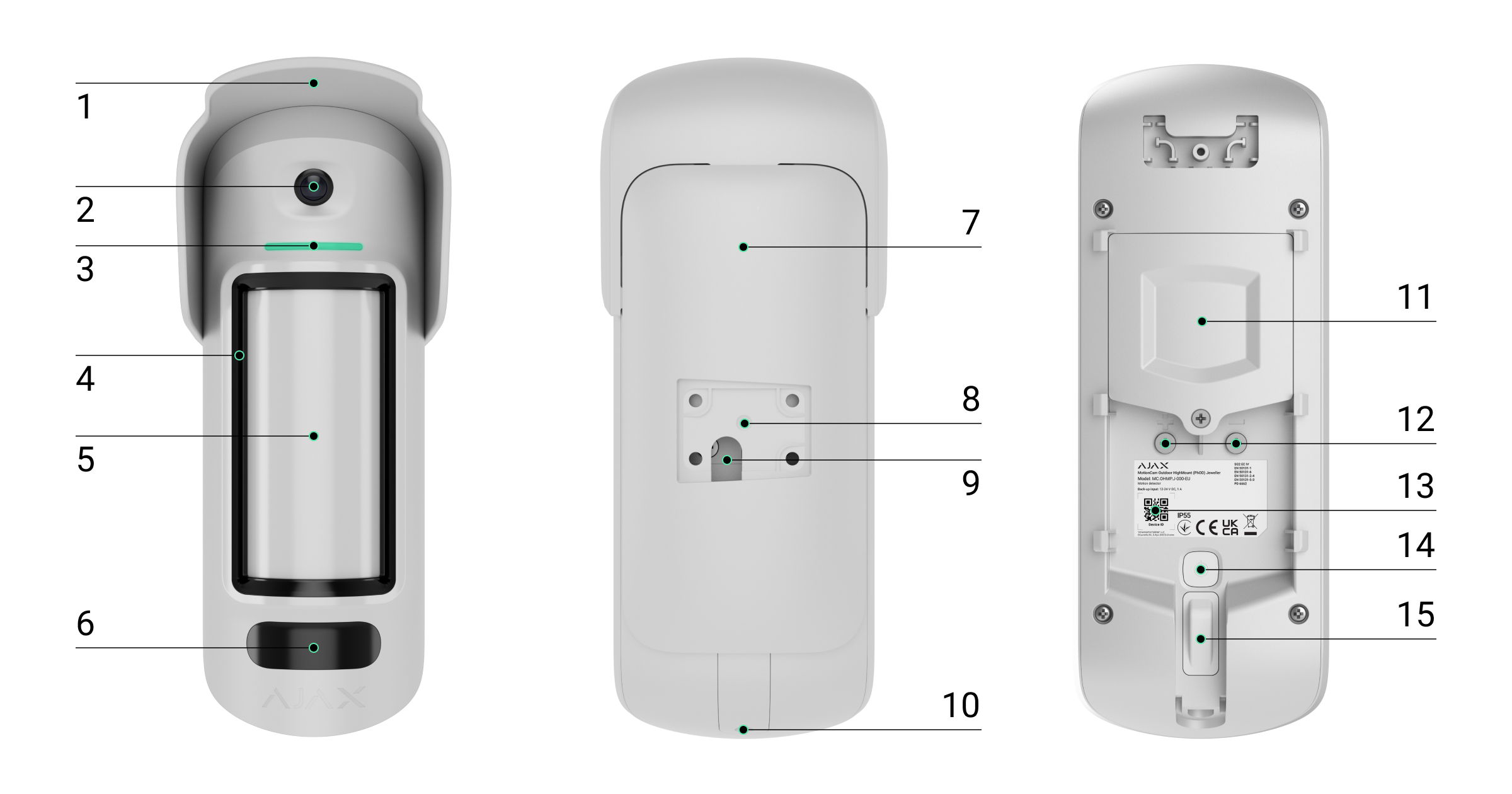
Detector
- A hood to protect the camera and anti-masking sensors from rain and snow.
- Camera.
- LED indicator.
- Masking sensor.
- Motion sensor lens.
- Infrared (IR) illumination. It is used to take photos in dark and low-light conditions.
- SmartBracket mounting panel. To remove the panel, slide it down.
- Recess for mounting the SmartBracket to the swivel mount.
- Hole for routing an external power supply cable.
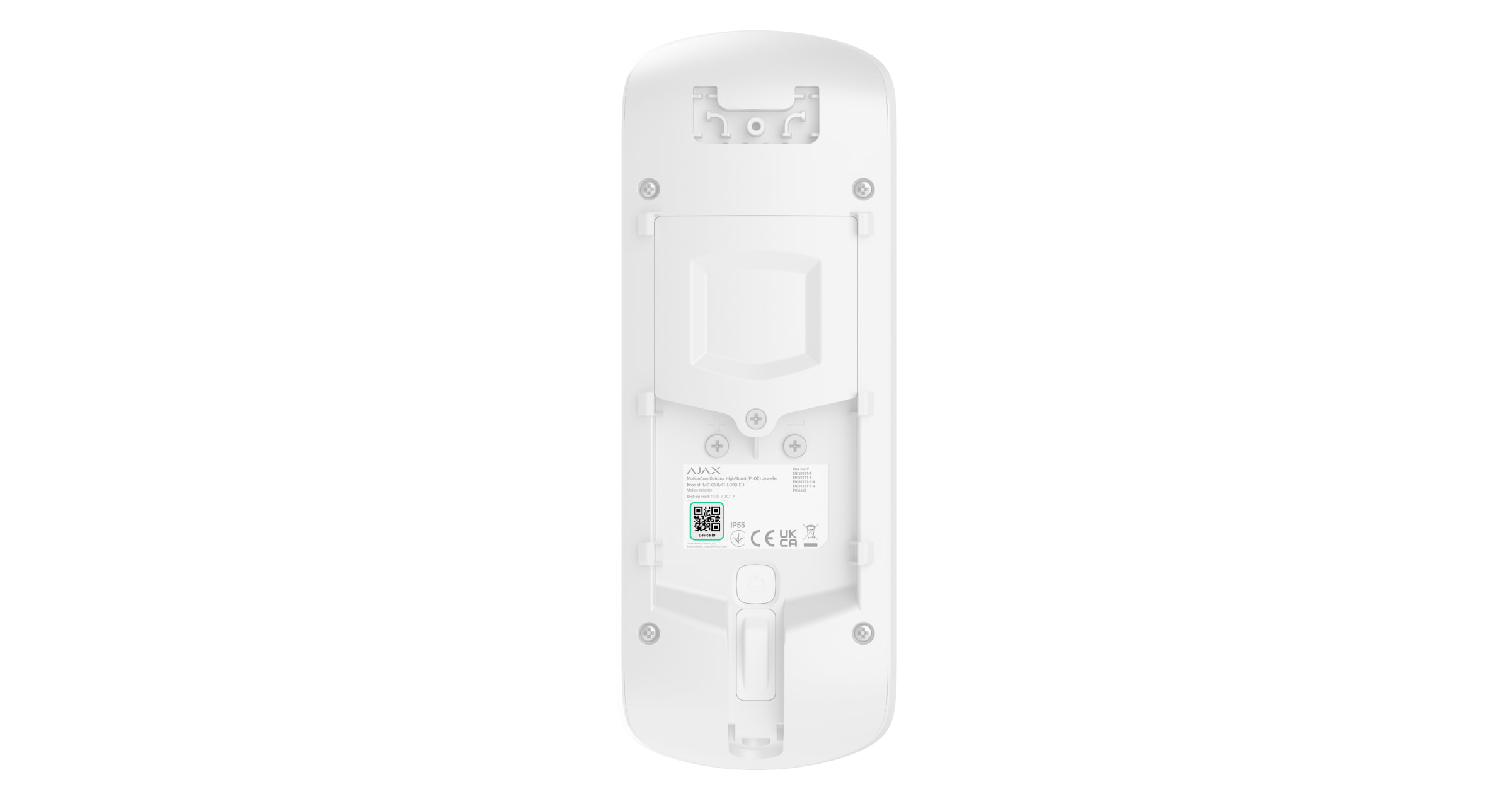
- Holding screw. It is used to secure the device to the SmartBracket mounting panel.
- Battery compartment cover.
- Terminals for connecting an external power supply.
- QR code containing the device ID. It is used to add the device to the hub.
- Power button.
- Tamper button.
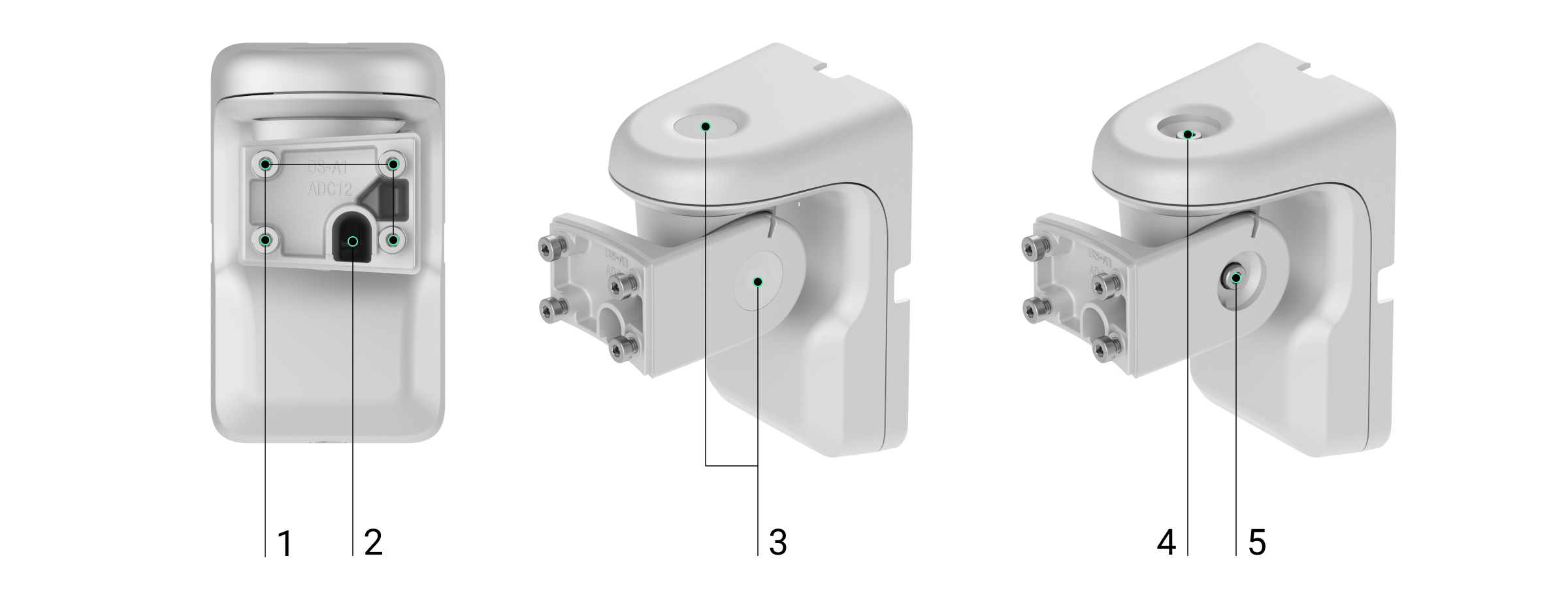
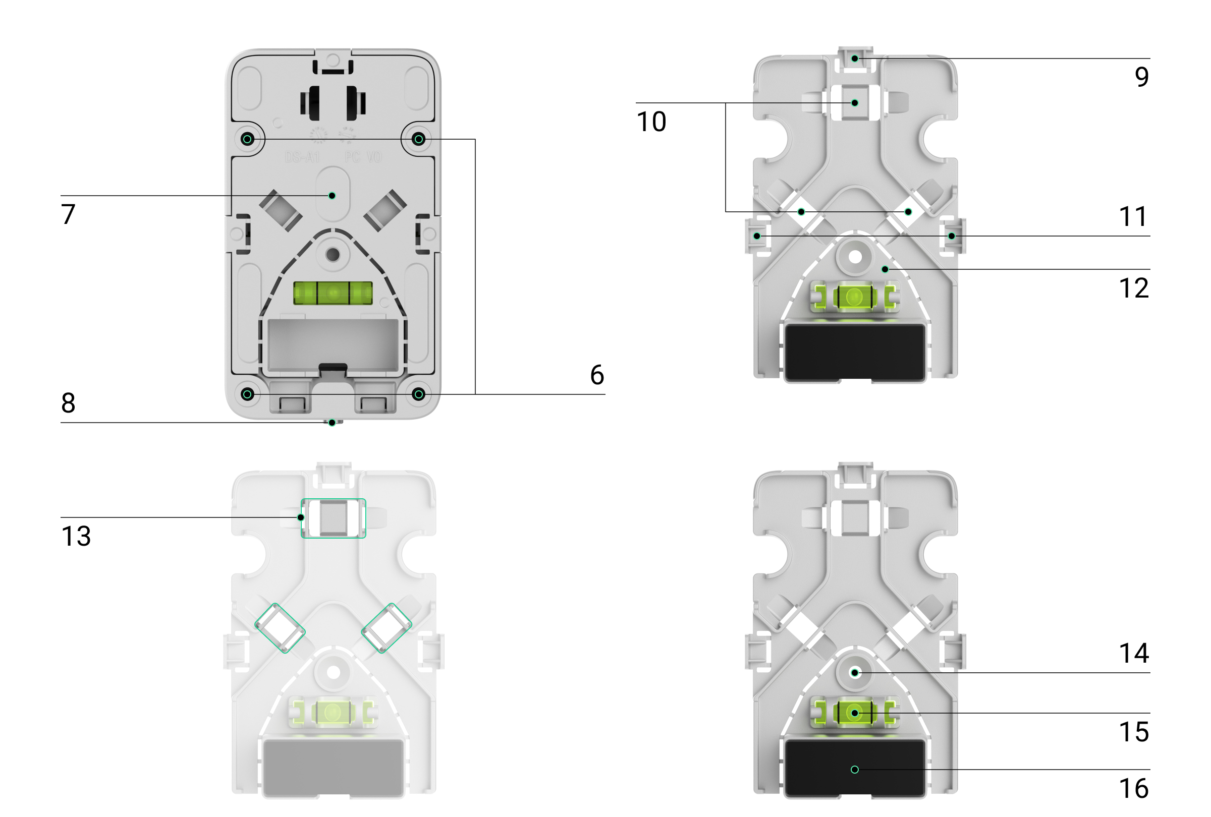
Swivel mount
- Fixing points for attaching the SmartBracket mounting panel to the swivel mount with screws.
- Conduit for routing an external power supply cable through the swivel mount.
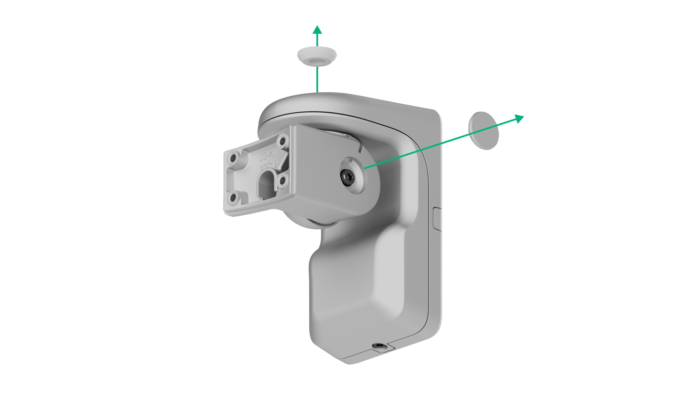
- Rubber sealing plugs to protect the screws that adjust the detector's positioning angles.
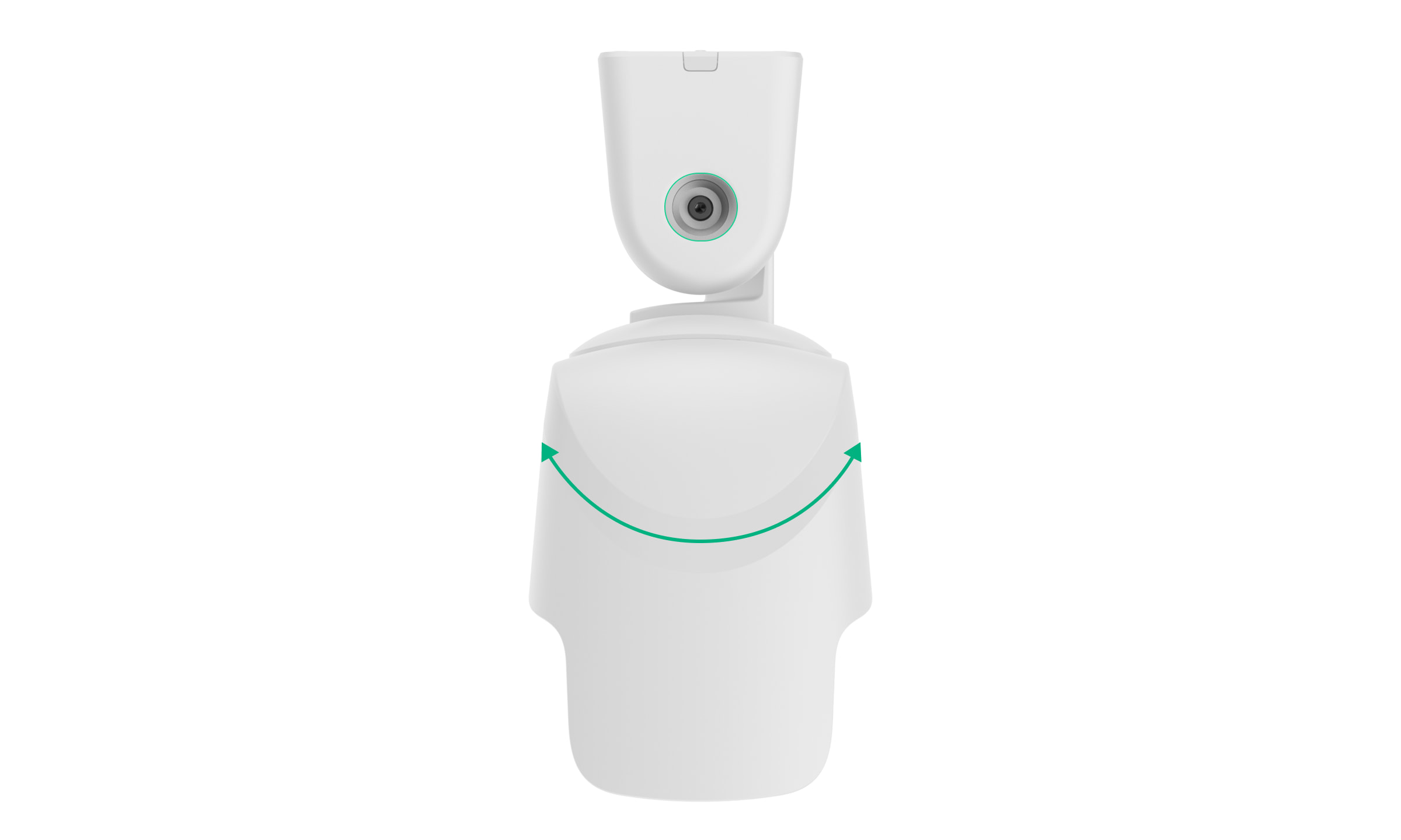
- Use the top screw to adjust and secure the horizontal position of the detector.
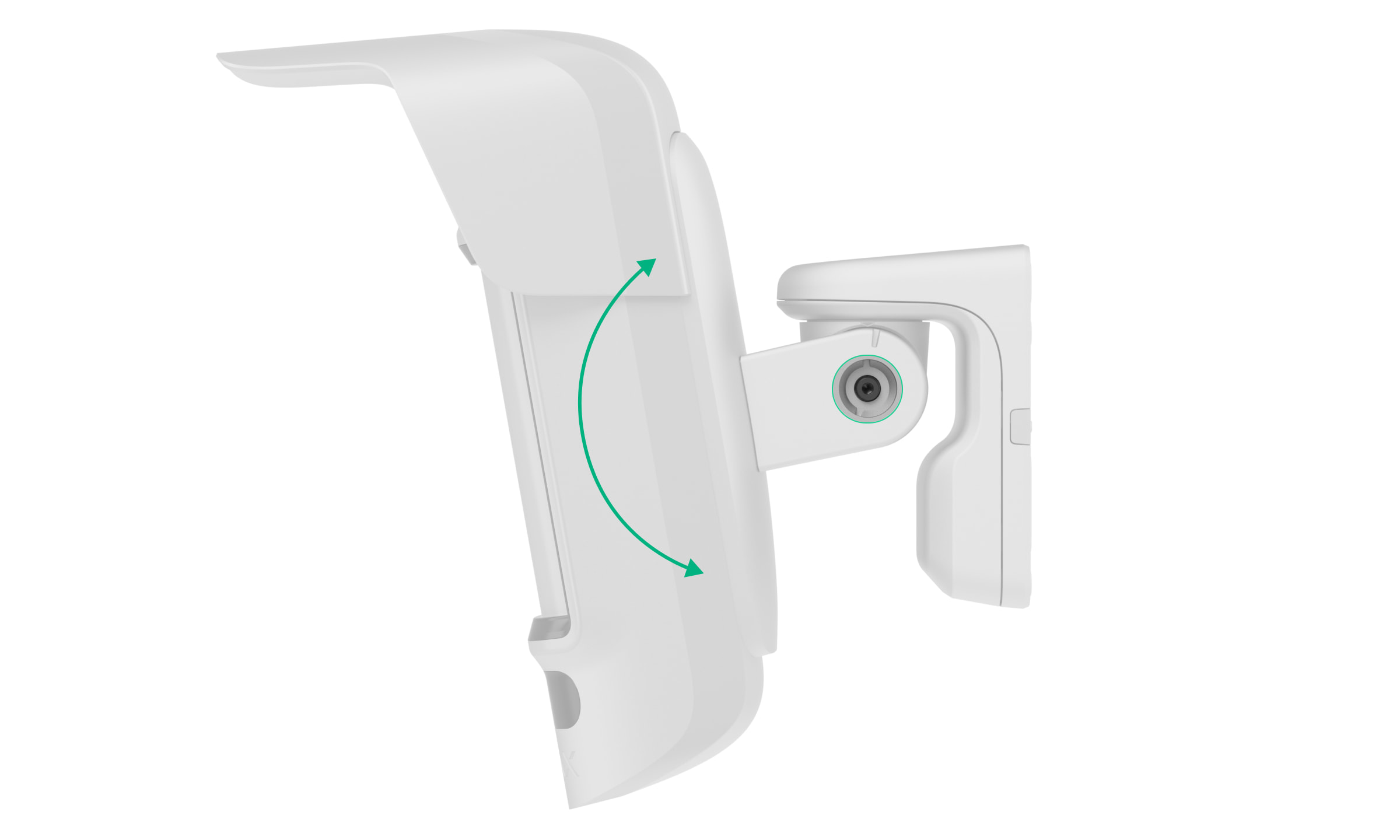
- A side screw to adjust and secure the tilt angle of the detector.
- Holes for attaching the swivel mount to the surface.
- Plastic panel of the swivel mount. It features a bubble level, a magnet, and cable management components.
- Holding screw. It is used to secure the components of the swivel mount.
- Perforated section of the plastic panel to route the cable from the top of the swivel mount.
- A hole to route the cable through the wall.
- Perforated sections of the plastic panel to route the cable from the sides of the swivel mount.
- A perforated section with a magnet on the plastic panel. It is used to trigger the device's magnetometer in the event of any attempt to tilt or move the detector or detach it from the surface. Do not break it off.
- Fasteners to secure the cables with ties.
- A hole for attaching the plastic panel to the surface.
- A bubble level to check the angle of inclination of the mount during installation.
- Magnet. It is used to trigger the device's magnetometer in the event of any attempt to tilt or move the detector or detach it from the surface.
Compatible hubs and range extenders
An Ajax hubw , OS Malevich 2.26 and later versions, is required for the device to operate.
Operating Principle
The MotionCam Outdoor HighMount (PhOD) Jeweller is a wireless motion detector that supports photo verification. It is equipped with two IR sensors, an additional K-band microwave sensor, a camera, and an anti-masking system.
The device detects motion using IR sensors by identifying moving objects with temperatures close to that of the human body. After detecting motion with the IR sensors, the detector initiates an additional RF scan of the detection zone using the built-in K-band microwave sensor to filter out false alarms.
When motion is detected, the MotionCam Outdoor HighMount (PhOD) Jeweller captures a series of images, allowing for a dynamic assessment of the situation on-site. This spares users from unnecessary anxiety and prevents security companies from dispatching patrols in response to false alarms.
In the event of an alarm, the detector immediately sends an alarm to the hub, activating the sirens connected to the system, triggering“ ” scenarios, and notifying users and the security company. All MotionCam Outdoor HighMount (PhOD) Jeweller alarms and events are recorded in the event feed of the Ajax apps.
Users and the monitoring company know exactly where movement is detected. The notifications include the name of the space (the name of the guarded facility), the device name, and the virtual room to which the device is assigned.
Protection against false alarms
The MotionCam Outdoor HighMount (PhOD) Jeweller uses the SmartDetect algorithm to prevent false alarms. This algorithm allows the detector to analyze the thermal image captured by the sensor, including the intensity of infrared radiation, the size of the heat spot, the time spent in the detection area, and other parameters.
After this stage, the detector performs additional RF scanning of the detection zone using a built-in K-band microwave sensor to eliminate false alarms caused by IR interference, such as air currents, heated curtains and blinds, fans, fireplaces, air conditioners, etc. Depending on the result, the alarm will be triggered or not.
Temperature Compensation
Due to temperature compensation, the detector responds to movement even if the temperature at the facility is close to human body temperature. Read more about temperature compensation inthe article at .
Anti-masking system
Masking is an attempt to block the detector's view. The MotionCam Outdoor HighMount (PhOD) Jeweller detects the following types of masking:
- Placing an obstacle in front of the detector’s motion-sensing area.
- Painting over the sensitive area of the detector's motion sensor.
- Taping over the sensitive area of the detector’s motion sensor.
The system notifies users and the security company’s monitoring station when an object is blocking the sensor. The maximum time for detecting an obstruction is up to 180 seconds (depending on the type of obstacle and the distance to it).
If the" " anti-masking feature ( ) is enabled, it is always active and works regardless of the security mode.
Jeweller and Wings data transfer protocols
Jeweller and Wings are wireless data transfer protocols that provide fast and reliable two-way communication between the hub and devices. The detector uses (Jeweller) to transmit alarms and events, and (Wings) to transmit photos and update the firmware.
Firmware Update
If a new firmware version is available for the MotionCam Outdoor HighMount (PhOD) Jeweller, the
Sending events to the monitoring station
The Ajax system can transmit alarms to the PRO Desktop monitoring app and the central monitoring station (CMS) in thefollowing formats: SurGard (Contact ID), SIA (DC-09), ADEMCO 685, and other protocols.
The MotionCam Outdoor HighMount (PhOD) Jeweller can transmit the following events:
- Motion alarm.
- Masking alarm.
- Alarm indicating that the device has been moved: the magnetometer has detected attempts to tilt or shift the detector or detach it from the surface.
- Tamper alarm. Tamper recovery.
- Loss and restoration of the connection to the hub.
- Permanent deactivation or activation of the device.
- One-time deactivation or activation of the device.
When an alarm is received, the operator at the security company’s monitoring station knows what has happened and exactly where to dispatch a rapid response unit. The addressability of Ajax devices allows events to be sent to the PRO Desktop or the CMS, including the device type, name, security group, and virtual room. The list of transmitted parameters may vary depending on the type of CMS and the selected communication protocol.
Photo Verification
Photo verification allows you to see what is happening at the secured site using a built-in camera. The device can take 1 to 5 images with a resolution of 320 × 240 pixels and up to 3 images with a resolution of 640 × 480 pixels.
With photo verification, you can receive visual confirmations of alarms from the MotionCam Outdoor HighMount (PhOD) Jeweller and other Ajax devices. You can also check on the situation—for example, to see what the children are doing, to make sure your pet is okay, or simply to monitor what’s happening at home.
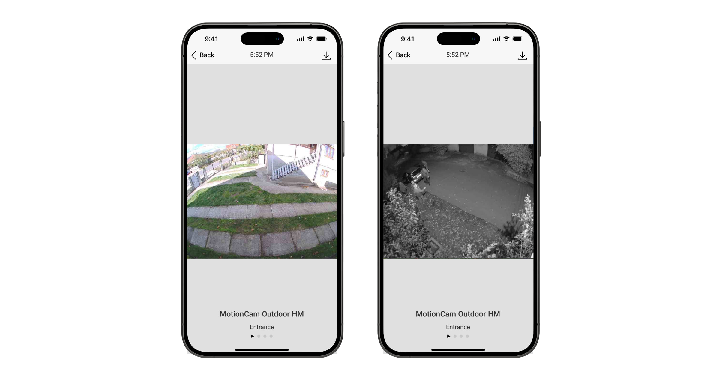
The detector features infrared illumination for shooting in the dark, which turns on in low-light conditions. The MotionCam Outdoor HighMount (PhOD) Jeweller takes black-and-white photos when shooting under these conditions.
There are several types of photo verification: photo upon alarm, photo on demand, photo by scenario, photo by schedule, and photo upon arming or disarming.
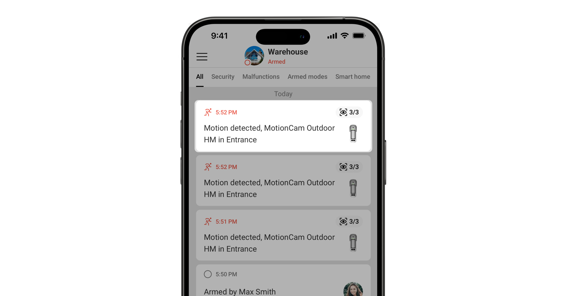
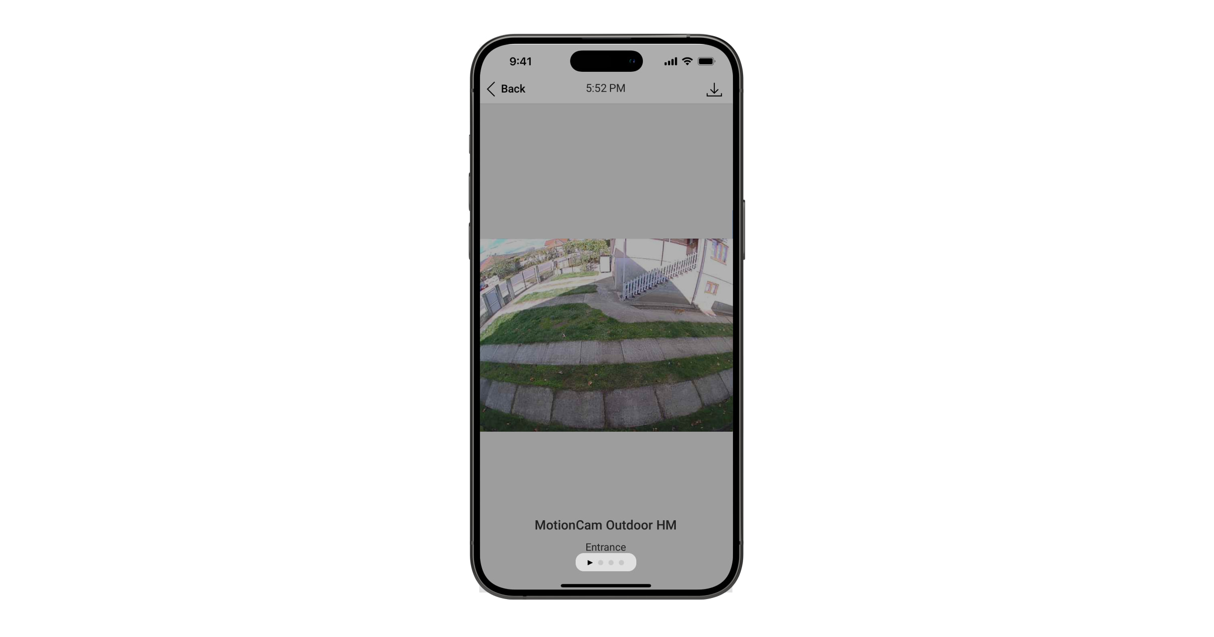
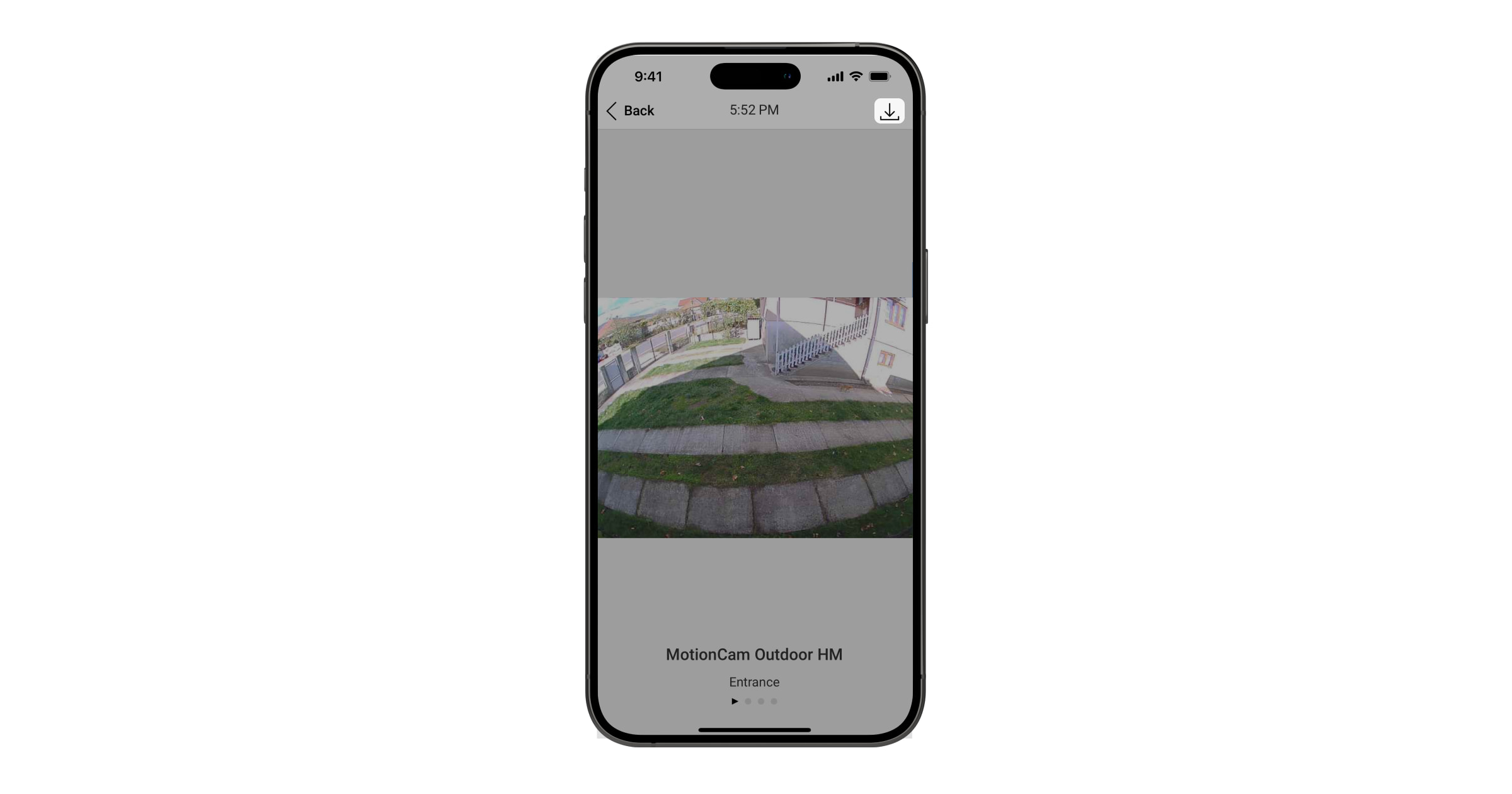
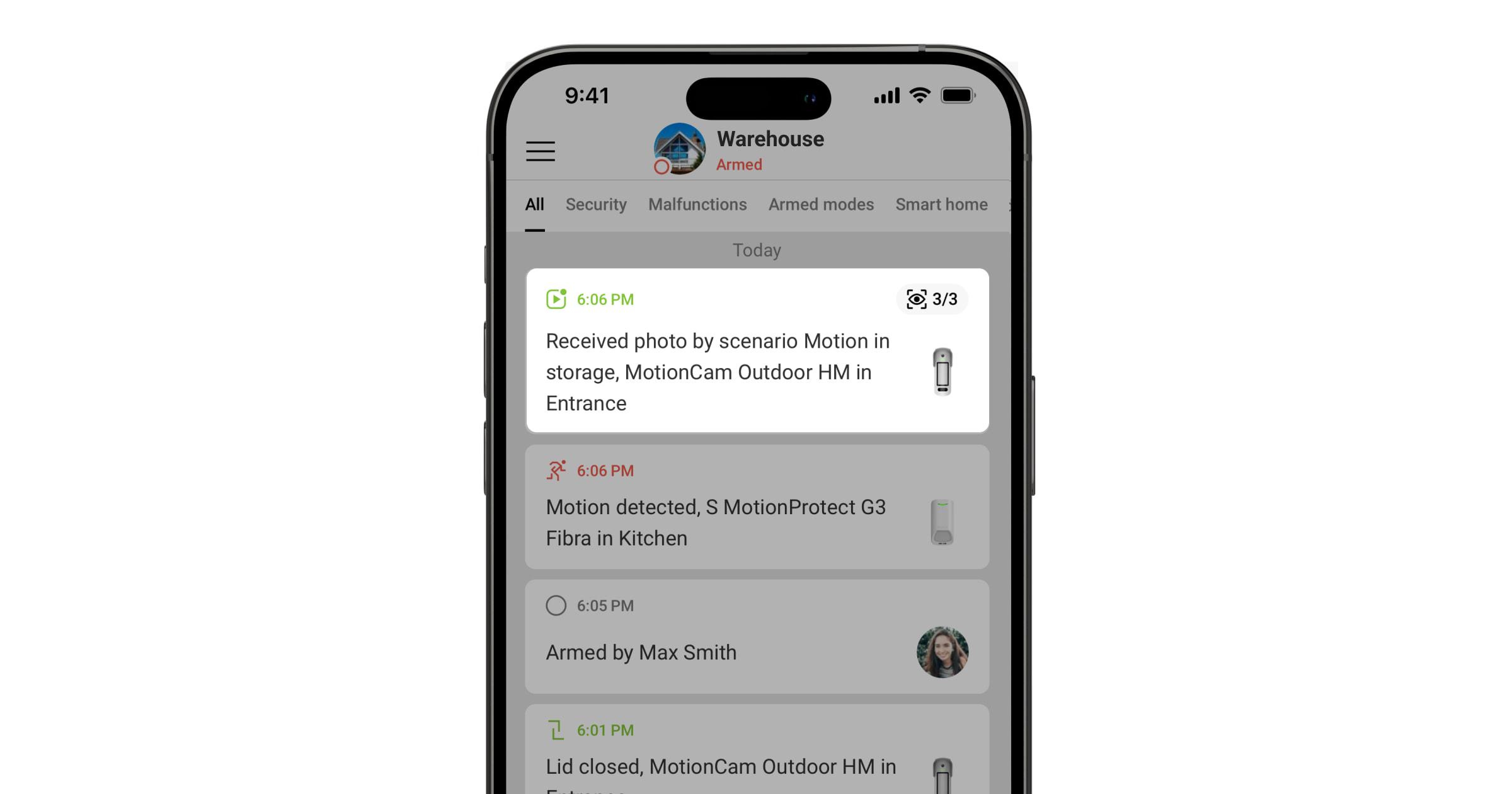
The photos can be displayed in the app as a single image or a series of animated images (if more than one photo is taken). The number of images in the series can be configured in Ajax apps. To view the received photos, tap the corresponding MotionCam Outdoor HighMount (PhOD) Jeweller notification in the event feed.
Users can view the images from the animated series frame by frame by swiping left.
You can save the photo verification result as a video or photo by tapping the download icon.
Photo by alarm
The detector takes photos via the alarm only if motion is detected and only when the system is armed. By default, the Photo by alarm feature is enabled for all detectors. The number of images and their resolution can be changed in the device settings. Photos taken via the alarm are available to all users with access to the event feed.
The detector does not switch to armed mode immediately. The switching time depends on the exit delay (specified in the device settings) and the hub–detector polling interval. The polling interval is specified in the Jeweller or Jeweller/Fibra settings; its default value is 36 seconds. In the first case, the delay is set by a user or a PRO with admin rights. In the second case, the delay occurs because the hub takes one polling interval to notify the detector of the security mode change.
Photo on Demand
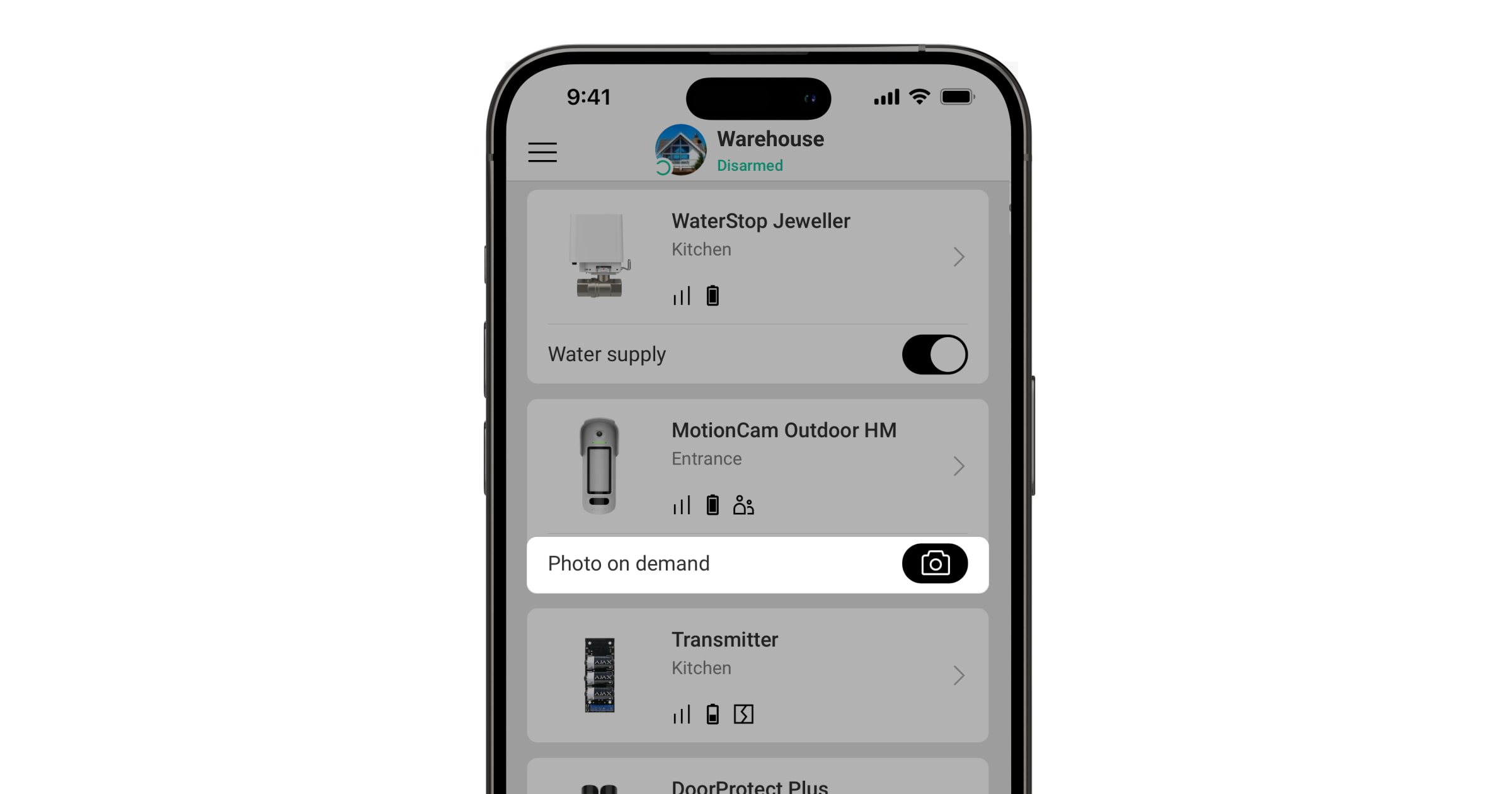
The" " "Photo on Demand feature allows users to take photos using the built-in cameras of detectors that support photo verification. With this feature, you can check what’s happening at the site: see what the children are doing, check if your pet is OK, or simply monitor the situation at home. Depending on the settings, photos can be taken at any time or when the MotionCam Outdoor HighMount (PhOD) Jeweller is armed.
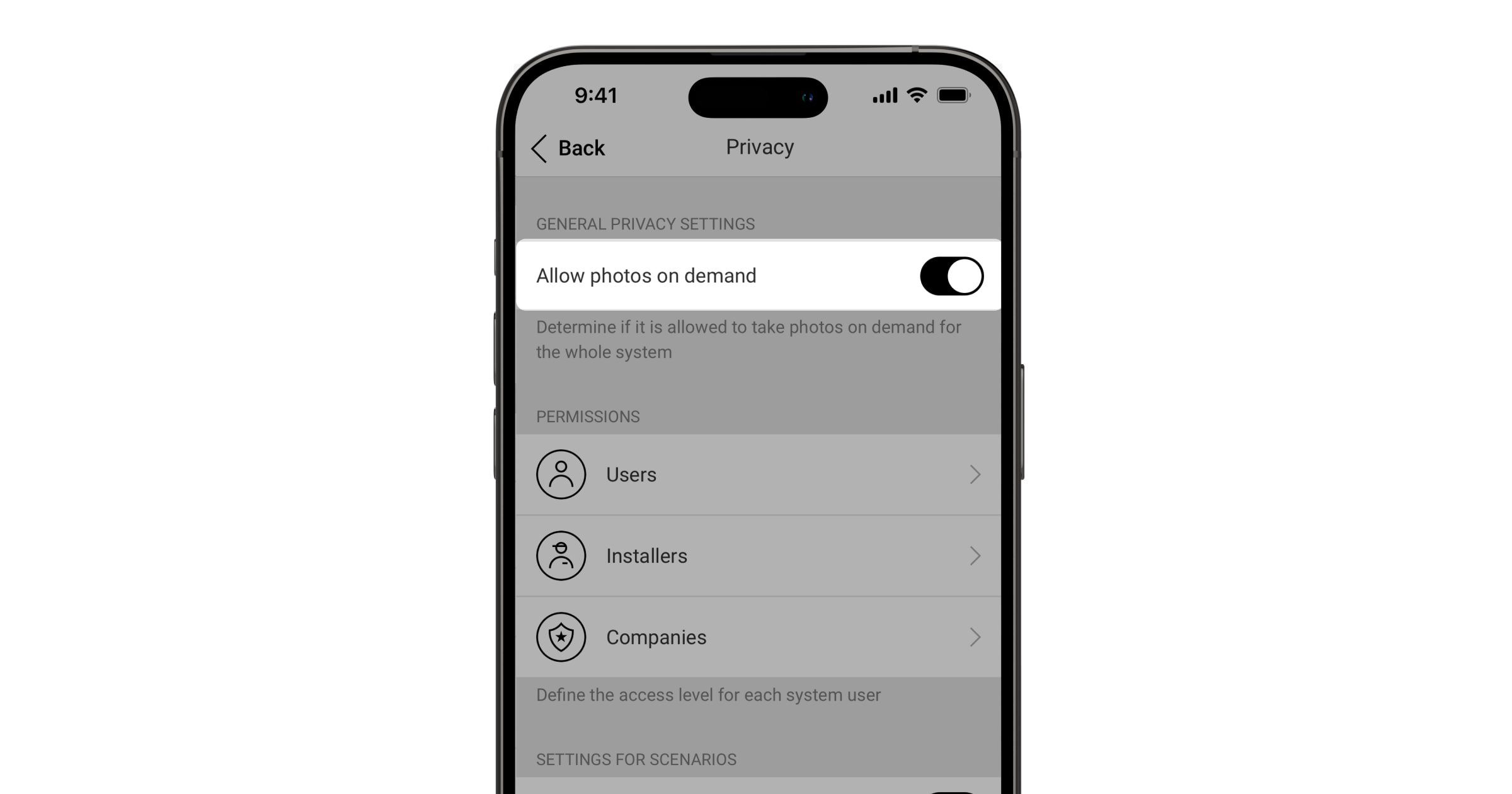
By default, the" " and "Photo on Demand features are disabled for all users. Users with the right to manage privacy settings (space settings, the" " section under"Privacy ) determine who can take and view photos on demand and which detectors that support photo verification can take pictures. PRO users cannot manage privacy settings, but they can take photos on demand if they have been granted such permission.
Privacy settings do not apply to photos taken by detectors that are triggered in the event of an alarm. All system users who have access to the event feed can view the photos taken in the event of an alarm.
Photos on demand are not sent to the security company's monitoring station.
PRO Desktop users can take and view photos on demand only from their personal account if an administrator has granted them the appropriate access rights. Taking and viewing photos on demand is not available for the security company profile in the PRO Desktop app.
Photo by scenario
Photo by Scenario feature allows you to create a scenario for motion detectors that support photo verification. These detectors will take pictures when alarms are triggered by specified Ajax devices.
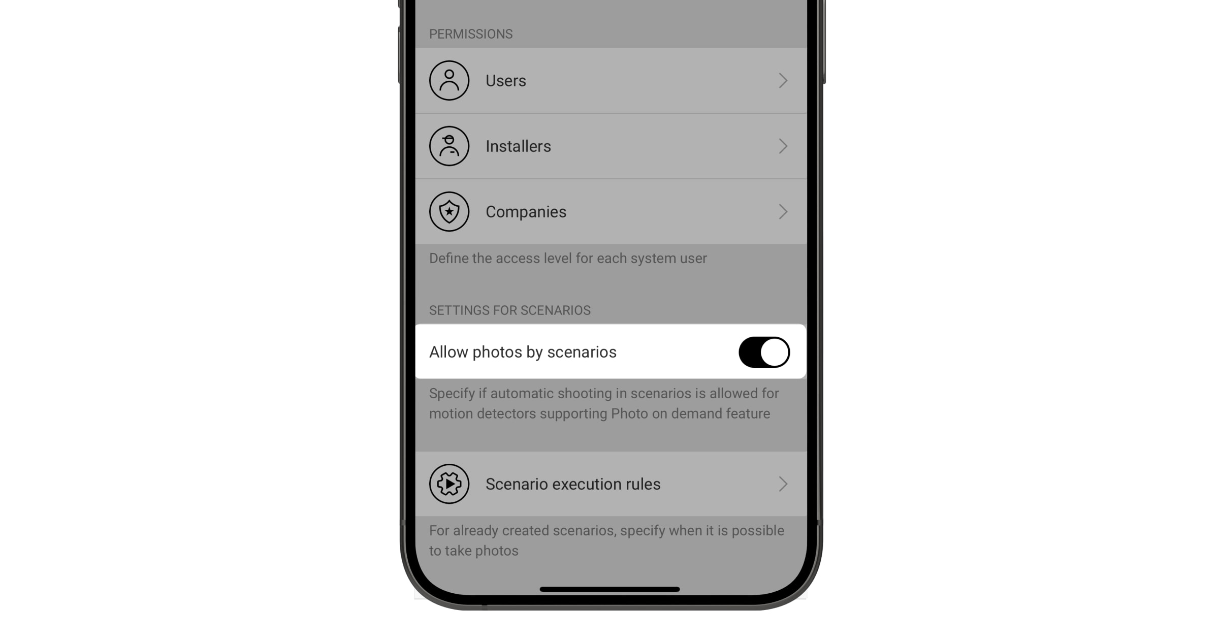
By default, the" : Allow photos by scenarios option is disabled for all detectors. An administrator or a user with access to privacy settings can enable it.
In the system settings, you can also specify exactly when a detector that supports photo verification can take photos based on a scenario: always, or when the device is armed.
Photos by scenario are available to all system users who have access to the event feed. The event indicating that a photo was taken after an alarm from specified devices is sent to the security company’s monitoring station via SIA DC-09 (SIA-DCS) and other proprietary protocols. The event code is 730.
If the CMS software supports photo verification, photos organized by scenario are available to CMS engineers. Photos organized by scenario are also available in the PRO Desktop app.
Photos by scenario will not be sent to the CMS if only adirect connection to the monitoring station is used ( ).
Photo by schedule
Photo by Schedule feature allows you to create a scenario for motion detectors that support photo verification. These detectors will take photos according to a schedule.
Before creating a scheduled scenario, enable the option“ : Allow photos by scenarios” . An administrator or a user with access to privacy settings can enable this option.
You can specify exactly when a detector that supports photo verification can take pictures according to a scheduled scenario: always, or when it is armed.
Photos taken according to a schedule are available to all system users who have access to the event feed. The event indicating that a photo has been taken is sent to the CMS via SIA DC-09 (SIA-DCS) and other proprietary protocols. The event code is 731.
If the CMS software supports photo verification, scheduled photos are available to CMS engineers. These photos are also available in the PRO Desktop app.
Photos taken on a schedule are not sent to the CMS if only adirect connection with the monitoring station is used viaa " ."
Photo by arming/disarming
Photo by arming/disarming feature allows users to receive photos from a built-in camera when the security state changes. With this feature, you can check the situation at the facility when the system is armed, disarmed, or switched to Night mode.
Before creating an arming/disarming scenario, enable the" " and the "Allow photos by scenarios options. A space admin or a user with access to privacy settings can enable this option.
The“ ” feature,which takes photos when arming or disarming , is available in the hub’s settings with OS Malevich 2.29 and later. This feature allows you to configure the conditions under which the selected detectors take photos: when arming, when disarming, when Night mode is enabled, or when Night mode is disabled. You can also choose whether to include or ignore entry/exit delays.
Photos taken when arming or disarming the system are available to all system users with access to the event feed. The event indicating that a photo was taken is sent to the CMS via SIA DC-09 (SIA-DCS) and other proprietary protocols. The event code is 732.
If the CMS software supports photo verification, CMS engineers can access photos by arming or disarming the system. These photos are also available in PRO Desktop.
Photos taken when arming or disarming the system will not be sent to the CMS if only adirect connection to the monitoring station— —is used.
Selecting the installation site
The MotionCam Outdoor HighMount (PhOD) Jeweller is suitable for securing the grounds of protected facilities, such as private homes, parking lots, construction sites, unheated buildings, etc. The device can be installed both outdoors and indoors.
The device is designed to be installed at a height of 2–4 m. The device should be mounted on a flat, stable surface, such as the wall of a house or a solid fence. Installing the device on a shaky (unstable) surface will result in false alarms.
Depending on the installation height, the tilt angle and horizontal position of the device must be adjusted using the swivel mount. This is necessary to ensure that the detector’s motion sensors and camera have the correct fields of view. The direction of the detector’s sensors should be perpendicular to a potential intrusion path to the site.
When choosing where to install the MotionCam Outdoor HighMount (PhOD) Jeweller, consider the factors that affect its operation:
- Jeweller and Wings signal strength.
- Motion detection area.
The distance between the MotionCam Outdoor HighMount (PhOD) Jeweller and another detector equipped with a K-band microwave sensor should be at least 20 cm.
- The presence of objects or structures that can obstruct the detector’s line of sight.
Take the installation recommendations into account when developing a system project. Only specialists should design and install Ajax systems. A list of recommended partners isavailable here.
Signal strength
Signal strength is determined by the number of undelivered or corrupted data packets over a certain period of time. The
- three bars — excellent signal strength;
- two bars — good signal strength;
- one bar — low signal strength; stable operation is not guaranteed;
- crossed-out icon — no signal.
Check the signal strength of the Jeweller and Wings before final installation. If the signal strength is one bar or zero bars, we cannot guarantee that the device will operate reliably. Consider moving the device, as adjusting its position by as little as 20 cm can significantly improve the signal strength. If the signal remains weak or unstable after moving the device, consider using a radio signal range extender.
Refer to the" " section on "Functionality Testing to learn how to run Jeweller and Wings signal strength tests.
Motion Detection Zone
The detector's location determines the area to be monitored and the effectiveness of the security system. When selecting the installation location, consider the direction of the detector's sensors and the camera, the viewing angles, and any obstacles in the detector's line of sight.
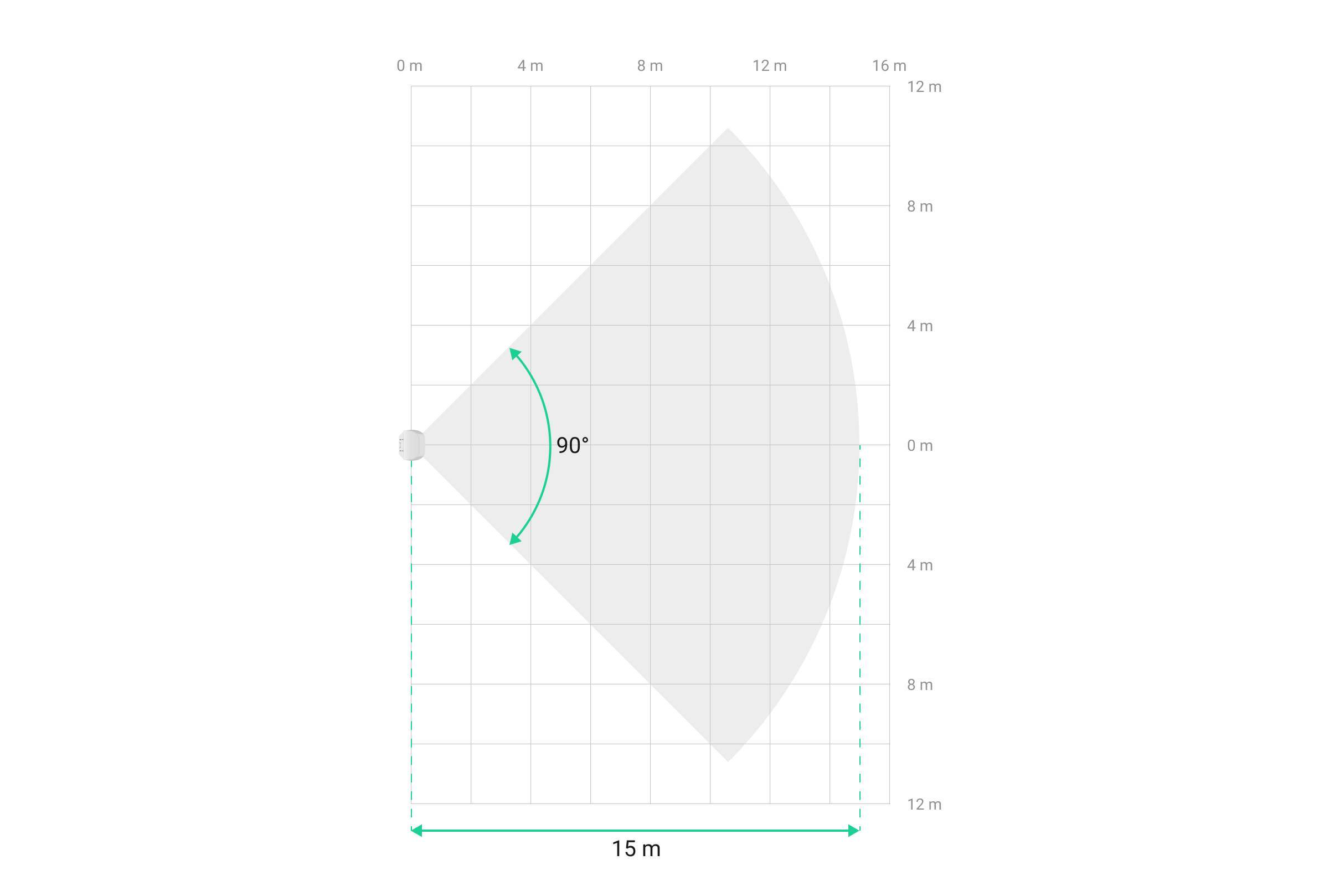
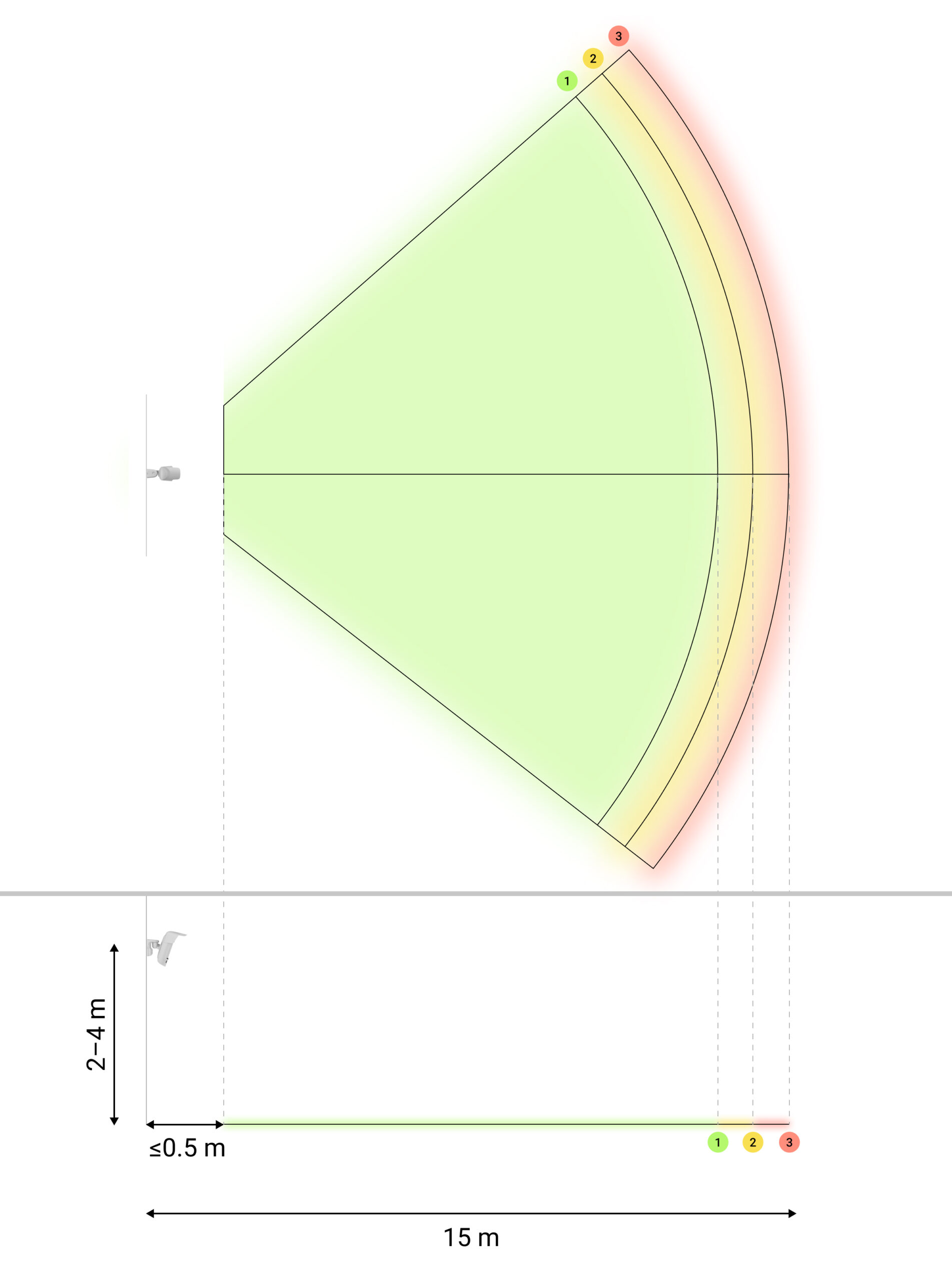
The MotionCam Outdoor HighMount (PhOD) Jeweller detects movement at a distance of up to 15 m. The detector sensors should be positioned perpendicular to the intended entry path to the site. Ensure that no structures or objects block the detector’s line of sight.
Horizontal Characteristics of the Motion Detection Area
When installing the detector, take a test photo of the motion detection zone and perform the Detection Zone Test. This allows you to verify the device's operation and accurately determine the sector in which the device detects motion. Refer to the Functionality Testing section to learn how to run the tests.
Do not install the detector
- In places where objects or structures can block the detector's view. For example, behind a tree or a column.
- In places where glass structures can obstruct the detector’s view, the device does not detect movement behind the glass.
- In front of water reservoirs or pools, if they are located within the detector's detection zone.
- Near any sources of magnetic fields, such as electric motors for automatic gates, magnetic locks, power cables, etc. Such sources may trigger the device's magnetometer and cause false alarms indicating that the device has been moved.
Near other detectors equipped with K-band microwave sensors. The minimum distance between devices should be at least 20 cm. Otherwise, detection quality may be reduced, or false alarms may be triggered due to wave interference from the K-band microwave sensors.
- In areas with low or unstable Jeweller or Wings signal strength.
Closer than 1 m to the hub or radio signal range extender.
Installation
Before installing the MotionCam Outdoor HighMount (PhOD) Jeweller, make sure you have chosen the best location that meets the requirements of this manual.
Do not install the device near any sources of magnetic fields. If there is a magnetic source nearby, adjust the Magnetic sensor sensitivity in the device settings or move the device to a different location. Otherwise, this may cause false alarms indicating that the device's position has changed.
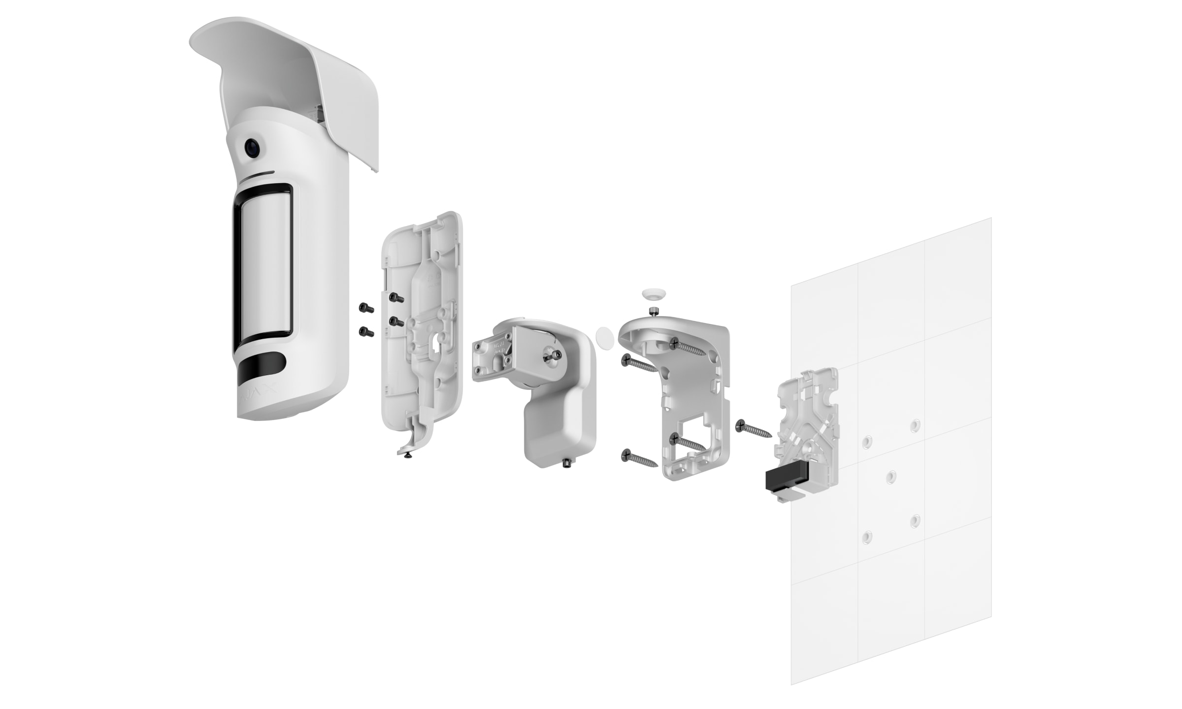
The MotionCam Outdoor HighMount (PhOD) Jeweller is designed to be installed using a swivel mount only. Installing the device on a swivel mount allows you to adjust the tilt angle and horizontal position of the detector and ensures advanced tamper protection with a built-in magnetometer.
To install the device:
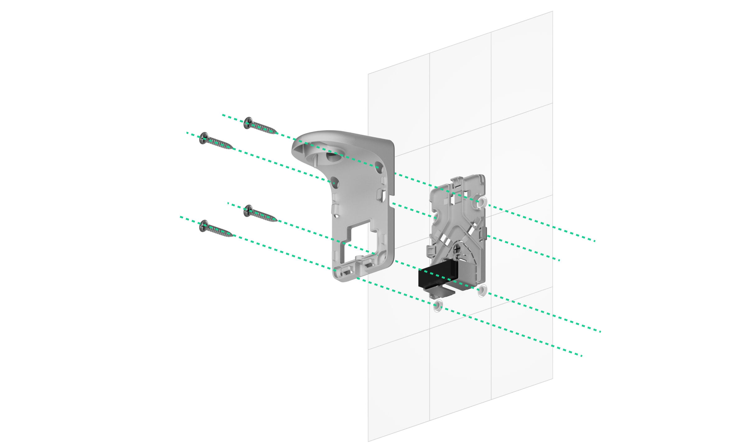
- Remove the plastic panel from the swivel mount. If you plan to connect the external power supply, carefully break out the corresponding perforated section to route the cable from the top, back, or sides. For more information, see the" " section under"Connecting an external power supply .
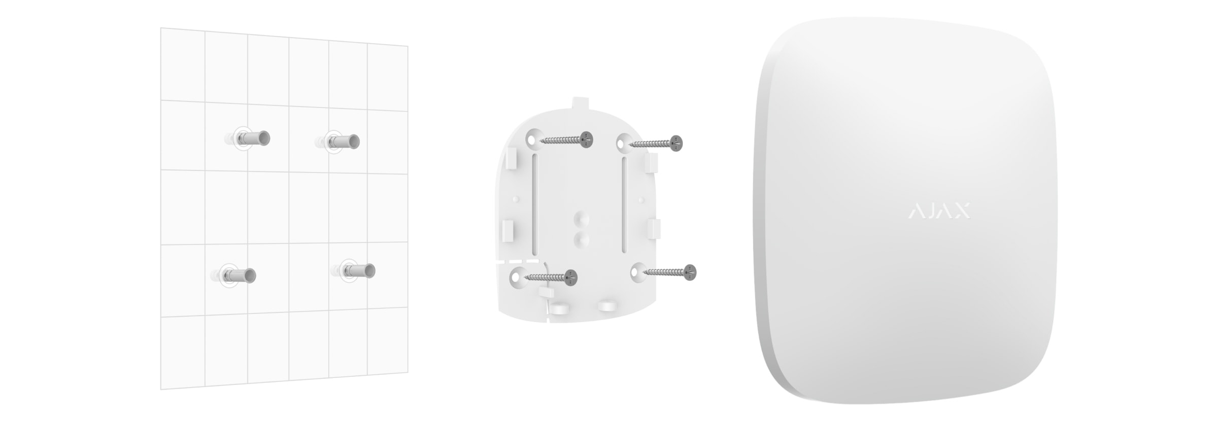
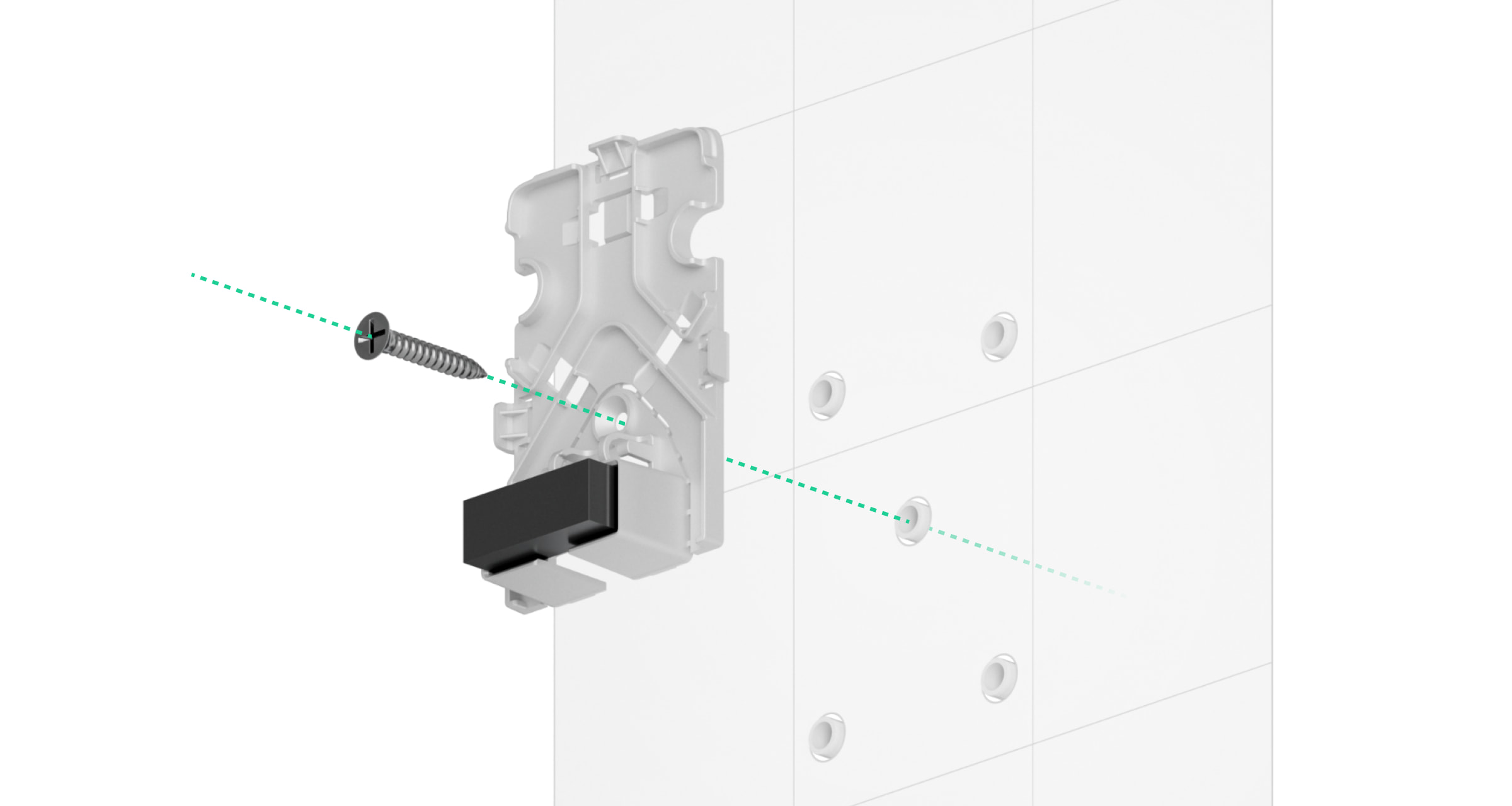
- Attach the plastic panel to the surface using the screw provided.
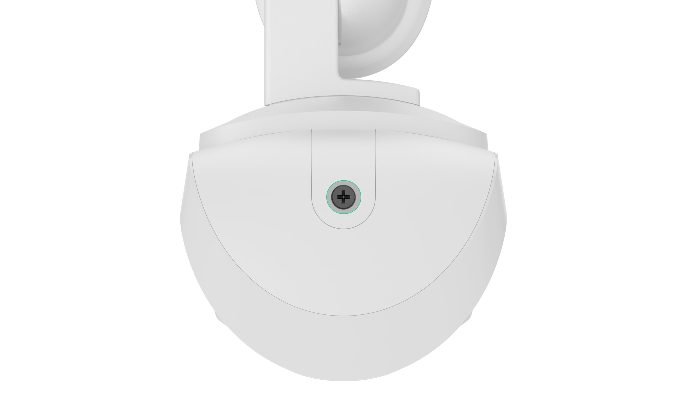
- Remove the rubber sealing plugs that protect the top and side screws of the swivel mount. Do not use sharp or pointed tools to avoid damaging the sealing plugs.
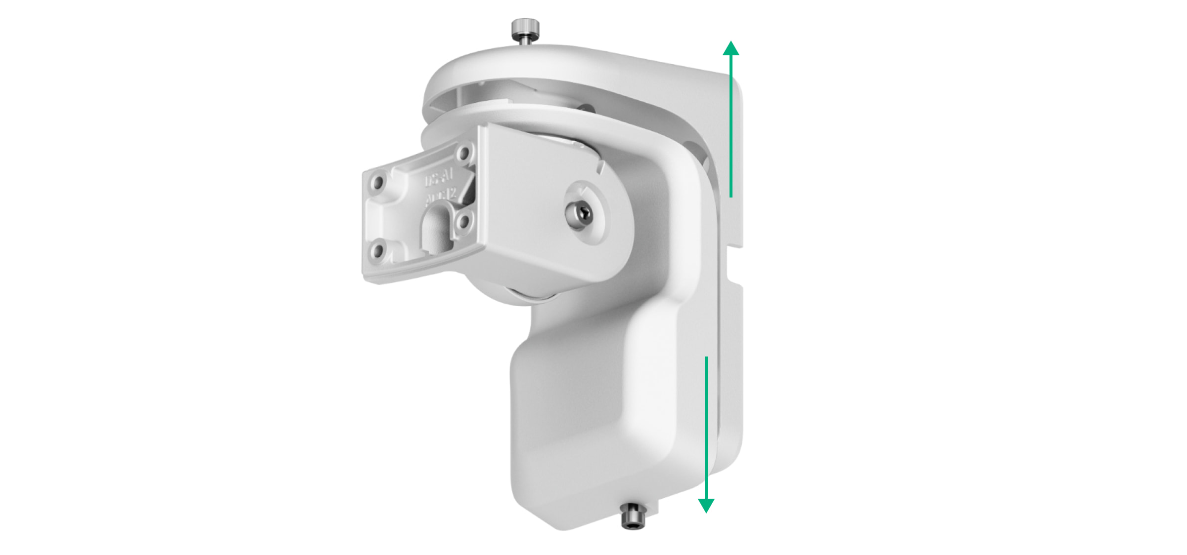
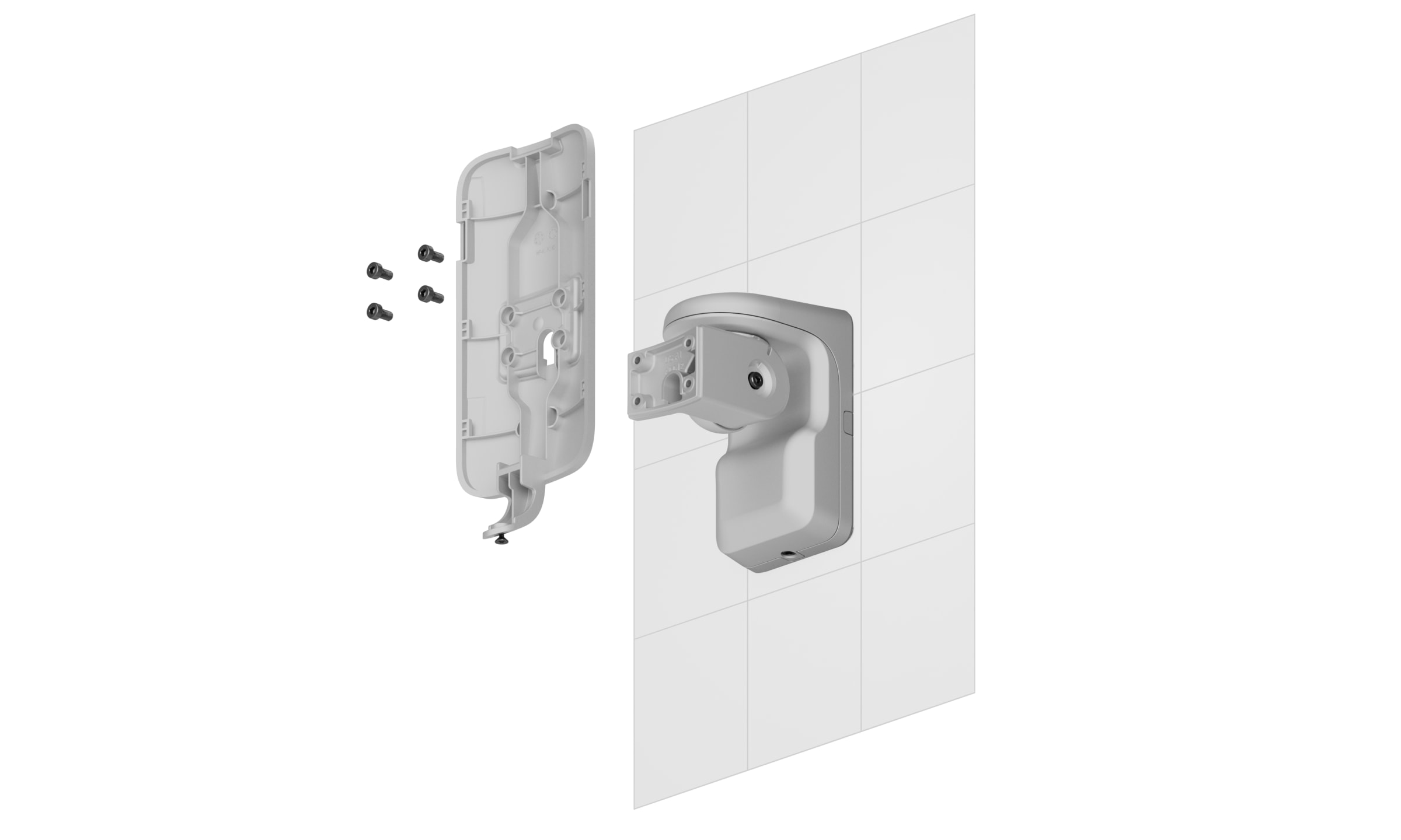
- Unscrew the top screw and the retaining screw at the bottom of the swivel mount. Disassemble the rear part of the swivel mount by sliding it upward.
If you are connecting an external power supply, see the "Connecting an External Power Supply" section to learn how to route the cable through the swivel mount.
- Place the rear part of the swivel mount over the plastic panel and secure it to the surface using the screws provided. Use all mounting points.
- Attach the front part of the swivel mount to the rear part, and tighten the top screw and the holding screw at the bottom.
- Remove the SmartBracket mounting panel from the detector. First, unscrew the retaining screw, then slide the panel down.
- Attach the SmartBracket mounting panel to the swivel mount and secure it with the included screws. Use all mounting points.
- Add the detector to the system.
- Attach the hood to the detector.
- Place the detector on the SmartBracket mounting panel.
- Loosen the top screw on the swivel mount, adjust the horizontal position of the detector's field of view, and then tighten the top screw.
- Loosen the side screw on the swivel mount, adjust the detector’s tilt angle, then tighten the side screw.
The tilt angle depends on the detector's installation height. To adjust the detector's field of view correctly, we recommend setting the following tilt angle relative to the detector's installation height:
Installation height Tilt angle 2.0 m 15.0° 2.2 m 15.9° 2.4 m 16.8° 2.6 m 17.7° 2.8 m 18.6° 3.0 m 20.0° 3.2 m 20.4° 3.4 m 21.3° 3.6 m 22.2° 3.8 m 23.1° 4.0 m 24.0° - Run the to perform functional testing.
- If the tests are successful, make sure the top and side screws on the swivel mount are securely tightened, and install the rubber sealing plugs that protect these screws.
- Remove the detector from the SmartBracket mounting panel and reinstall it to begin calibrating the magnetometer and masking sensors. To ensure proper calibration, make sure there are no obstacles in front of the detector and that it is not moved.
Calibration begins automatically once the detector is installed on the SmartBracket mounting panel.
- Tighten the retaining screw on the bottom of the detector housing. The screw is necessary to ensure a more secure fastening and to prevent the device from being quickly disassembled.
Connecting an External Power Supply
When connecting an external power supply and using the MotionCam Outdoor HighMount (PhOD) Jeweller, follow the general electrical safety regulations for the use of electrical appliances, as well as the requirements of applicable laws and regulations on electrical safety.
The MotionCam Outdoor HighMount (PhOD) Jeweller is equipped with terminals for connecting a 12–24 V⎓ power supply.
When an external power source is connected, the pre-installed batteries serve as a backup power source. Do not remove them while connecting the power supply.
Before installing the device, check the wires for any damage to the insulation. Use only a grounded power source. Do not disassemble the device while it is energized. Do not use the device with a damaged power cord.
To connect an external power supply:
- Disconnect the external power supply cable.
- Remove the detector and swivel mount if they have already been installed.
- Remove the plastic panel from the swivel mount. Carefully break out the corresponding perforated section to route the cable from the top, back, or sides.
- Remove the rubber sealing plugs that protect the top and side screws of the swivel mount. Do not use sharp or pointed tools to avoid damaging the sealing plugs.
- Unscrew the top screw and the retaining screw at the bottom of the swivel mount. Disassemble the rear part of the swivel mount by sliding it upward.
- Route the cable inside the detector through the following components:
- The plastic panel of the swivel mount
- The rear part of the swivel mount
- The front part of the swivel mount
- The SmartBracket mounting panel
- Connect the cable to the terminals, making sure to observe the polarity (marked on the plastic). Secure the wires firmly to the terminals.
- Install the swivel mount and the detector on the surface according to steps 5–16 described in the" " section ofInstallation .
- Turn on the external power supply.
Once the external power supply is connected, the The "External power parameter in the device states changes its status to Connected.
Adding to the system
The hub and the device, which operate on different radio frequencies, are incompatible. The device's radio frequency range may vary by region. We recommend purchasing and using Ajax devices in the same region. You can check the range of operating radio frequencies with the technical support service.
Before adding a device
- Install an Ajax app.
- Log in to your account at or create a new one.
- Select a space or create a new one.
- Add at least one virtual room.
- Add a -compatible hub to the space. Make sure the hub is turned on and has internet access via Ethernet, Wi-Fi, and/or a mobile network.
- Check the status in the Ajax app to make sure the system is disarmed and the hub isn't starting an update.
Only a PRO or a space admin with the necessary permissions to configure the system can add a device to the hub.
Adding to the hub
- Open an Ajax app. Select a space to which you want to add the device.
- Go to the" " tab under "Devices
and tap" " "Add device." - Assign a name to the device.
- Scan the QR code or enter the device ID manually. A QR code containing the ID is located on the device housing. It is also printed on the device packaging.
- Select a virtual room and a security group (if Group mode is enabled).
- Go to Add, and the countdown will begin.
- Turn on the device by holding down the power button for 3 seconds.
Once added to the hub, the device will appear in the list of hub devices in the Ajax app. The update frequency for device statuses in the list depends on the settingsfor Jeweller or Jeweller/Fibra and is 36 seconds by default.
If the connection fails, try again in 5 seconds. If the maximum number of devices has already been added to the hub, you will receive an error message when you try to add more.
The MotionCam Outdoor HighMount (PhOD) Jeweller works with only one hub. When paired with a new hub, it stops sending events to the old one. After the device is added to a new hub, it will not be automatically removed from the old hub's device list. This must be done through the Ajax app.
Functionality Testing
The Ajax system offers several types of tests to help you choose the correct installation location for the devices. For the MotionCam Outdoor HighMount (PhOD) Jeweller, the following tests are available:
- Motion detection area test — to take a test photo to check the detector’s field of view. The photo helps you adjust the detector’s tilt angle and horizontal position correctly.
- Jeweller signal strength test — to determine the signal strength and stability between the hub (or the radio signal range extender) and the device via the wireless Jeweller data transfer protocol at the device installation site.
- Wings signal strength test — to determine the signal strength and stability between the hub (or the radio signal range extender) and the device via the wireless Wings data transfer protocol at the device's installation site.
- Detection zone test — to check how the detector responds to movement and masking at the installation site.
- Signal attenuation test — to decrease or increase the power of the radio transmitter; to check the stability of communication between the device and the hub, the changing conditions at the site are simulated.
Icons
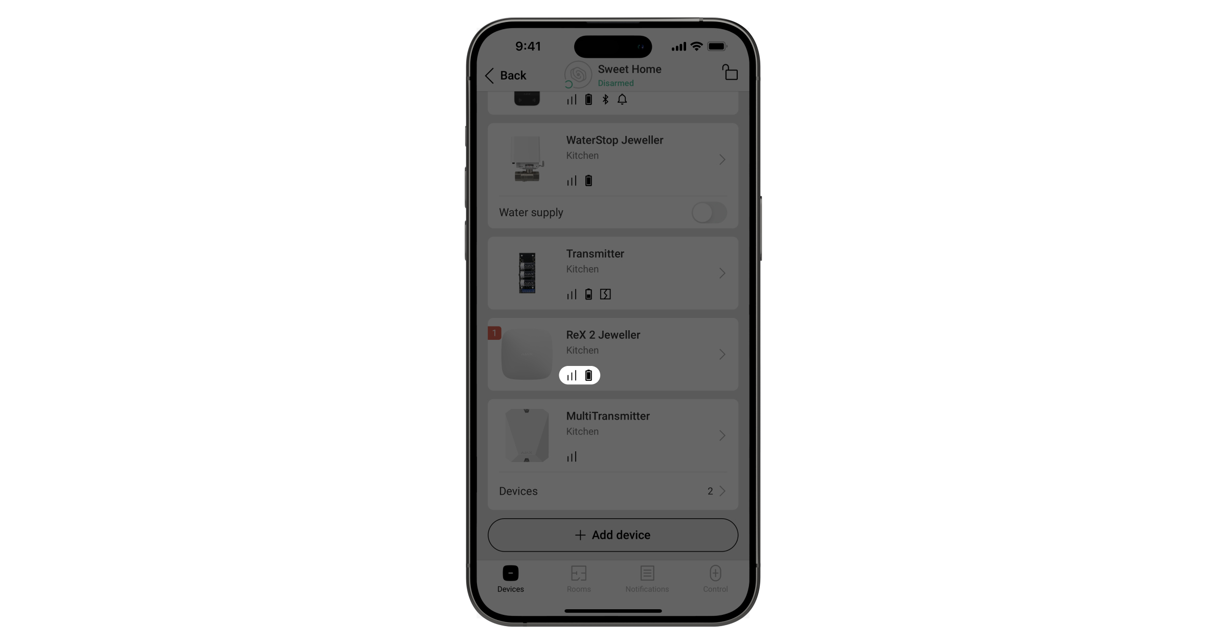
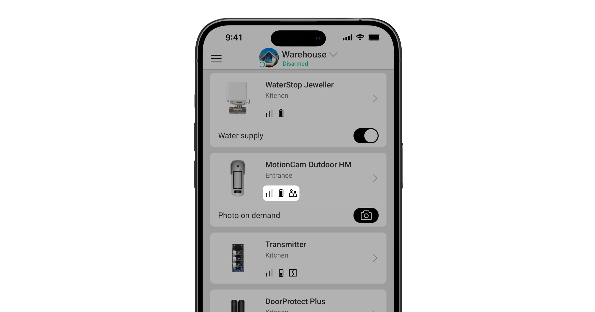
Icons in an Ajax app display some of the MotionCam Outdoor HighMount (PhOD) Jeweller states. You can view the icons in the" " tab under "Devices
| Icon | Meaning |
|
Jeweller signal strength. It displays the signal strength between the hub and the device. The recommended value is 2–3 bars. |
|
|
The device's battery charge level. |
|
| A firmware update is available. Go to the device status or settings to view the description and start the update. | |
|
Other users have access to the" " and "Photo on Demand" features . |
|
|
The device operates in "Always Active . |
|
|
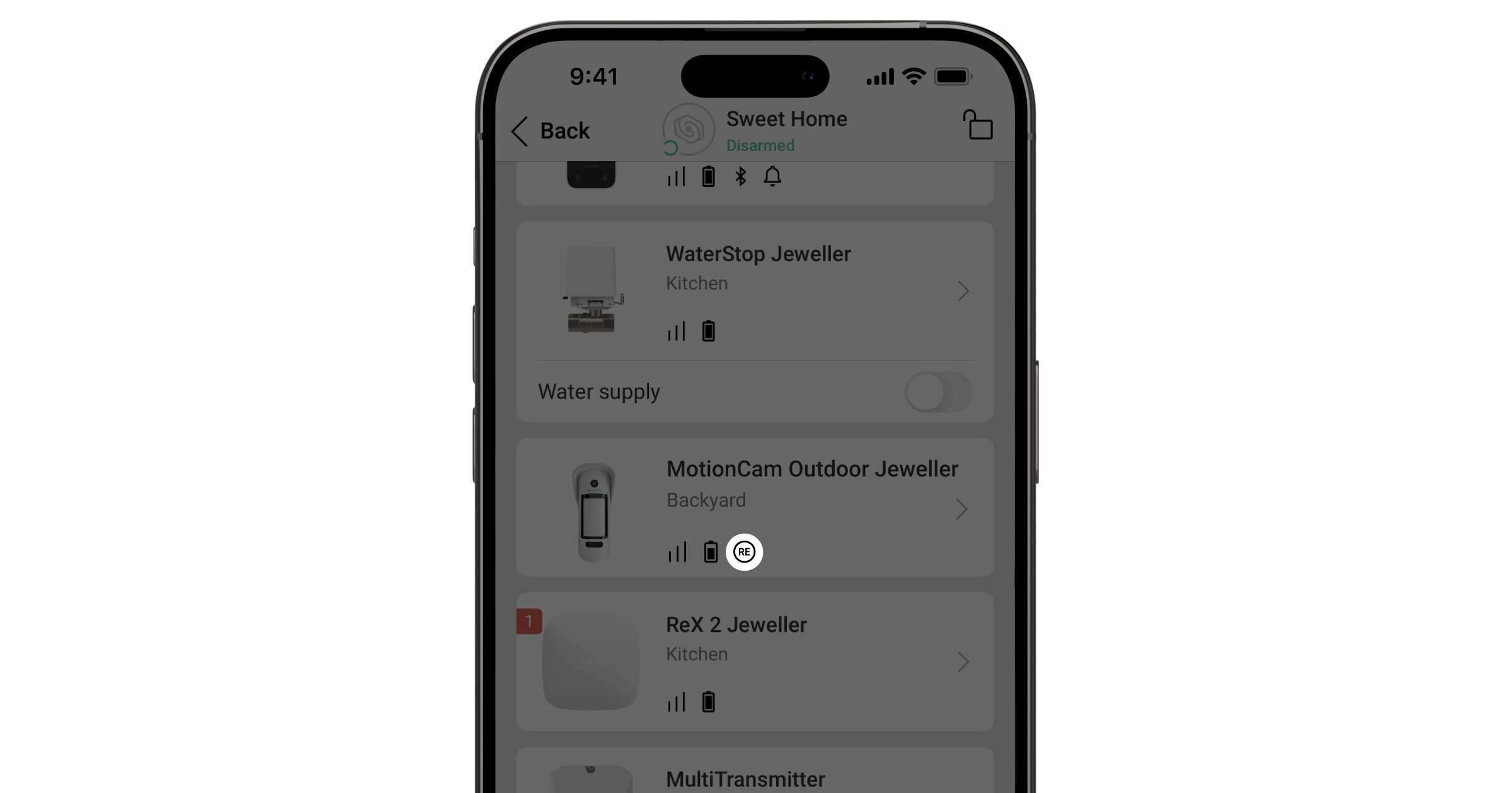
The device operates via the radio signal range extender. |
|
|
Delay when entering and/or leaving is enabled. |
|
|
The device operates in Night mode. |
|
| Masking has been detected. | |
|
The device is in signal attenuation test mode. |
|
|
The device is automatically disabled because the number of alarms has been exceeded. |
|
|
The device has been permanently deactivated. |
|
|
Tamper alarm notifications are permanently disabled. |
|
|
The device remains deactivated until the system is disarmed for the first time. |
|
|
Tamper alarm notifications are disabled until the system is disarmed for the first time. |
|
| The device has lost connection with the hub, or the hub has lost connection with the Ajax Cloud server. | |
|
The device has not been transferred to the new hub. |
States
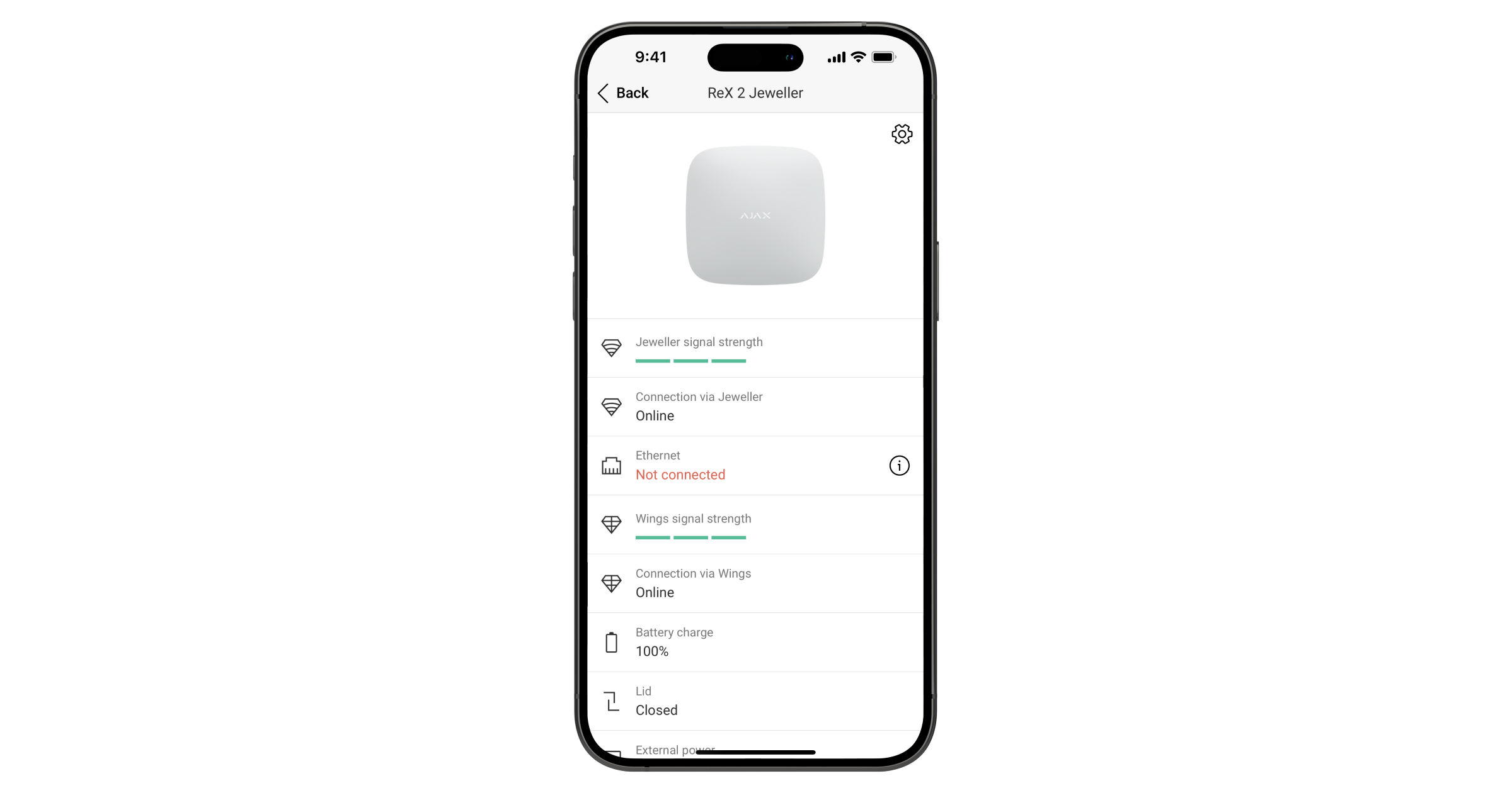
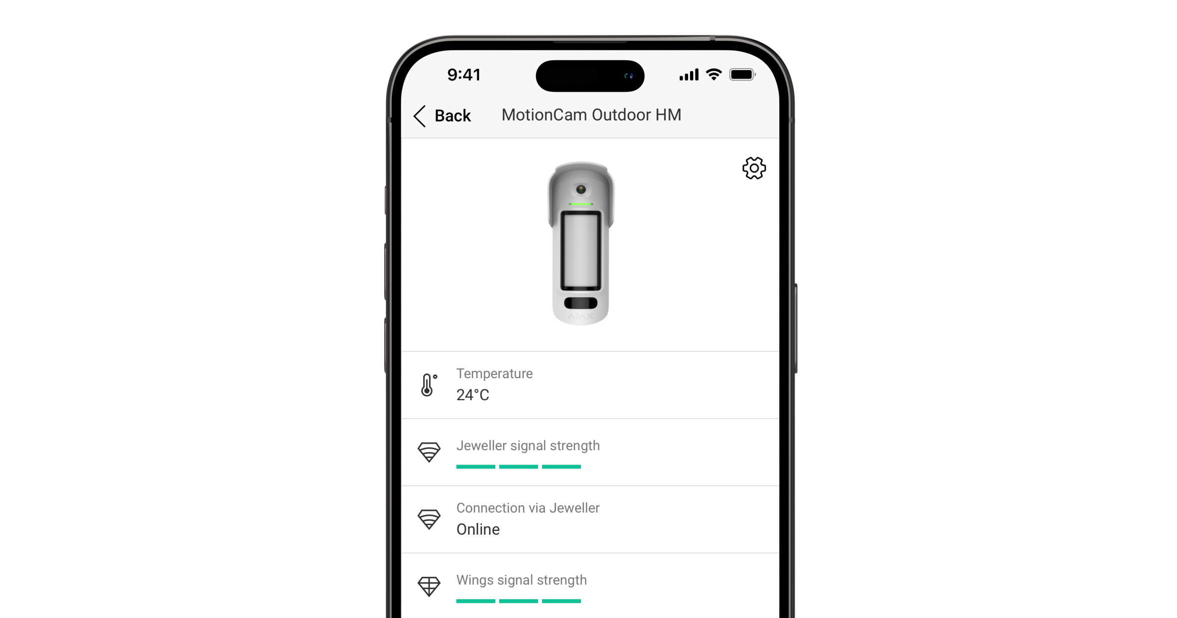
The statuses provide information about the device and its operating parameters. The statuses for the MotionCam Outdoor HighMount (PhOD) Jeweller can be found in the Ajax apps:
- Go to the" " tab under "Devices
. - Select" " "MotionCam Outdoor HighMount (PhOD)" "Jeweller from the list.
| Parameter | Meaning |
| Data Import | Displays the error that occurs when transferring data to the new hub:
|
| Malfunction |
Tapping on This field is displayed only if a malfunction is detected. |
| New firmware version available |
Tapping on This field is displayed if a new firmware version is available. |
| Temperature |
Device temperature. It is measured by the processor and varies depending on the ambient temperature. You can create a scenario based on temperature to control automation devices. MotionCam Outdoor HighMount (PhOD) Jeweller is an outdoor detector, and its temperature is not taken into account when calculating the average temperature in the room to which the detector is assigned. |
| Jeweler signal strength |
Check the signal strength between the device and the hub (or the wireless signal range extender). The recommended value is 2–3 bars. Jeweller is a protocol for transmitting events and alarms. |
| Connection via Jeweller | Connection status via the Jeweller channel between the device and the hub (or the range extender):
|
| Wings signal strength |
Wings signal strength between the device and the hub (or the range extender). The recommended value is 2–3 bars. Wings is a protocol for verifying alarms via photos and updating device firmware. |
| Connection via Wings | Connection status via the Wings channel between the device and the hub (or the range extender):
|
| Transmitter power |
Displays the selected transmitter power. The parameter appears when the" " "Max or" " "Attenuation option is selected in the" " "Signal attenuation test menu. |
| Status of the device's connection to theradio signal range extender .
This field is displayed if the device is operating via the radio signal range extender. |
|
| Battery charge | The device's battery charge level. There are two possible states:
When the batteries need to be replaced, users and the security company will receive the appropriate notifications. |
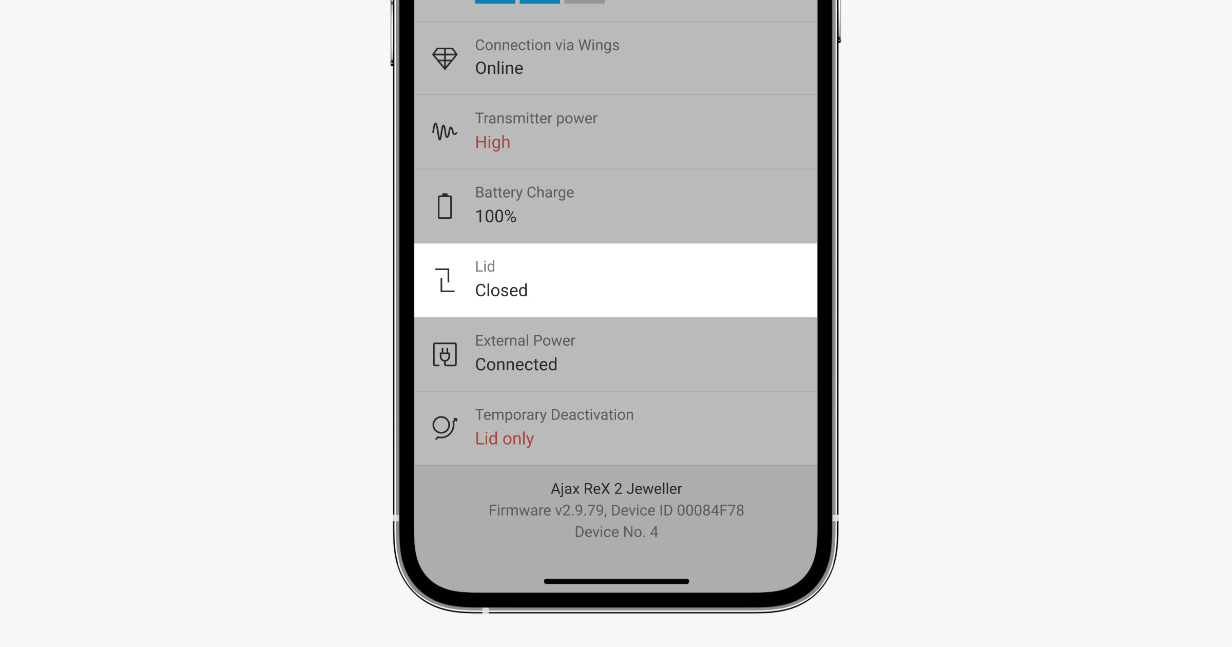
| Lid | The status of the device tamper sensors that detect detachment or opening of the device enclosure:
|
| External power | External power state:
|
| Transmitter power |
Displays the selected transmitter power. The parameter appears when the" " "Max or" " "Attenuation " option is selected in the" " "Signal attenuation test menu. |
| Sensitivity | Motion detector sensitivity level:
Select the sensitivity based on the results of the detection zone test. |
| Anti-masking | The status of the masking sensor:
|
| Always active |
When this option is enabled, the detector is constantly armed, detects motion, and triggers alarms. |
| Alert if moved | The state of the "Alert if moved setting. When this option is enabled, the built-in magnetometer detects attempts to tilt, shift, or detach the device from the surface.
|
| Permanent deactivation | The status of the device's permanent deactivation setting:
|
| One-time deactivation | Shows the status of the device's one-time deactivation setting:
|
| On-Demand Photo Access | Displayed if "Allow photos on demand is enabled in the space settings under" " >"Privacy . |
| Alarm Response | |
| Operating Mode | Shows how the detector responds to alarms:
|
| Delay upon entry |
The entry delay (alarm activation delay) is the amount of time the user has to disarm the security system after entering the premises. |
| Delay upon departure |
Delay upon leaving (arming delay) is the amount of time the user has to leave the premises after the system is armed. |
| Arm in Night Mode |
If this option is enabled, the device will enter armed mode when the system is set to" " or "Night mode." |
| Night mode delay upon entering |
Delay upon entering the : Night mode. The entry delay (alarm activation delay) is the amount of time the user has to disarm the security system after entering the premises. |
| Night mode delay when exiting |
Delay when leaving in Night Mode. The Night Mode delay when leaving (arming delay) is the amount of time the user has to leave the premises after Night Mode is enabled. |
| Night mode delay |
Delay when entering Night mode when the device is set to the Follower operating mode. This is the amount of time the user has to disable Night mode (alarm activation delay) after the Entry/Exit detector is triggered. |
| Firmware | Device firmware version. |
| Device ID | Device ID. It can also be found on the QR code on the device's casing and its packaging box. |
| Device No. | Device number. This number is transmitted to the CMS in the event of an alarm or incident. |
Settings
To change the MotionCam Outdoor HighMount (PhOD) Jeweller settings in Ajax apps:
- Go to the" " tab under "Devices
. - Select" " "MotionCam Outdoor HighMount (PhOD)" "Jeweller from the list.
- Go to Settings
. - Configure the necessary settings.
- Tap" " and then to save the new settings.
| Settings | Meaning |
| Name |
Device name. It appears in the list of hub devices, in the text of SMS messages, and in notifications in the events feed. To change the device name, tap the text field. The name can contain up to 24 Latin characters or up to 12 Cyrillic characters. |
| Room |
Selecting the virtual room to which the MotionCam Outdoor HighMount (PhOD) Jeweller is assigned. The room name appears in the text of text messages and notifications in the events feed. |
| Alarm LED Indicator | When this option is disabled, the LED indicator does not alert users to alarms or tamper events. |
| Sensitivity | Sensitivity level of the motion detector. It depends on the type of facility, the presence of potential sources of false alarms, and the specific characteristics of the protected area:
|
| Magnetic Sensor Sensitivity | Allows you to adjust the sensitivity level of the magnetic sensor. This feature is intended for situations where the specific installation conditions of the device may cause frequent false alarms indicating that the device's position has changed (e.g., when the device is installed on a metal surface):
|
| Camera activation threshold |
Allows you to adjust the threshold level for camera activation. This feature is intended for situations where the device detects a lot of movement, but these movements are filtered out as unconfirmed alarms. Each movement triggers the camera, which causes the battery to drain quickly. A high threshold reduces the number of times the camera is triggered in areas with a lot of movement and helps conserve battery life. Available threshold options:
|
| Anti-masking | When this option is enabled, the device detects masking. |
| Notify of sensor icing |
When this option is enabled, the device notifies users if the sensors are covered with ice and do not detect movement. This setting is displayed if the" " option is enabled under "Anti-masking . |
| Image resolution | The resolution of photos taken with the device's camera:
The higher the resolution, the more detailed the image is. It takes longer to transfer photos with higher resolution. The selected resolution is set for Photo by alarm, Photo by scenario, Photo on demand, Photo by schedule, and Photo by arming/disarming. |
| Photos by alarm | The number of photos taken by the device's camera:
The selected number of photos is set for "Photo by alarm and" " "Photo by scenario." |
| Alarm with Photo Verification |
The number of alarms accompanied by photos. You can choose whether the photo will be sent each time the device is triggered or specify the exact number of alarms: 1 to 10. An alarm counter with photo verification is reset when the security system is disarmed and rearmed. This setting is available if the " option is set to "Always active and the " " option is disabled. When the detector is in " mode , it will transmit a photo every time it is triggered. |
| Photos on Demand | The number of photos requested:
It is displayed if the" " feature ("Allow photos on demand ) is enabled in the space settings under" " > "Privacy . |
| Always active |
When this option is enabled, the detector is always in armed mode and detects movement. |
| Alert if moved | When this option is enabled, the device detects attempts to tilt, move, or detach it from the surface. |
| Notify users of the risk of rapid battery discharge | When this option is enabled, the user is notified when an incorrect installation affects the device’s battery life because the detector is often triggered without an actual intrusion. |
| Alert with a siren | |
| If motion is detected | When this option is enabled, sirens are activated when the device detects movement. |
| If masking is detected |
When this option is enabled, sirens are activated when the device detects masking. The parameter is displayed if the" " option under "Anti-masking is enabled. |
| If the device was moved |
When this option is enabled, the sirens are activated when the device detects attempts to tilt, shift, or detach it from the surface. This setting is displayed if the" " option under "Alert if moved is enabled. |
| Alarm Response | |
| Operating Mode | Specify how this device responds to alarms:
|
| Delay upon entry |
Delay upon entry: 5 to 255 seconds. The entry delay (alarm activation delay) is the amount of time the user has to disarm the security system after entering the premises. |
| Delay upon departure |
Delay when leaving: 5 to 255 seconds. Delay upon leaving (arming delay) is the amount of time the user has to leave the premises after the system is armed. |
| Arm in Night Mode |
When this option is enabled, the detector will enter armed mode if the system is set to" " or "Night" mode. |
| Night mode delay upon entering |
Delay when entering Night mode: 5 to 255 seconds. The night mode delay upon entry (alarm activation delay) is the amount of time the user has to disable Night mode after entering the premises. |
| Night mode delay when exiting |
Delay when leaving the" " Night mode: 5 to 255 seconds. The night mode delay upon leaving (arming delay) is the amount of time the user has to leave the premises after enabling Night mode. |
| Night mode delay |
Delay time in , Night mode: 5 to 255 seconds. This is the time the user must disable Night mode (alarm activation delay) after the Entry/Exit detector is triggered. This setting is displayed if the device is set to the" " or "Follower operating mode and the Arm in Night mode option is enabled. |
| Scenarios |
Opens the menu for creating and configuring scenarios for the device. The menu allows you to create a scenario in which the detector takes photos when specific Ajax devices are triggered or according to a schedule. |
| Firmware Update | Switches the device to firmware update mode if a new version is available. |
| Motion Detection Area |
Opens the menu for checking the motion detection area. You can take a photo to check the camera's field of view and maximum detection zone. The photo helps you adjust the detector's tilt angle and horizontal position correctly. |
| Jeweler Signal Strength Test |
Switches the device to the Jeweller signal strength test mode. The test allows you to check the signal strength between the hub (or the radio signal range extender) and the device via the wireless Jeweller data transfer protocol in order to select the optimal installation location. |
| Wings Signal Strength Test |
Switches the device to the Wings signal strength test mode. The test allows you to check the signal strength between the hub (or the wireless signal range extender) and the device using the Wings wireless data transfer protocol in order to select the optimal installation location. |
| Detection Zone Test |
Switches the device to detection zone test mode. This option allows you to test motion and masking sensors. The test helps verify whether the device is installed correctly to detect all alarms. |
| Signal Attenuation Test |
Switches the device to signal attenuation test mode. |
| User Guide | Opens the MotionCam Outdoor HighMount (PhOD) Jeweller user manual in an Ajax app. |
| Permanent deactivation |
Allows a user to disable events on the device without removing it from the system. There are three options available:
The system can also automatically deactivate devices when the set number of alarms is exceeded. |
| One-time deactivation |
Allows a user to disable the device's events until the system is disarmed for the first time. There are three options available:
|
| Delete device | Unpairs the device, disconnects it from the hub, and deletes its settings. |
Configuring the motion detection area
The"Motion Detection Area feature allows you to take a test photo to check the camera’s field of view and the sensors’ detection zones and ranges. The test photo helps you adjust the detector’s tilt angle and horizontal position. Proper installation of the device ensures efficient motion detection and prevents false alarms.
It is recommended that you check the motion detection area once the device is installed or if the installation location has changed.
The tilt angle depends on the detector's installation height. To set the correct tilt angle relative to the installation height, refer to the table below or the" " section in the "Installation manual.
If the device's tilt angle is correct, the distance from the ground at the device's installation point to the lower horizontal line of the motion detection area in the test photo should not exceed 0.5 m.
Before taking a test photo, make sure that a user with admin rights has enabled the" " and"Photo on demand features and has granted your account permission to Always take and view photos for this device in the Privacy settings. Otherwise, you will receive a message indicating that you lack the necessary permissions.
To take a test photo of the motion detection area in an Ajax app:
- Go to the" " tab under "Devices
. - Select" " "MotionCam Outdoor HighMount (PhOD)" "Jeweller from the list.
- Go to Settings
. - Go to the" " menu, then select "Motion Detection Area" and ."
- Tap Takea photo of the " ."
- The detector is installed correctly if:
- the photo shows the correct motion detection area;
the distance from the ground at the device installation point to the lower horizontal line of the motion detection area in the test photo does not exceed 0.5 m.
If not, adjust the tilt angle and horizontal position of the detector, and tap“ ” to take another photo.
- Tap Back to close the photo.
You can download the test photo showing the sectors of the sensors’ detection zones and ranges. The most recent test photo is also available in the" " > "Motion Detection Area" > menu, along with the date and time it was taken.
Configuring the "Photo on Demand" Feature
An administrator or a user with access to privacy settings can enable and configure the" " "Photos on demand feature. To do this, in an Ajax app:
- Select a space.
- Go to the" " tab inControl
. - Go to the space Settings
. - Go to the Privacy settings.
- , select the "Allow photos on demand" option .
- Select the user category:
- Users
- Installers
- Companies
- Select a specific user, a PRO, or a company. A list of cameras, DVRs, and detectors that support photo verification and have been added to the space will open.
- Select the device you want to grant access to.
- Enable the" " optionto take and view photos .
- Specify when the user can take on-demand photos: Always or When the device is armed.
- Tap" " and then to save the settings.
- Repeat steps 6–11 for any other users and devices to which you want to grant access.
After saving the privacy settings, all users who have access to the event feed will receive a notification indicating who has been granted access rights and which user granted those rights.
Configuring the "Photo by Scenario" Feature
First, you need to enable the" "feature (Photo by scenario ) in the " (Privacy ) settings. After that, you can create scenarios for taking photos when alarms are triggered by the specified devices.
Enabling the "Photo by Scenario" feature
An admin or a user with access to privacy settings can enable and configure the" " feature forphotos by scenario . To do this, in an Ajax app:
- Select a space.
- Go to the" " tab inControl
. - Go to the space Settings
. - Go to the Privacy settings.
- Enable the " option and select "Allow photos by scenarios .
- Tap" " and then to save the settings.
Creating a scenario for taking photos when an alarm is triggered on a specified device
An admin or PRO with system configuration rights can create and configure a scenario based on an alarm. To do this, in an Ajax app:
- Select a space.
- Go to the" " tab under "Devices
. - Select a detector that supports photo verification from the device list.
- Go to its Settings
. - Go to "Scenarios" and tap" " "Add scenario."
- Select the scenario type By schedule.
- Select the devices and types of alarms that will trigger photo verification.
- Specify:
- Name s of the scenario.
- Devices that trigger the scenario. Select which devices trigger the scenario (available if two or more devices are selected for this scenario):
- Any — the scenario will run if any selected device is triggered.
- All selected — the scenario will run if all selected devices are triggered.
- Maximum actuation time for all selected devices. The time frame within which all selected devices must be triggered for the scenario to run. Available only for the“ ” and “All selected options.
- Device action —only “Take photo” by default. The number of photos equals the number of“ Photos by alarm” specified in the settings.
- When the detector takes photos: Always or When armed. By default, the motion detector takes photos by scenario only when armed.
Note that only an admin can specify when the detector takes photos.
- Tap" " and "Save." The scenario will appear in the list of device scenarios.
Configuring the "Photo by Schedule" Feature
An admin or PRO with system configuration rights can create and set up a scenario based on a schedule. To do this, in an Ajax app:
- Select a space.
- Go to the" " tab under "Devices
. - Select a detector that supports photo verification from the device list.
- Go to its Settings
. - Go to Scenarios and tap the Add scenario button.
- Select the" " by schedule scenario type.
- Specify:
- Name , of the scenario.
- Device action — Take photo , by default. The number of photos equals the numberof Photos on demand , as specified in the settings.
- Execution time — the time of day when the detector takes photos according to the schedule.
- Repeat — the days of the week when the detector takes photos on a schedule.
- When the detector takes photos: Always or When armed. By default, the motion detector takes photos according to the schedule only when armed.
Note that only an admin can specify when the detector should take photos.
- Tap" " and "Save." The scenario will appear in the list of device scenarios.
Indication
The MotionCam Outdoor HighMount (PhOD) Jeweller LED indicator can light up green or red, depending on the device's status.
Indicator when the power button is pressed
| Event | Indication |
| Turning on the device. | The light turns green for about 0.5 s. |
| Turning on a device that has not been added to the hub. | The light turns green for about 0.5 seconds, flashes green 6 times, and flashes red 3 times rapidly. |
| Turning off the device. | It lights up red for about 1 second, then flashes 3 times. |
Indicator of an activated device
| Event | Indication | Note |
| The device is added to the hub. | The light turns green for about 0.5 s. | |
| The device is removed from the hub. | It flashes green six times for 2 seconds, then flashes red three times rapidly after 0.5 seconds. | |
|
The light turns green for about 0.6 s. | |
| The motion sensor detection zone test is currently running on the device. | The light stays green and turns off for 0.6 seconds when motion is detected. | Learn more |
| The detection zone test for the masking sensor is currently running on the device. | It stays lit red and turns off completely when masking is detected. When the masking is removed, it turns red again. | Learn more |
| Calibration of the masking sensor and magnetometer is currently underway. | The light turns green for 0.5 seconds and then turns off for 0.5 seconds. | Starts automatically when the device is installed on SmartBracket. |
| The battery is low. | It slowly lights up green and slowly goes out when the device is triggered. | The battery needs to be replaced. |
| The battery is completely discharged. | Flashes green continuously. | The battery needs to be replaced. |
| There is a hardware error or a sensor malfunction. | It turns red for about 1 seconds every 4 seconds. | The device requires maintenance; contact our Technical Support. |
| Calibration of the masking sensor or magnetometer has failed. | It turns red for about 1 seconds every 13 seconds. |
Make sure the device is installed correctly and that nothing is obstructing its field of view. Remove the device from the SmartBracket and reinstall it to restart the calibration. If the message appears again, contact our Technical Support. |
| Downloading a new firmware version for the device. | It flashes green twice and turns off every 3 seconds. | |
| The device firmware is being updated. | Flashes green twice every second. | The indicator remains on until the firmware update is complete. |
Malfunctions
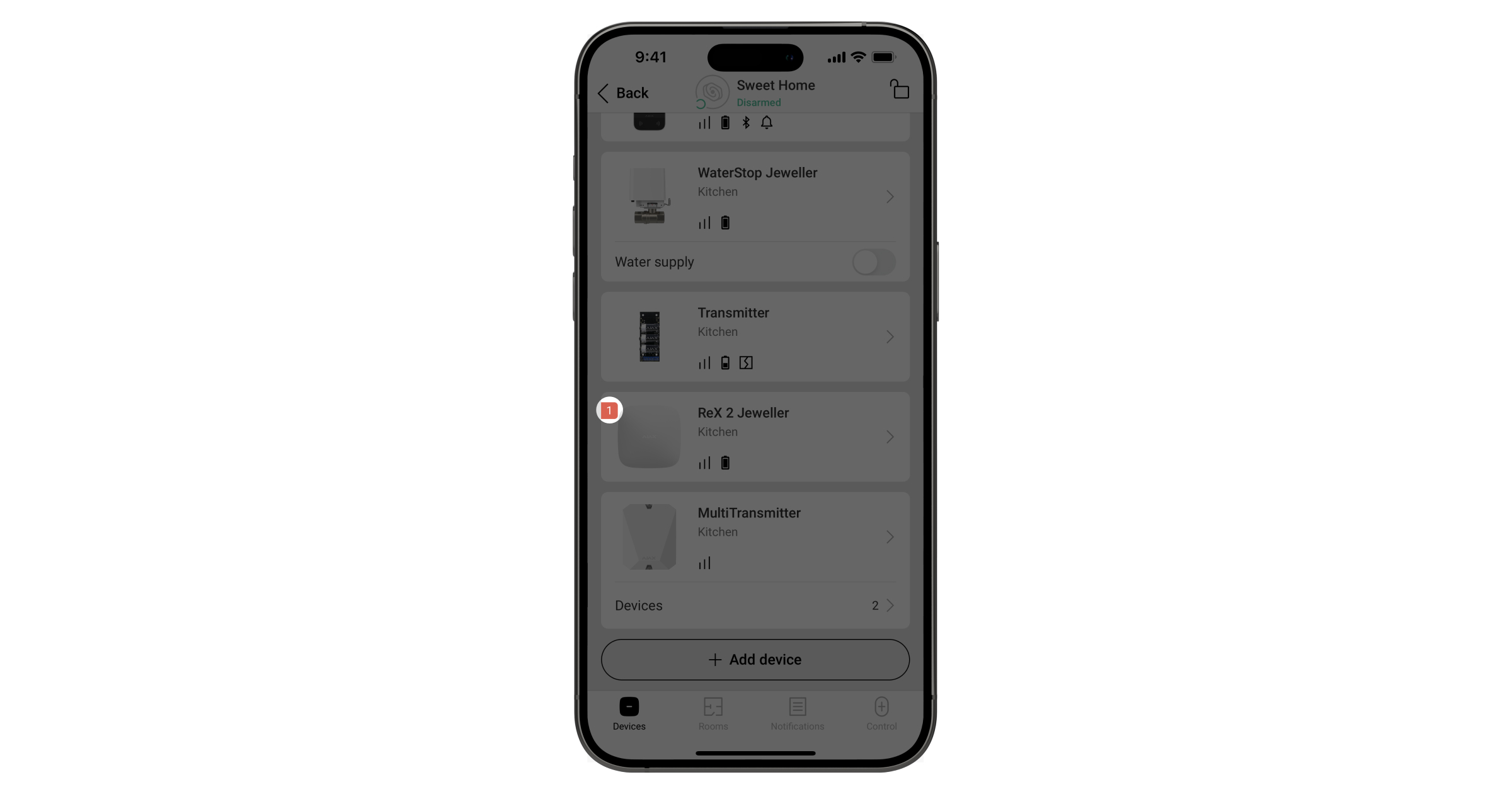
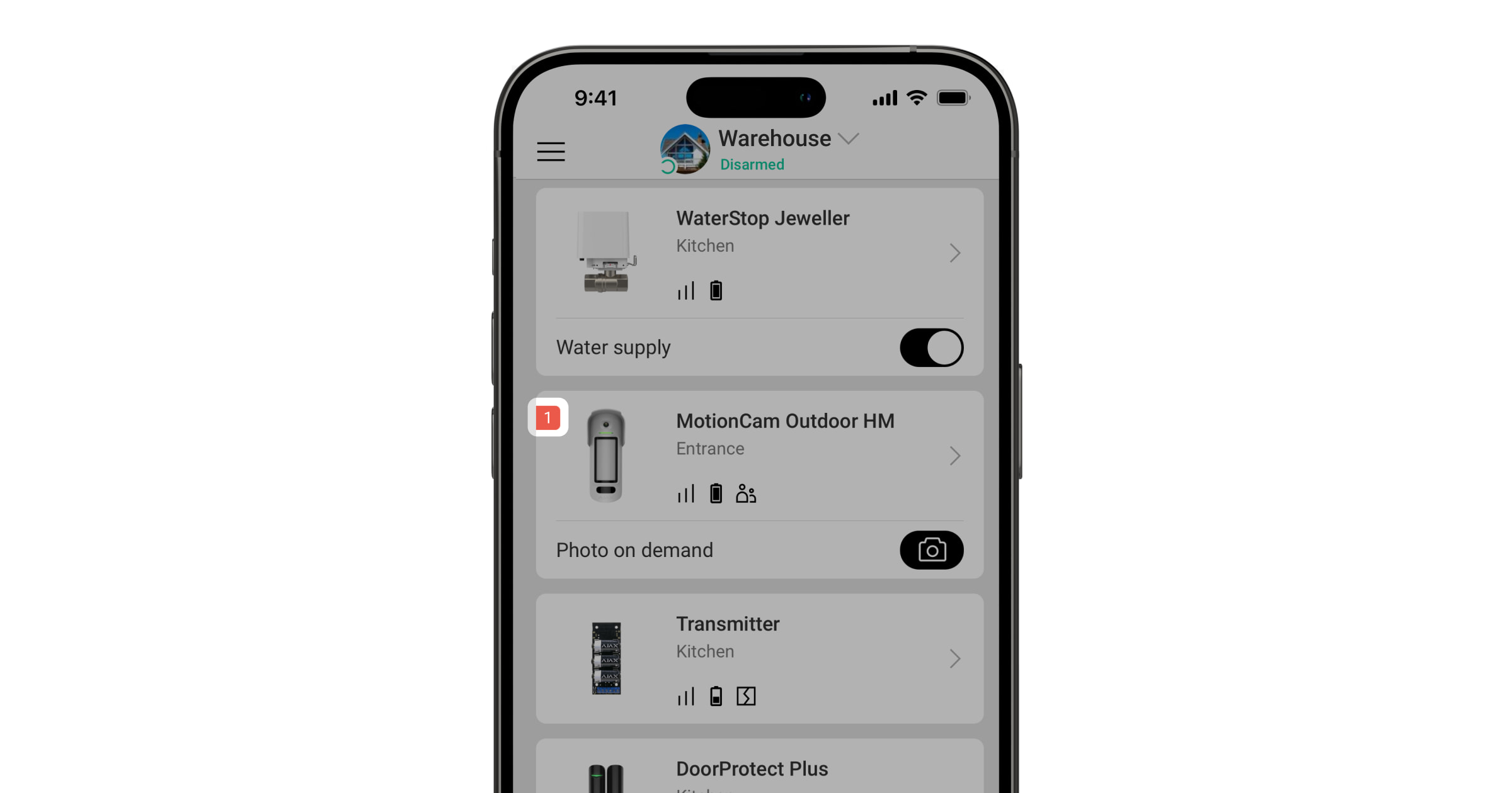
When the device detects a malfunction (for example, there is no connection via the Jeweller protocol), a malfunction counter appears in the Ajax app in the upper-left corner of the device icon.
All malfunctions can be viewed in the device' . Fields with malfunctions will be highlighted in red.
A malfunction is indicated if:
- The camera module is defective. The device detects motion but cannot take photos.
- The device temperature is outside the acceptable range.
- The device lid is open (the tamper switch has been triggered).
- The masking sensor could not be adjusted.
- Magnetometer error.
- There is no connection to the hub or the radio signal range extender via Jeweller.
- There is no connection to the hub or the radio signal range extender via Wings.
- The device's battery is low.
Maintenance
Check the device's operation regularly. The recommended frequency is once every three months. Clean the device housing of dust, cobwebs, and other contaminants as they accumulate. Use soft, dry wipes suitable for equipment maintenance.
Do not use substances containing alcohol, acetone, gasoline, or other active solvents to clean the device. Wipe the lens carefully, as scratches may reduce the detector's sensitivity.
The pre-installed batteries provide up to 3 years of battery life for the detector at a rate of 1 alarm per day with the standard Jeweller settings (the polling interval is 36 seconds). The security system will send an appropriate notification if the detector’s batteries are nearly depleted. The LED will light up and gradually fade out when the device detects any movement or if the tamper is triggered.
The MotionCam Outdoor HighMount (PhOD) Jeweller can operate for up to 2 months after a low-battery alert is received. We recommend replacing the batteries immediately upon receiving the alert. We recommend using lithium batteries, as they have a high capacity and are less affected by temperature fluctuations.
Technical Specifications
Warranty
The warranty for products manufactured by “Ajax Systems Manufacturing” Limited Liability Company is valid for 2 years after purchase.
If the device does not work properly, we recommend contacting customer support first, as most technical issues can be resolved remotely.