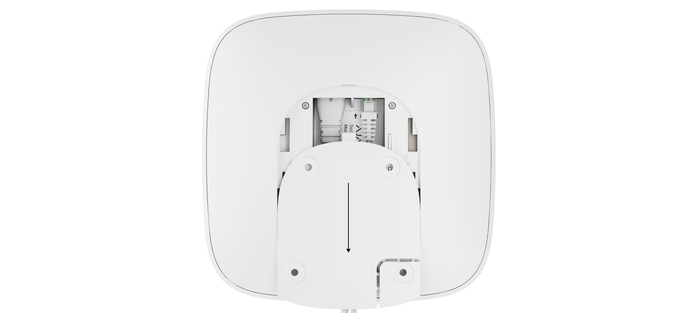
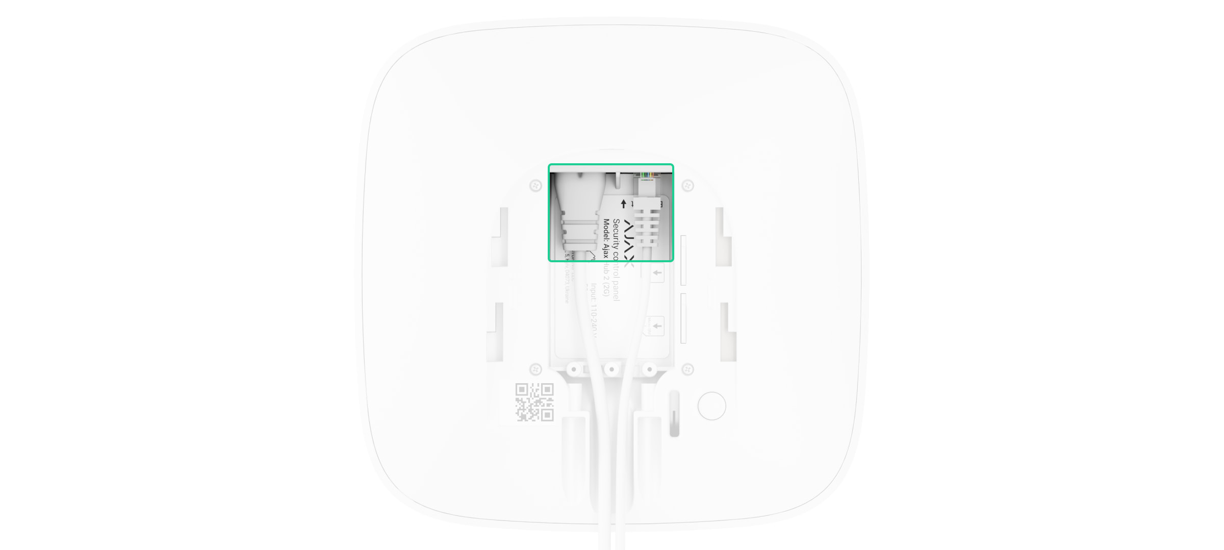
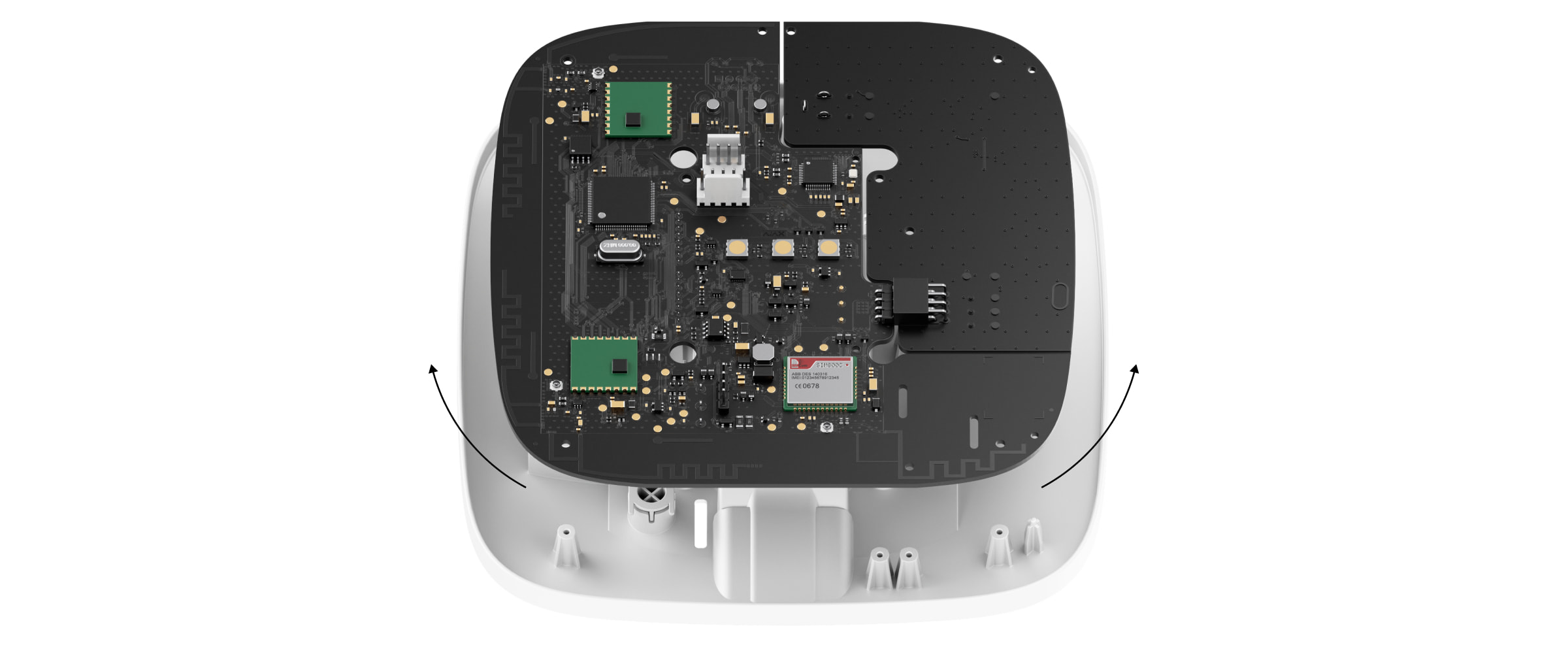
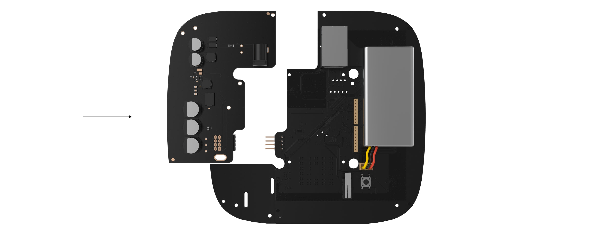
12V PSU for Hub 2/ReX 2is a power supply unit, connecting theHub 2control panels to 12 volt DC sources. This is an electronic board, replacing the standard 110/230 V power supply unit in the body of the device.
12V PSU for Hub 2/ReX 2 should be installed by a qualified electrician only.
Before installing the power supply, make sure that the device is disconnected from the mains.
When installing the 12V PSU for Hub 2/ReX 2, follow the general electrical safety rules, as well as the requirements of electrical safety regulatory acts. Never disassemble the device while it is under voltage!
Installation process:
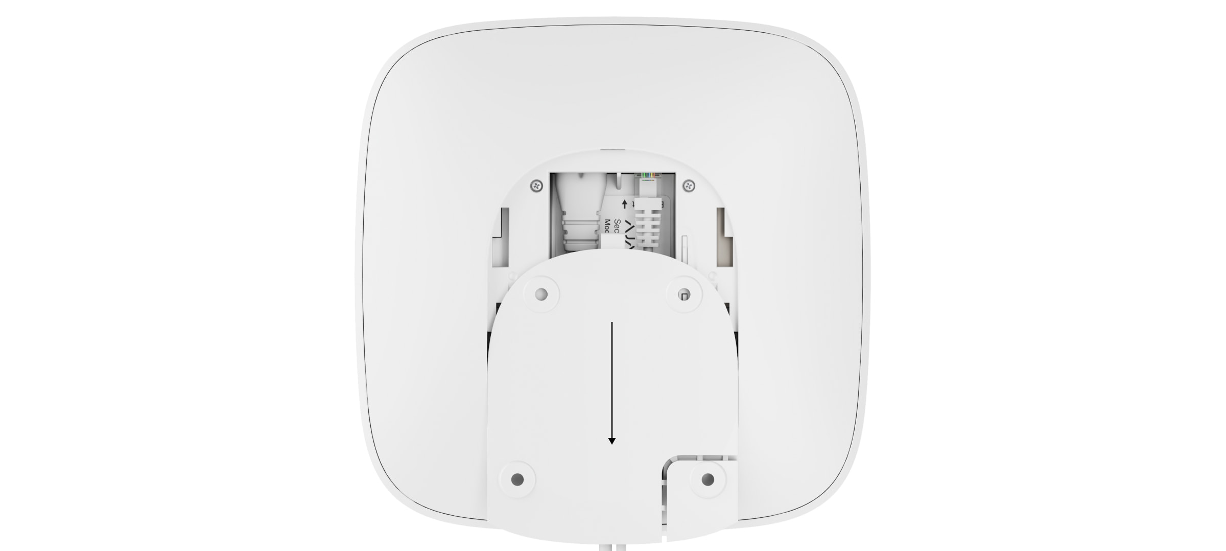
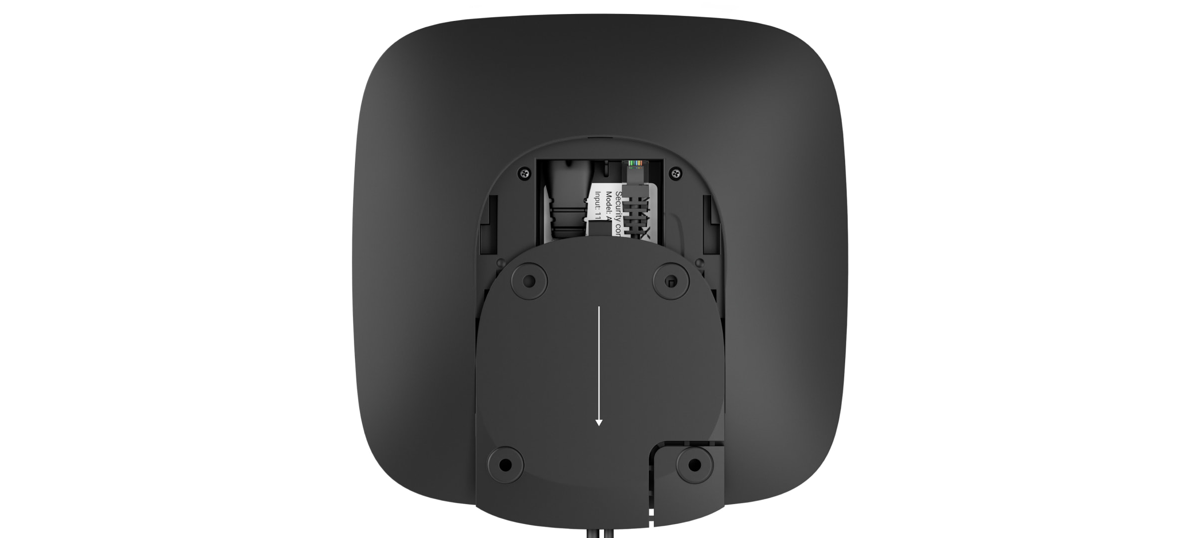
Remove the screws and take off the device from the SmartBracket mounting panel, shifting it down with force.
Switch off the device holding the power button for 2 seconds.
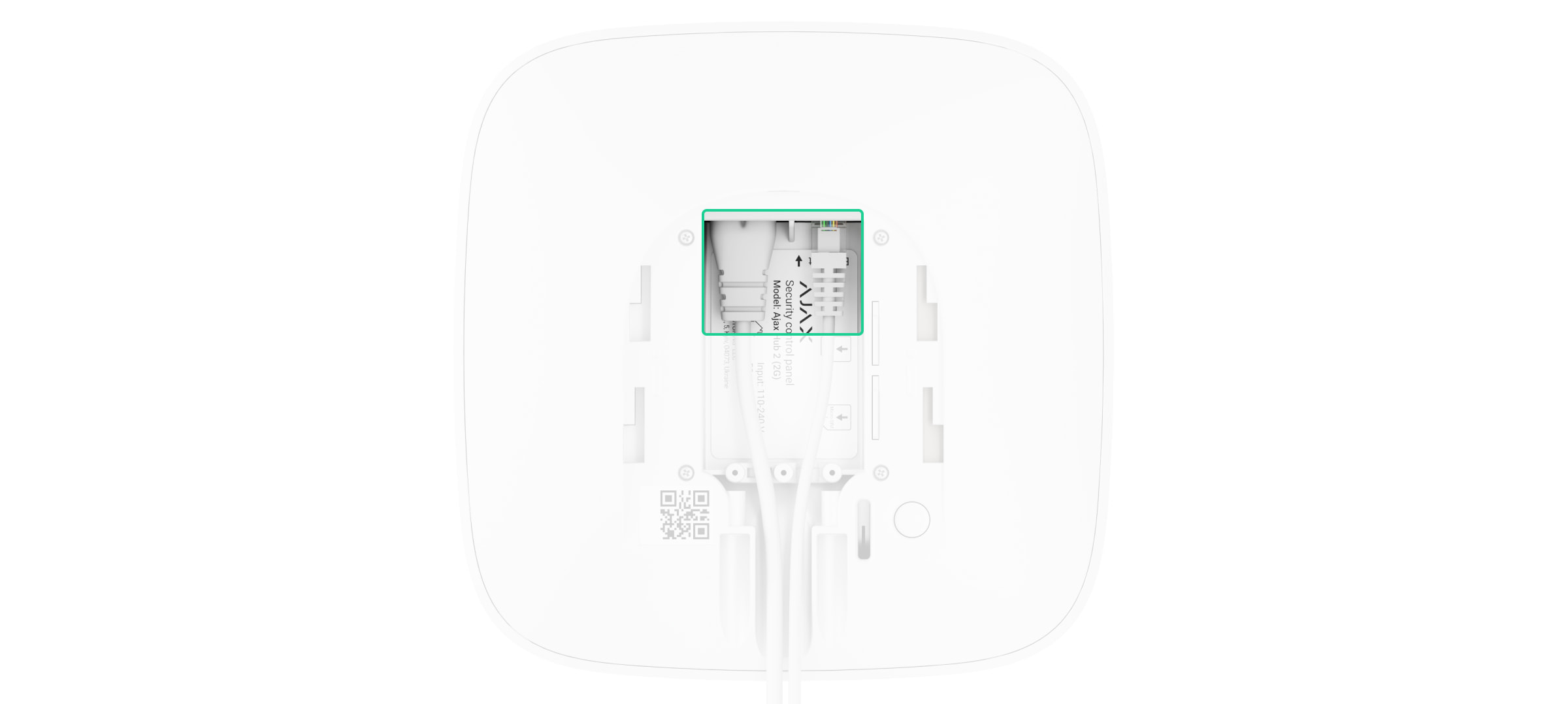
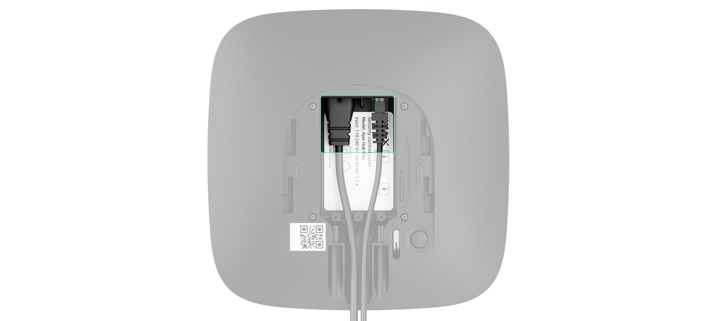
Disconnect power and Ethernet cables.
Wait 5 minutes for the capacitors to discharge.
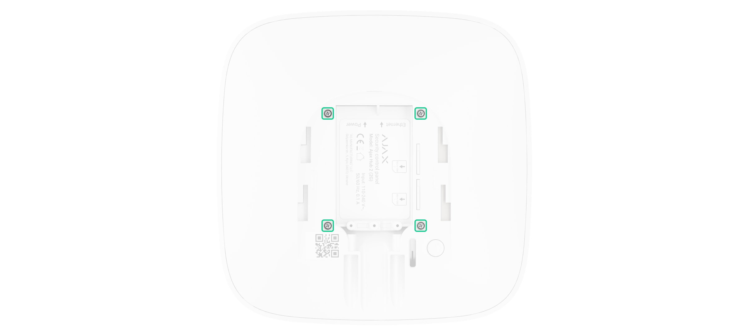
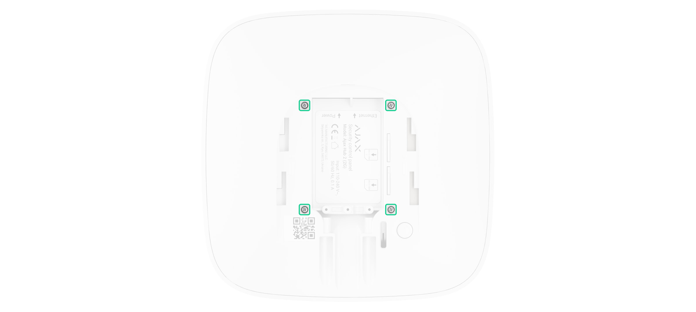
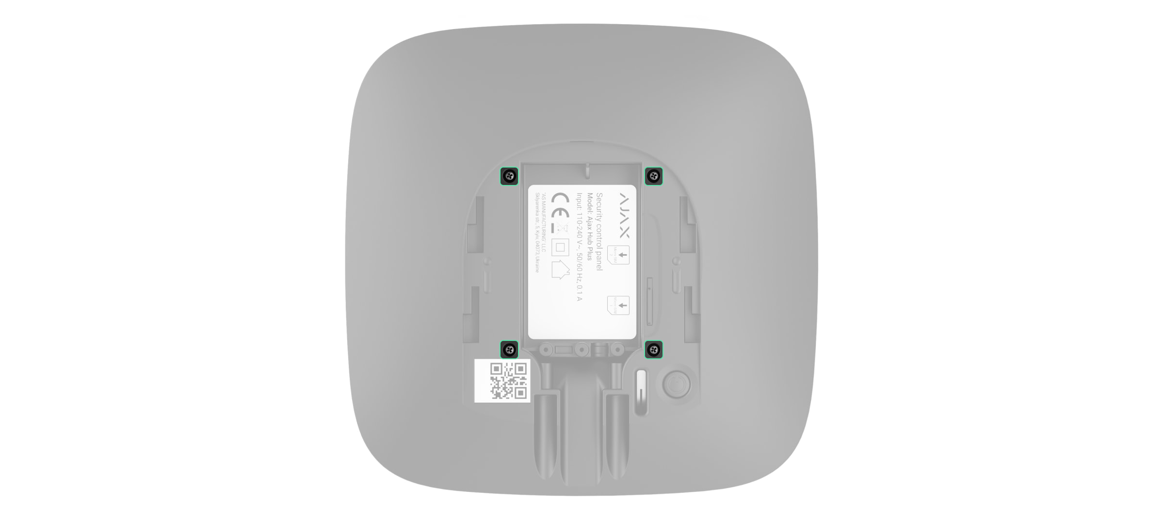
Remove four screws of the back lid and take it off.
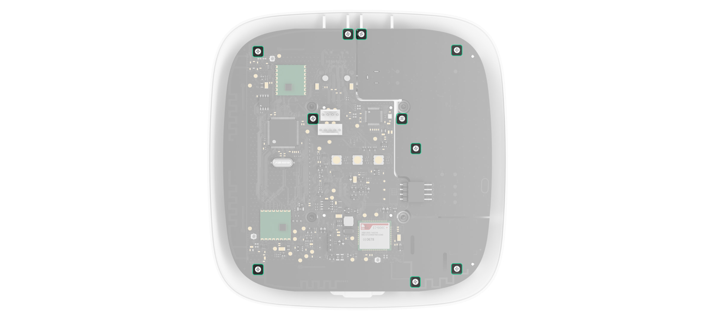
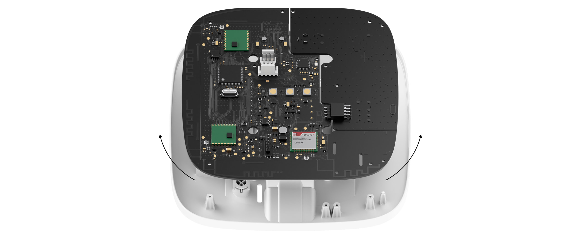
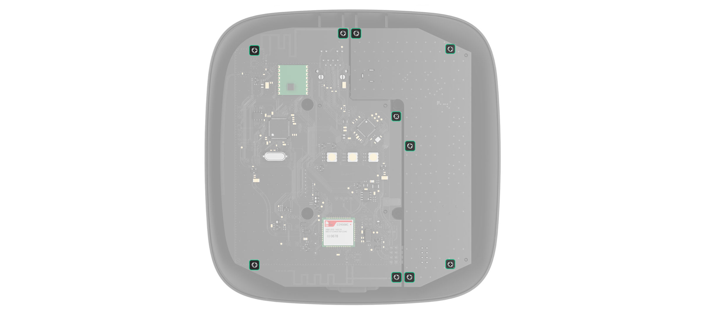
Remove the screws attaching the boards to the device body.
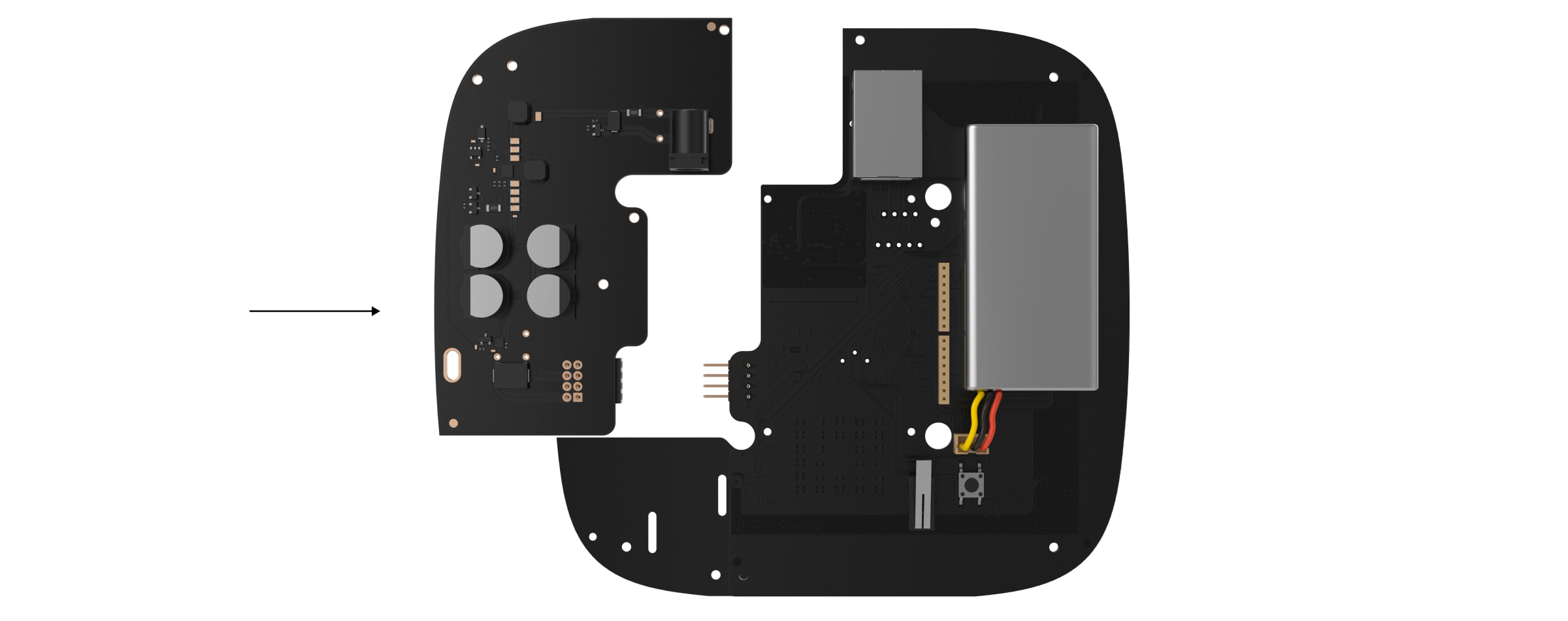
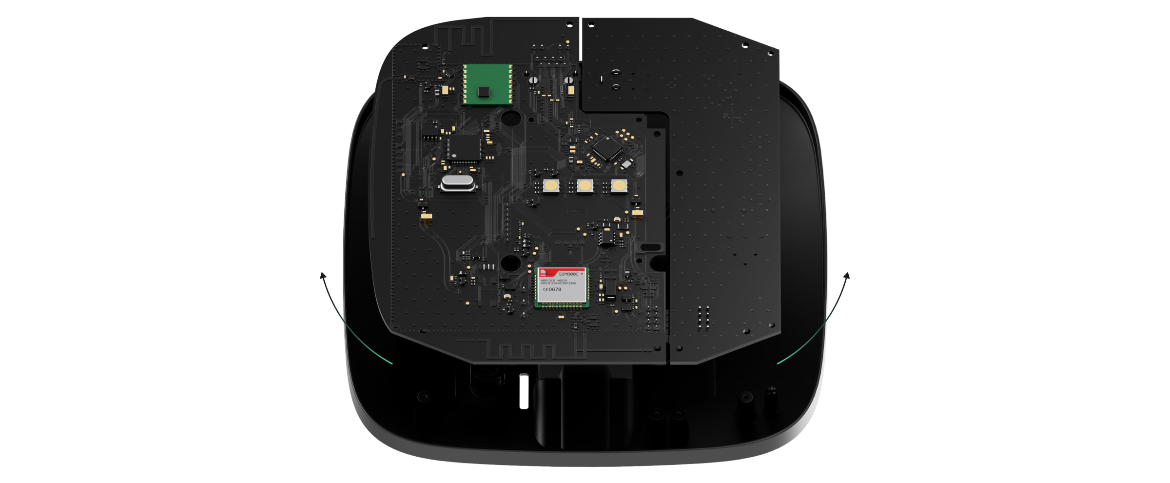
Carefully remove both boards, keeping them in the same plane and not disconnecting them. There is a connector between boards: do not break it.
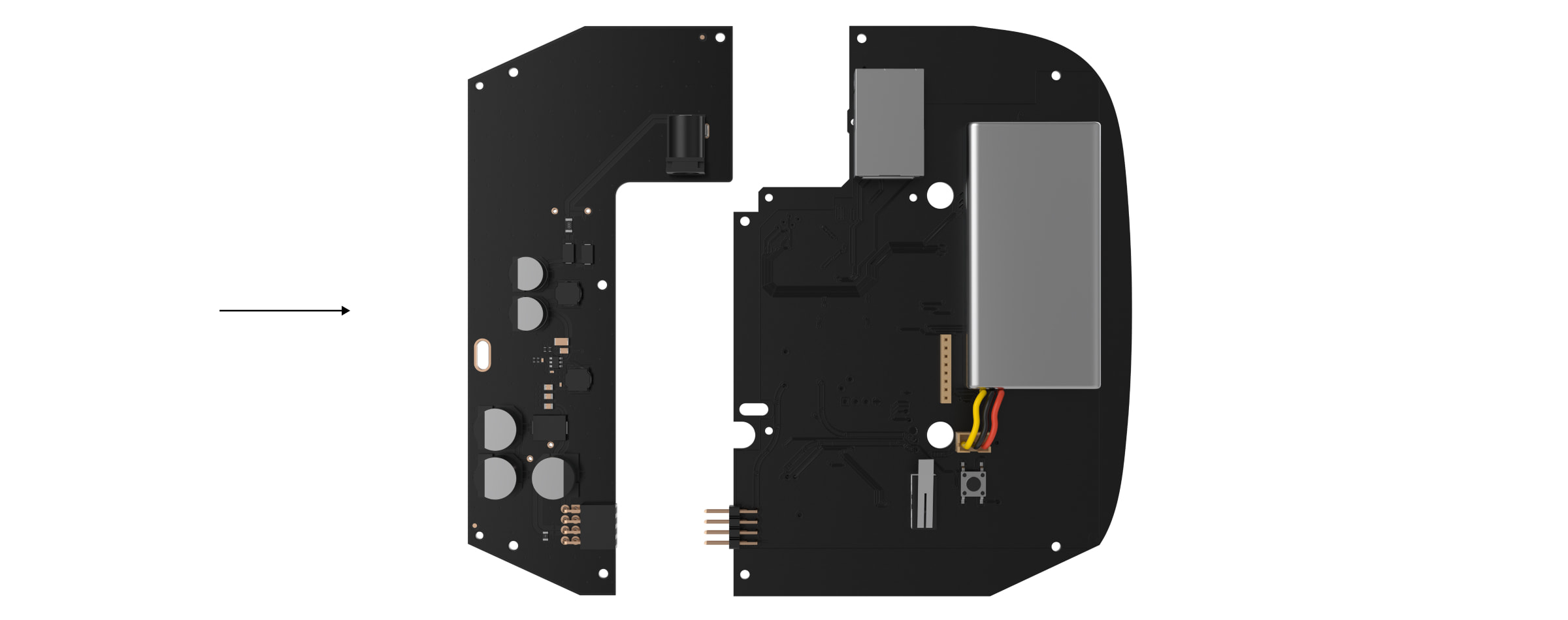
Disconnect the power supply unit (smaller board) from the mainboard.
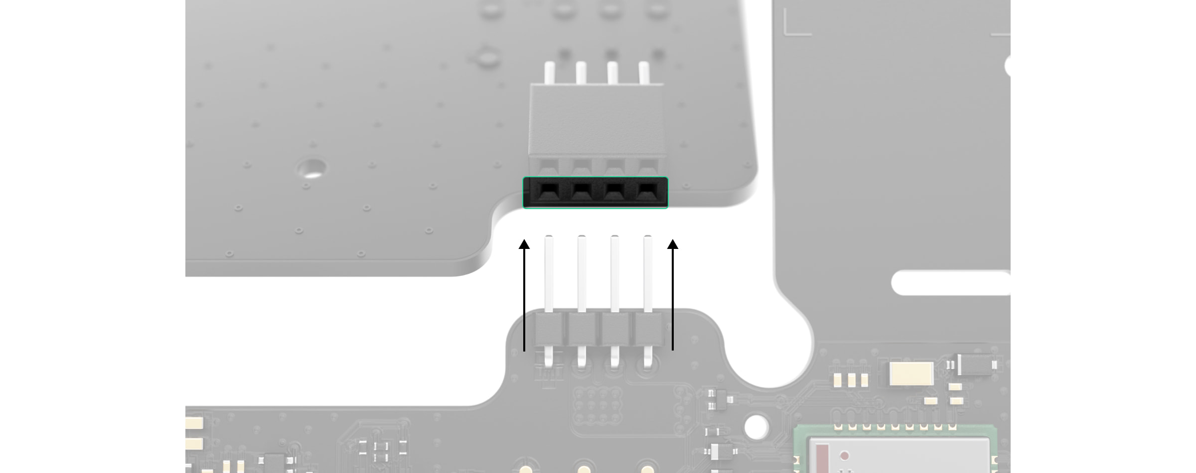
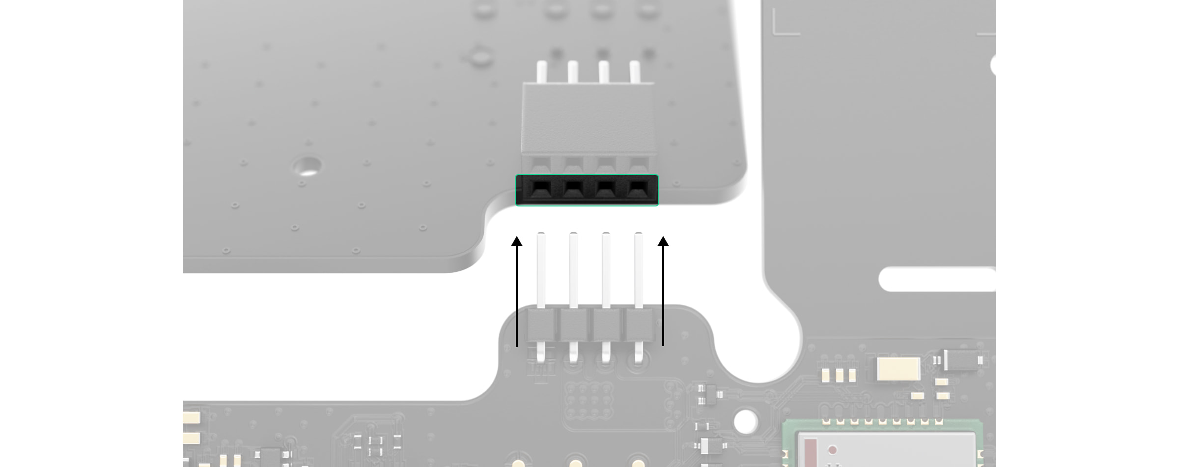
Connect 12V PSU for Hub 2/ReX 2 to the mainboard using the eight-pin connector between them. Do not warp or bend the antennas while replacing the board: this can cause the device to malfunction.
Please note: the board contacts should be plugged in the bottom row of the connector (closest to the board). When connected correctly, the boards are on the same level.
Reassemble the boards and the device body than tighten the screws.
Check that the battery and its cables are not clamped. When installed properly, the boards stand firmly on all guides and do not stagger. Holding the boards together with the back lid, turn the device over. The SIM card slot, power, and Ethernet sockets should match accurately and fit the corresponding sockets, and the power button should not be stuck. Change the information about input voltage on the device body to avoid incorrect power connections in the future. Use the special bundled sticker with the instruction.
Connect the power (and Ethernet cable) to the appropriate sockets.
Switch on the 12 V power source.
Do not connect the power cable with a voltage that exceeds the acceptable input voltage.
Switch on the device by holding the power button for 2 seconds.
Close and fix the SmartBracket mounting panel.
Switch on the device, wait until loading, and check the external power status in the Ajax app. If there is no power, and you are using a terminal adapter, check the polarity of the connected wires. If there is no power even after reconnecting, please contact the Support Service.
Maintenance
The device does not require technical maintenance.
Ajax ExternalAntenna Jeweller LTE/radio up to 2690MHz melnā
SKU: 367313476
€20,19
Vienības cena
Produkta specifikācija
Galvenās īpašības: 2G/3G/LTE, Jeweller, Wings Darbības frekvences: 698–960 MHz, 1 710–2 690 MHz Savienotājs: SMA Sabotāžas aizsardzība: ārējās antenas bojājuma noteikšana (Ajax sistēma spēj noteikt antenas bojājumu un paziņot lietotājiem un apsardzes uzņēmumam) Uzstādīšana: antena tiek pievienota pie centrāles sakaru kanāliem un izvadīta ārpusē caur centrāles korpusa atverēm; stiprināšana ar iepriekš uzklātu abpusēju līmlenti Izmēri: 115,6 × 21,7 × 5,8 mm Kabeļa garums: 3 000 mm Svars: 41 g Darbības temperatūra: –40 °C līdz +85 °C Darbības mitrums: līdz 95 % Krāsa: Melna Komplektācija: Ārējā antena, Ātrās uzstādīšanas rokasgrāmata
Ajax Transmitter Integrācijas modulis, vadu devēju pieslēgšana pie AJAX sistēmas (1 zona), nodrošina barošanu.
SKU: 367307582
€45,74€59,99
Vienības cena
Transmitter User manual
Updated
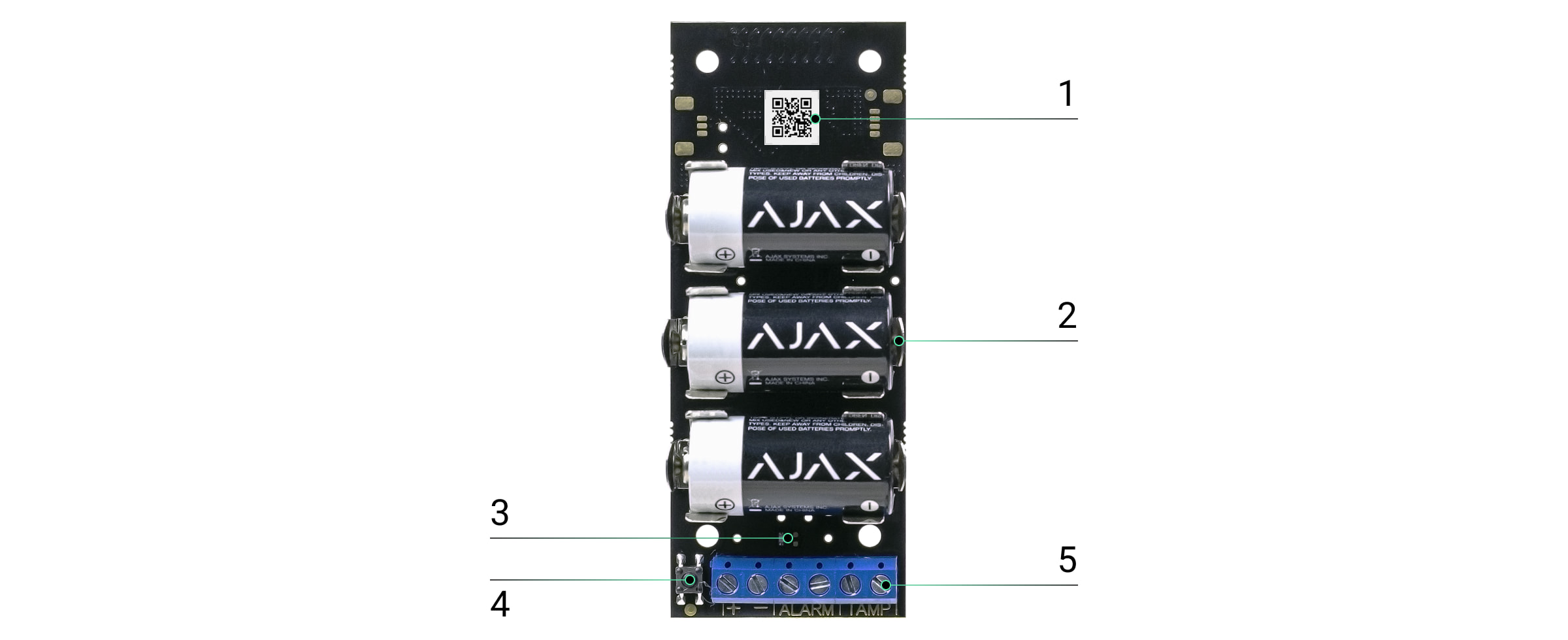
Transmitteris a module for connecting third-party detectors to Ajax security system. It transmits alarms and notifies when the tamper of the third-party detector triggers. The module is equipped with its own accelerometer, which protects it from dismounting. It runs on batteries and can supply power to the connected detector.
Transmitter operates within the Ajax security system, by connecting via the protectedJewellerprotocol to thehub. It is not intended to use the device in third-party systems.
Terminals for detector power supply, alarm, and tamper signals.
Operation procedure
Transmitter is designed to connect third-party wired sensors and devices to the Ajax security system. The integration module receives information about alarms and tamper activation through the wires connected to the clamps.
Transmitter can be used to connect panic and auxiliary request buttons, indoor and outdoor motion detectors, as well as opening, vibration, breaking, fire, gas, leakage, and others wired detectors.
Also, you can set up KeyArm Zone that allows switching system arming modes with a third-party device connected to Transmitter. KeyArm allows you to arm/disarm the system, individual groups, or manageNight Mode.
The KeyArm feature is supported by all hubs (except Hub model) with OS Malevich 2.17 and higher.
The type of alarm is indicated in the settings of Transmitter. The text of notifications about alarms and events of the connected device, as well as event codes transmitted to the central monitoring panel of the security company (CMS) depend on the selected type.
Event types of wired devices
Type
Icon
Meaning
Intrusion
Alarm when motion, or opening, or other detectors trigger.
Fire
Alarm when fire detectors trigger.
Auxiliary alarm
Alarm when pressing auxiliary request button.
Panic button
Alarm when pressing the panic button.
Gas alarm
Alarm when gas concentration is exceeded.
Malfunction
Notification of the connected device malfunction.
Transmitter should be connected to Hub Plus, Hub 2 (2G), Hub 2 (4G), Hub 2 Plus, Superior Hub Hybrid (2G) or Superior Hub Hybrid (4G) with the OS Malevich 2.13.0 firmware version and higher.
Leakage
Alarm when water leakage detectors trigger.
Glass break
Alarm when the glass break sensor is triggered.
This event type operates only inPulseoperating mode.
High temperature
Alarm when the upper temperature limit is exceeded.
Low temperature
Alarm when the lower temperature limit is exceeded.
Masking
Alarm when the device masking is detected.
Duress code (opening)
Alarm when the duress code is entered.
This event type operates only inPulseoperating mode.
Vibration (seismic sensor)
Alarm when the seismic sensor is triggered.
This event type operates only inPulseoperating mode.
Custom
The type of event that is configured by the user. It is not sent to the security company monitoring station.
Transmitter should be connected to Hub Plus, Hub 2 (2G), Hub 2 (4G), Hub 2 Plus, Superior Hub Hybrid (2G) or Superior Hub Hybrid (4G) with the OS Malevich 2.13.0 firmware version and higher.
Transmitter has 2 pairs of wired zones: alarm and tamper.
A separate pair of terminals ensures power supply to the external detector from the module batteries with 3.3 V.
Connecting to the hub
The hub and the device operating at different radio frequencies are incompatible. The radio-frequency range of the device may vary by region. We recommend purchasing and using Ajax devices in the same region. You can check the range of operating radio frequencies with thetechnical support service.
Before starting connection
Following the hub instruction recommendations, install theAjax applicationon your smartphone. Create an account, add the hub to the application, and create at least one room.
Go to the Ajax application.
Switch on the hub and check the internet connection (via Ethernet cable and/or GSM network).
Ensure that the hub is disarmed and does not start updates by checking its status in the mobile application.
Only users with administrative privileges can add the device to the hub
How to connect Transmitter to the hub
Select the Add Device option in the Ajax application.
Name the device, scan or enter manually theQR code(located on the body and packaging), and select the location room.
Select Add — the countdown will begin.
Switch on the device (by pressing on/off button for 3 seconds).
For the detection and interfacing to occur, the device should be located within the coverage area of the wireless network of the hub (at a single protected object).
Request for connection to the hub is transmitted for a short time at the time of switching on the device.
If the connection to the Ajax hub failed, Transmitter will switch off after 6 seconds. You may repeat the connection attempt then.
Transmitter connected to the hub will appear in the list of devices of the hub in the application. Update of device statuses in the list depends on the device inquiry time set in the hub settings, with the default value – 36 seconds.
Icons
The icons display some of theTransmitter Jewellerstates. To access them:
Alarm when the upper temperature limit is exceeded.
Type of eventLow temperatureis selected.
Alarm when the lower temperature limit is exceeded.
Type of eventMaskingis selected.
Masking alarm.
Type of eventDuress code(opening) is selected.
Alarm caused by the system disarming using the duress code device.
Type of eventVibration(seismic sensor) is selected.
Vibration (seismic) alarm.
States
The states screen contains information about the device and its current parameters. The statuses of Transmitter and the device connected to it can be found in the Ajax app:
Go to theDevicestab.
SelectTransmitterfrom the list.
Parameter
Meaning
Data import
Displays the error when transferring data to the new hub:
Failed— the device has not been transferred to the new hub.
(displayed when the detector is in bistable mode only)
Displays the status of the connected detector alarm zone. Two statuses are available:
OK— the state of the connected detector contacts is normal.
Alert— the connected detector contacts are in alarm mode (closed if the type of contacts is normally open (NO); open if the type of contacts is normally closed (NC).
Alert if Moved
It turns on the built-in accelerometer, detecting device movement.
Always Active
When this option is enabled, the integration module is constantly armed and notifies about the connected detector alarms.
When the function is enabled, the sirens connected to the system notify about the triggering of the opening detectors integrated with the help of Transmitter, while the system is disarmed.
Shows the status of the device permanent deactivation function:
No— the device operates normally and transmits all events.
Lid only— the hub administrator has disabled notifications about triggering on the device body.
Entirely— the device is completely excluded from the system operation by the hub administrator. The device does not follow system commands and does not report alarms or other events.
By number of alarms— the device is automatically disabled by the system when the number of alarms is exceeded (specified in the settings for Devices Auto Deactivation). The feature is configured in the Ajax PRO app.
By timer— the device is automatically disabled by the system when the recovery timer expires (specified in the settings for Devices Auto Deactivation). The feature is configured in the Ajax PRO app.
Alarm Reaction
Operating Mode
Shows how the detector reacts to alarms:
Instant Alarm— the armed detector immediately reacts to a threat and raises the alarm.
Entry/Exit— when a delay is set, the armed device starts the countdown and doesn’t raise the alarm even if triggered until the countdown ends.
Follower— the detector inherits the delays from Entry/Exit detectors. However, when the Follower is triggered individually, it immediately raises the alarm.
Delay When Entering, s
Entry delay (alarm activation delay) is the time you have to disarm the security system after entering the room.
The time of Delay When Entering in the Night mode. Delay when entering (alarm activation delay) is the time you have to disarm the security system after entering the premises.
The time of Delay When Leaving in the Night mode. Delay when leaving (alarm activation delay) is the time you have to exit the premises after the security system is armed.
To change the Transmitter settings in the Ajax app:
Go to theDevicestab.
SelectTransmitterfrom the list.
Go toSettingsby clicking on the.
Set the required parameters.
ClickBackto save the new settings.
Setting
Meaning
Name
Detector name that can be changed. The name is displayed in the text of SMS and notifications in the event feed.
The name can contain up to 12 Cyrillic characters or up to 24 Latin characters.
Room
Selecting the virtual room to which Transmitter is assigned. The name of the room is displayed in the text of SMS and notifications in the event feed.
Power Supply for Connected Detectors
3.3 V power-on for a third-party wired detector:
Always enabled— use if problems are observed in the “Disabled if hub is not armed” power mode of the detector. If the security system is armed in pulse mode, signals on the ALARM terminal are processed no more than once every three minutes and always processed in the bistable mode.
Disabled if disarmed— the module powers off the external detector if disarmed and does not process signals from the ALARM terminal. Once the detector is armed, the power supply resumes, but the detector alarms are ignored for the first 8 seconds.
Always Disabled— Transmitter does not use energy to power a third-party detector. Signals from the ALARM terminal are processed in both pulse and bistable modes.
If the Always Active mode is enabled, the third-party detector power supply is on in the Always Active or Disabled if not Armed modes only, regardless of the security system status.
External Detector Contact Status
Selection of the external detector normal status:
Normally open (NO).
Normally closed (NC).
External Detector Type
Selection of the external detector type:
Bistable.
Pulse.
Sensor Mode
Selecting the sensor mode of the connected device:
Notify of Alarms.
Switch Arming Modes.
Type of event
Selecting an event type for the connected detector or device. Refer to theEvent types of wired devicessection for more information.
The texts of notifications in the event feed and SMS, as well as the code transmitted to the security company monitoring station, depend on the selected type of event.
This setting is available ifNotify of Alarmsoption is selected for theSensor Modesetting.
Arm Switch Settings
Configuring the arm switch if theSwitch Arming Modesoption is selected for theSensor Modesetting:
selecting armingPreset Action.
selectingSecurity Objectsto be controlled by KeyArm.
configuring theLock arm switch if lid is openfeature.
configuring theNotify of attempts to use arm switch when it’s lockedfeature (available for hubs with OS Malevich 2.19 or higher when theLock arm switch if lid is openfeature is enabled).
Enable theNotify of attempts to use arm switch when it’s lockedfeature to receive notifications for every attempt to switch arming mode with a locked arm switch. When locked, it cannot switch modes.
Instant Alarm— the armed detector immediately reacts to a threat and raises the alarm.
Entry/Exit— when a delay is set, the armed device starts the countdown and doesn’t raise the alarm even if triggered until the countdown ends.
Follower— the detector inherits the delays from Entry/Exit detectors. However, when the Follower is triggered individually, it immediately raises the alarm.
Delay When Entering, s
Selecting delay time when entering. Delay when entering (alarm activation delay) is the time you have to disarm the security system after entering the room.
Selecting the delay time when exiting. Delay when exiting (alarm activation delay) is the time you have to exit the room after arming the security system.
If enabled, the detector connected to the integration module will switch to the armed mode when using the Night mode.
Night mode Delay When Entering, s
The time of Delay When Entering in the Night mode. Delay when entering (alarm activation delay) is the time you have to disarm the security system after entering the premises.
The time of Delay When Leaving in the Night mode. Delay when leaving (alarm activation delay) is the time you have to exit the premises after the security system is armed.
Allows the user to disable events of the device until the first event of disarming the system.
Three options are available:
No— the device operates in the normal mode and transmits all events.
Entirely— the device is completely excluded from the system operation until the first event of disarming the system. The device does not execute system commands and does not report alarms or other events.
Lid only— notifications on the device tamper triggering are disabled while the armed mode is active.
Disconnects the device from the hub and deletes its settings.
How to set Chime
Chime is a sound signal that indicates the triggering of the opening detectors when the system is disarmed. The feature is used, for example, in stores, to notify employees that someone has entered the building.
Notifications are configured in two stages: setting up opening detectors and setting up sirens.
Before setting up the Chime feature, make sure that a wired opening detector is connected to Transmitter and the following options have been configured in the detector settings in the Ajax app:
Detector power supply
External Detector Contact Status
External Detector Type
Type of event
Tamper status
Go to theDevicesmenu.
SelectTransmitter.
Go to its settings by clicking the gear iconin the upper right corner.
Go to theChime Settingsmenu.
Select siren notification for the eventIf external contact is open.
Select the chime sound: 1 to 4 beeps. Once selected, the Ajax app will play the sound.
The LED lights up when the ON button is briefly pressed.
Registration failed
The LED blinks for 4 seconds with an interval of 1 second, then blinks 3 times rapidly (and automatically switches OFF).
The Module is deleted from the list of hub devices
The LED blinks for 1 minute with an interval of 1 second, then blinks 3 times rapidly (and automatically switches OFF).
The Module has received alarm/tamper signal
The LED lights up for 1 second.
Batteries are discharged
Smoothly lights up and goes out when the detector or tamper is activated.
Performance testing
The Ajax system allows conducting tests for checking the functionality of connected devices.
The tests do not start straight away, but within a period of 36 seconds when using the standard settings. The test time start depends on the settings of the detector scanning period (the paragraph onJewellersettings in hub settings).
Transmitter location determines its remoteness from the hub and presence of any obstacles between the devices hindering the radio signal transmission: walls, inserted floors, large-size objects located within the room.
Check the signal strength level at the installation location
If the signal level is one division, we cannot guarantee stable operation of the security system. Take possible measures to improve the quality of the signal. At least, move the device with an integration module — even a 20 cm shift can significantly improve the signal strength.
Transmitter should be installed inside the wired detector case. The module requires a space with the following minimum dimensions: 110 × 41 × 24 mm. If the installation of Transmitter within the detector case is impossible, then any available radiotransparent case could be used.
Connect Transmitter to the detector through the NC/NO contacts (choose the relevant setting in the app) and COM.
The maximum cable length for connecting the sensor is 130 m (24 AWGtwisted pair). The value may vary when using different type of cable.
The function of the terminals of Transmitter
“+ —”— power terminals of the connected wired device, the output voltage is 3.3 V⎓.
ALARM— alarm terminals of the device.
TAMP— terminals of the device tamper.
Do not connect a third-party power supply unit to the power terminals. This may damage the device
Secure Transmitter in the casing. Plastic bars are included in the installation kit. It is recommended to install Transmitter on them.
Do not install Transmitter:
Near metal objects and mirrors (they can shield the radio signal and lead to its attenuation).
Closer than 1 meter to a hub.
Maintenance and Battery Replacement
The device does not require maintenance when mounted in the housing of a wired sensor.
Warranty for the Limited Liability Company “Ajax Systems Manufacturing” products is valid for 2 years after the purchase and does not apply to the pre-installed battery.
If the device does not work correctly, you should first contact the support service — in half of the cases, technical issues can be solved remotely!
Ajax 6V Barošanas bloks priekš Hub 2/Hub 2 Plus/ReX 2
SKU: 367304808
€23,51€29,97
Vienības cena
6V PSU (type A) user manual
Updated
6V PSU (type A)is an alternative power supply unit to connect an Ajax hub or range extender to 6 V⎓ sources. This is an electronic board, replacing the standard 110/230 V⎓ power supply unit in the body of the device.
6V PSU (type A) should be installed by a qualified electrician only.
Before installing the power supply, ensure the device is disconnected from the mains.
When installing the 6V PSU for Hub 2/Hub 2 Plus/ReX 2, follow the general electrical safety rules, as well as the requirements of electrical safety regulatory acts. Never disassemble the device while it is under voltage!
Installation process:
Remove the screws and take off the device from the SmartBracket mounting panel, shifting it down with force. If the hub or range extender is installed on a surface, move it upwards.
Switch off the device holding the power button for 2 seconds.
Disconnect power and Ethernet cables.
Wait 5 minutesafter switching off for the capacitors to discharge.
Remove four screws of the back lid and take it off.
Remove the screws attaching the boards to the device body.
Carefully remove both boards, keeping them in the same plane and not disconnecting them. There is a connector between boards: do not break it.
Disconnect the power supply unit (smaller board) from the mainboard.
Connect 6V PSU (type A) to the mainboard using the eight-pin connector between them. Do not warp or bend the antennas while replacing the board: this can cause the device to malfunction.
Please note: the board contacts should be plugged in the bottom row of the connector (closest to the board). When connected correctly, the boards are on the same level.
Reassemble the boards and the device body then tighten the screws.
Check that the battery and its cables are not clamped. When installed properly, the boards stand firmly on all guides and do not stagger. Holding the boards together with the back lid, turn the device over. The SIM card slots, power, and Ethernet sockets should match accurately and fit the corresponding sockets, and the power button should not be stuck.
Check the information about input voltage on the device body to avoid incorrect power connections in the future. Use the special bundled sticker with the instruction.
Connect the power (and Ethernet cable) to the appropriate sockets.
Switch on the 6V⎓ power source.
Do not connect the power cable with a voltage that exceeds the acceptable input voltage.
Switch on the device by holding the power button for 2 seconds.
Install the hub or range extender onthe SmartBracket mounting panel.Fix the device.
Switch on the device, wait until loading, and check the external power status in the Ajax app. If there is no power, and you are using a terminal adapter, check the polarity of thepower cable. If there is no power even after reconnecting, pleasecontact the Support Service.
We recommend using zinc-air alkaline batteries for long-term autonomous operation. Before connecting such a battery, make sure that all the stickers have been removed, and valves capping the air access are open. If possible, leave the battery with access to air for up to 2 hours. This will start a chemical reaction inside and ensure proper functioning.
12V PSU for Hub/Hub Plus/ReXis a power supply unit, connecting the Hub/Hub Plus control panels as well as the ReX radio signal extender to 12 volt DC sources. This is an electronic board, replacing the standard 110/230 V power supply unit in the body of the device.
12V PSU for Hub/Hub Plus/ReX should be installed by a qualified electrician only.
Before installing the power supply, make sure that the device is disconnected from the mains.
When installing the 12V PSU for Hub/Hub Plus/ReX, follow the general electrical safety rules, as well as the requirements of electrical safety regulatory acts. Never disassemble the device while it is under voltage!
Installation process:
Remove the screws and take off the hub or range extender from the SmartBracket mounting panel, shifting the device up.
Switch off the hub or range extender holding the power button for 2 seconds.
Disconnect power and Ethernet cables.
Wait 5 minutes for the capacitors to discharge.
Remove four screws of the back lid and take it off.
Remove the screws attaching the boards to the device body.
Carefully remove both boards, keeping them in the same plane and not disconnecting them. There is a connector between boards: do not break it.
Disconnect the power supply unit (smaller board) from the mainboard.
Connect 12V PSU Hub/Hub Plus/ReX to the mainboard using the eight-pin connector between them. Do not warp or bend the antennas while replacing the board: this can cause the device to malfunction.
Reassemble the boards and the device body than tighten the screws.
Check that the battery and its cables are not clamped. When installed properly, the boards stand firmly on all guides and do not stagger. Holding the boards together with the back lid, turn the device over. The SIM card slot, power, and Ethernet sockets should match accurately and fit the corresponding sockets, and the power button should not be stuck.
Change the information about input voltage on the device body to avoid incorrect power connections in the future. Use the special bundled sticker with the instruction included in the set.
Connect the power (and Ethernet cable) to the appropriate sockets.
Switch on the power source to the hub or range extender.
Do not connect the power cable with a voltage that exceeds the acceptable input voltage 12V PSU for Hub/Hub Plus/ReX.
Switch on the device by holding the power button for 2 seconds.
Close and fix the SmartBracket mounting panel.
Switch on the device, wait until loading, and check the external power status in the Ajax app. If there is no power, and you are using a terminal adapter, check the polarity of the connected wires. If there is no power even after reconnecting, pleasecontact the Ajax Support Service.
Maintenance
The device does not require technical maintenance.
Ajax vhfBridge | VHF radio komunikators, 8 izejas, savienojams ar Hub 2, Hub Plus, Hub 2 Plus | balts
SKU: 367308959
€124,24€158,46
Vienības cena
vhfBridge Jeweller User manual
vhfBridge Jeweller is a module for connecting Ajax security systems to third-party VHF transmitters. It provides 8 transistor outputs for connection to third-party VHF transmitters.
The device is powered from 100–240 V~ mains and can be operated from a 12 V⎓ backup battery.
vhfBridge Jeweller operates as part of the Ajax security system and connects to the hub via the Jeweller secure radio communication protocol. The hub communication range is up to 1,800 meters without obstacles. Supplied in two configurations: with a casing and without it.
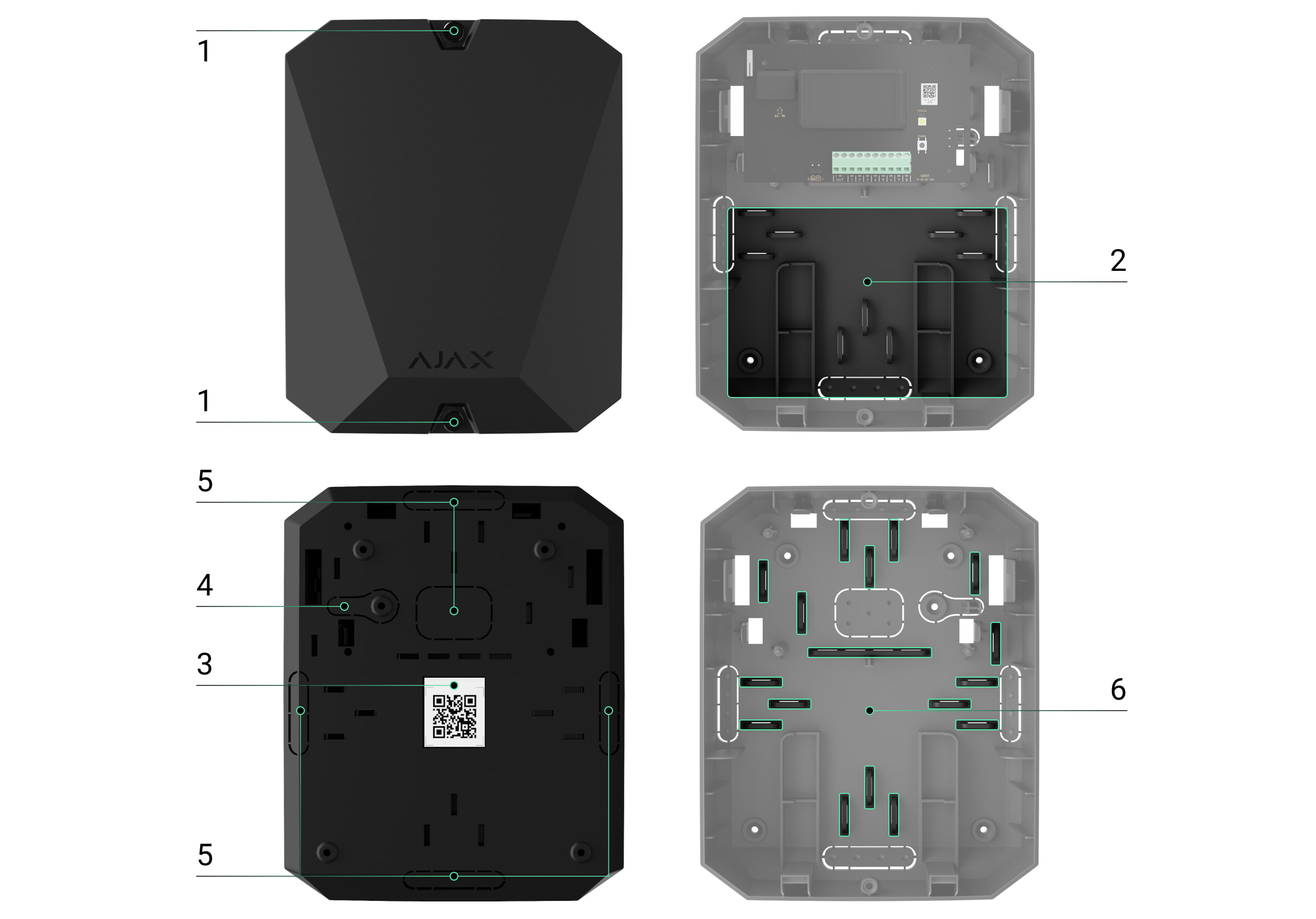
Screws securing the casing lid. Unscrew with a bundled hexagon key (Ø 4 mm).
Space for a 12 V⎓ backup battery.
Battery not included with vhfBridge Jeweller set.
QR code with the device ID. It is used to pair the device with the Ajax security system.
Perforated part of the casing. Necessary for tamper triggering in case of any attempt to detach the device from the surface.
Perforated parts of the casing for cable output.
The presence of the casing depends on the vhfBridge Jeweller package. The device is supplied in two configurations: with a casing and without it.
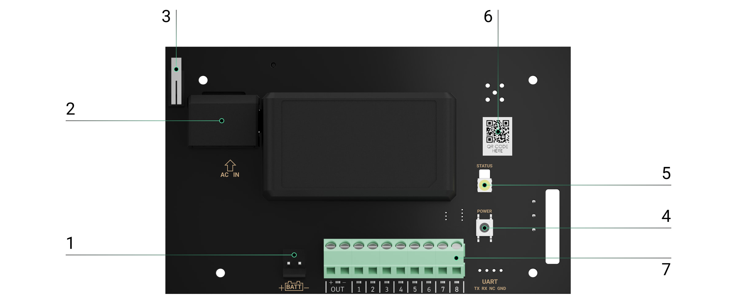
vhfBridge Jeweller board elements
Terminals for connecting a 12 V⎓ backup battery.
100–240 V~ power supply input.
Tamper button. Signals if vhfBridge Jewellercasing lid is removed.
Power button.
LED indicator.
QR code with the device ID. It is used to pair the device with the Ajax security system.
Terminals for connecting a VHF transmitter.
vhfBridge Jeweller terminals
BATT — input for the 12 V⎓ backup power connection.
OUT — power output for the 12 V⎓ VHF transmitter (maximum output current is 2 A).
OUT 1…8 — vhfBridge Jeweller outputs for connecting a VHF transmitter.
LED indication
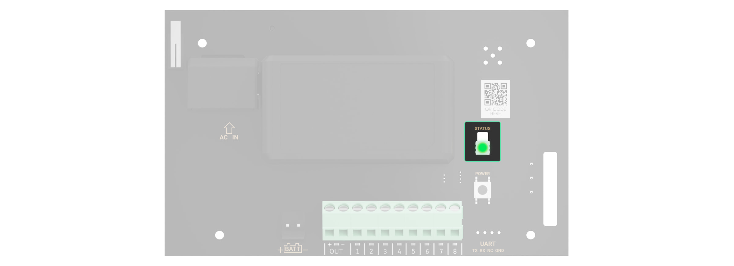
vhfBridge Jeweller LED indicator may light up white, red, or green, depending on the status of the device.
Please note that the LED indicator is not visible when the casing lid is closed. The LED indicator is used at the stage of vhfBridge Jeweller connecting and configuring. Later on, the state of the device can be monitored in the Ajax app.
LED indication
Event
Note
Lights up white.
Connection with the hub is established, external power supply is connected.
Lights up red.
There is no connection with the hub, external power supply is connected.
For example, the hub is turned off or vhfBridge Jeweller is outside the coverage area of the hub’s wireless network.
Goes out for 0.5 seconds, then lights up green and turns off.
Enabling vhfBridge Jeweller.
Goes out for 0.5 seconds, then lights up green and fades out over 3 seconds.
Disabling vhfBridge Jeweller.
Blinks red once per second.
vhfBridge Jeweller is not assigned to a hub.
Lights up for a second once every 10 seconds.
No external power supply is connected to vhfBridge Jeweller.
The colour of the indication depends on the status of connection with the hub:
lights up white if there is connection with the hub;
lights up red if there is no connection with the hub.
During an alarm, gradually lights up and goes out once every 10 seconds.
No external power supply and discharged external battery of vhfBridge Jeweller.
The colour of the indication depends on the status of connection with the hub:
lights up white if there is connection with the hub;
lights up red if there is no connection with the hub.
LED indication of output status
LED indication
Output status in case of alarm
High potential output (positive trip).
Lights up green.
Low potential output (negative trip).
Goes out.
Operating principle
vhfBridge Jeweller is designed to connect third-party VHF transmitters to create an additional channel for transmitting events to the CMS.
The communication channel with the CMS created using vhfBridge Jeweller can be used as the only or as a backup channel for communicating with the CMS (recommended more reliable option). This means that the hub can simultaneously transmit all events and alarms to the monitoring station of the security company not only through SIA (DC-09), ADEMCO 685, SurGard (Contact ID), and other proprietary protocols but also using vhfBridge Jeweller.
The transponder receives information about alarms and events from the hub via the Jeweller radio channel. Then, vhfBridge Jeweller transmits it to a third-party VHF transmitter via wires. The VHF transmitter, in turn, transmits all events and alarms to the CMS via a radio channel.
Events can be transmitted to the CMS via the Internet and vhfBridge Jeweller in parallel. Transmission via the Internet works as the main channel because of greater reliability and informativity. The transmitted events may contain the zone number of the triggered detector, group number, user number, and other data.
vhfBridge Jeweller works as a backup communication channel duplicating all events transmitted via the Internet. The delivery speed of events and alarms in both cases does not exceed 1 second.
An example of the algorithm of actions in case of an alarm from a MotionProtect motion detector:
MotionProtect has detected an alarm.
MotionProtect transmits the alarm to the hub via the Jeweller radio protocol.
The hub receives the MotionProtect alarm and transmits it to vhfBridge Jeweller via the Jeweller radio protocol.
vhfBridge Jeweller receives the alarm from the hub and transmits it to the VHF transmitter over a wired connection.
The VHF transmitter receives the alarm and transmits it to the radio receiver on the CMS side via the radio channel.
The radio receiver receives the alarm and transmits it to the CMS software.
The CMS receives and processes the alarm.
Output types
vhfBridge Jeweller has 8 potential outputs for connection to a VHF transmitter. There are two types of outputs:
High potential output (positive trip).
Low potential output (negative trip).
The high-potential output does not supply voltage in the normal state. As soon as an alarm or event occurs, the output supplies a voltage of 12–14 V⎓. The low-potential output works the other way around. In the normal state, the voltage is maintained at 12–14 V⎓, and when an alarm or event occurs, it drops to 0 V.
The vhfBridge Jeweller output type and alarm pulse duration are configurable in Ajax apps.
VHF transmitter power supply
vhfBridge Jeweller can supply a third-party VHF transmitter with 12 V⎓ power (maximum output current is 2 A).
If the VHF transmitter has a current consumption of more than 2 A, it can be powered by the vhfBridge Jeweller battery. In this case, disable battery charge tracking in the vhfBridge Jeweller settings so that the system users do not receive notifications about the vhfBridge Jeweller battery charging too long.
Sending events to the Central Monitoring Station (CMS)
The Ajax security system can transmit alarms to thePRO Desktopmonitoring app as well as the Central Monitoring Station (CMS) usingSurGard (Contact ID),SIA DC-09 (ADM-CID),ADEMCO 685, and other proprietary protocols. The list of supported protocols isavailable here.
When an alarm is received, the monitoring station operator of the security company knows what happened and where the rapid response unit has to be sent. All Ajax devices are addressable, so events, the device type, its assigned name and room can be transmitted to the PRO Desktop and the CMS. The list of transmitted parameters may differ depending on the type of the CMS and the selected communication protocol.
You can find vhfBridge Jeweller ID and zone number in the Statesin Ajax apps. The device number corresponds to the loop (zone) number.
Adding to the system
vhfBridge Jeweller doesn’t work with Hub, ocBridge Plus, uartBridge and third-party security central units.The device can only be added and configured through the Ajax PRO app by a user with administrator rights.
Open the Ajax app. If your account has access to multiple hubs, select the one to which you want to add vhfBridge Jeweller.
Go to the Devices menu and click Add Device.
Name the transponder, scan or enter the QR code manually (located on the device casing and packaging), and select a room and a group (if the group mode is activated).
Click Add— the countdown will begin.
Switch on vhfBridge Jeweller by holding the power button for 3 seconds. Keep in mind that the hub connection request is only sent when the integration module is turning on.
Please note that to find and pair the device, the transponder should be located within the hub’s radio communication range (on the same secured premises).
If the connection has failed, disconnect vhfBridge Jeweller for 5 seconds and try again. If the transponder has already been assigned to another hub, turn off vhfBridge Jeweller and then follow the standard addition procedure.
The connected transponder will appear in the list of hub devices in the app. Device status updates depend on Jeweller settings. The default status update period in the app is 36 seconds.
Malfunction counter
When a vhfBridge Jeweller malfunction is detected (e.g., no external power), the Ajax app will display a red icon with a number in the upper left corner of the device icon. This number indicates the number of malfunctions.
All malfunctions can be seen in the transponder states. Fields with malfunctions will be highlighted in red.
Icons
Icons display some of the vhfBridge Jeweller states. You can check them in the Ajax app in the Devices tab.
Icon
Meaning
Jeweller Signal Strength. Displays the signal strength between the hub and vhfBridge Jeweller.
Recommended value is 2–3 bars.
The charge level of the battery connected to vhfBridge Jeweller.
The presence of the 100–240 V~ external power supply:
Connected — the external power is connected.
Disconnected — the external power is disconnected.
Name of ReX range extender
Radio signal range extender connection status:
Online — the device is connected.
Offline — the device is not connected.
Please note that the field is displayed if vhfBridge Jeweller is operated via a radio signal range extender.
Permanent Deactivation
Shows the status of the device permanent deactivation function:
No — the device operates in normal mode and transmits all events.
Lid only — the hub admin disabled notifications about tamper alarms.
Entirely — the device is completely excluded from the system operation by the hub admin. The device does not follow system commands and does not report alarms or other events.
Firmware
vhfBridge Jeweller firmware version.
Device ID
vhfBridge Jeweller ID/serial number. Also located on the device box, its board, and the casing.
Device No.
Device loop (zone) number.
vhfBridge Jeweller settings
Settings can be changed in the Ajax app:
Go to the Devices tab.
Select vhfBridge Jeweller from the list.
Go to Settings by clicking the icon in the upper right corner.
Set the parameters.
ClickBackto save the new settings.
Please note that after editing the settings, you should click the Back button to save them.
Configuration
Meaning
Name
vhfBridge Jeweller name. Displayed in the text of SMS and notifications in the event feed.
To change the device name, click on the pencil icon.
The name can contain up to 12 Cyrillic characters or up to 24 Latin characters.
Room
Selecting the virtual room to which vhfBridge Jeweller is assigned.
The room name is displayed in the text of SMS and notifications in the event feed.
Track battery charge time
Set up the battery charge duration.
When this option is enabled, the system will send a malfunction notification if the battery connected to vhfBridge Jeweller has been charging more than 40 hours.
Disable tracking if the VHF transmitter is powered directly from the battery and not from the vhfBridge Jeweller power terminals.
Pulse Duration, sec
Pulse time on an event (from 1 to 255 seconds). Set in increment of 1 second.
The default value is 5 seconds.
Jeweller Signal Strength Test
Switches vhfBridge Jeweller to the Jeweller signal strength test mode.
The test allows you to check the signal strength between the hub and vhfBridge Jeweller and determine the optimal installation location.
Allows the user to disable the device without removing it from the system.
Three options are available:
No — the device operates in normal mode and transmits all events.
Entirely — the device will not execute system commands or participate in automation scenarios, and the system will ignore device alarms and other notifications.
Lid only — the system will ignore notifications about the triggering of the device tamper only.
Opens vhfBridge Jeweller User Guide in the Ajax app.
Unpair Device
Unpairs vhfBridge Jeweller, disconnects it from the hub, and deletes its settings.
vhfBridge Jeweller output configuration
By default, vhfBridge Jeweller outputs are configured as follows:
1st output — intrusion
2nd output — panic button
3rd output — malfunction
4th output — tamper
5th output — loss of vhfBridge Jeweller power supply
6th output — power loss of the hub
7th output — hub battery discharged
8th output — loss of communication between the hub and vhfBridge Jeweller
The settings of outputs can be changed in the Ajax app:
Go to the Devices tab.
Find vhfBridge Jeweller in the list of devices.
Go to the Outputs menu.
Find the output in the list and go to its Settings by clicking the gear icon .
Set the parameters.
Click Back to save the new settings.
Operating mode Selecting the output operating mode:
Pulse— vhfBridge Jeweller generates a pulse of a specified duration when activated.
Bistable— vhfBridge Jeweller changes the state of the contacts to the opposite (e.g., closed to open) when activated. In this mode, contacts will reset their state on disarming or system restore (ifRestoration after alarmis enabled for the same event type as the output).
This setting is available for users with administrator rights or in the PRO app. If the device is connected to hubs with firmware version OS Malevich 2.27 and later.
Configuration
Meaning
Type of Event
Selection of the event type to which vhfBridge Jeweller output reacts.
Check the complete list of event types and their icons below.
Connection type
Selection of the output type:
High potential output (positive trip).
Low potential output (negative trip).
Event types of vhfBridge Jeweller outputs
Icon
Type of event
Operating mode
Description
Not assigned
No
Output disabled.
Intrusion
Pulse
Alarm when motion, opening, and other detectors are triggered.
Fire
Pulse
Alarm when fire detectors are triggered.
Auxiliary alarm
Pulse
Alarm when pressing the auxiliary request alert button.
Confirmed hold-up device alarm according to PD 6662:2017.
Hub-transponder connection loss
Bistable
Loss of vhfBridge Jeweller connection with the hub / radio signal range extender via Jeweller channel.
The time before sending an event regarding the loss of communication between the hub and vhfBridge Jeweller to the CMS is calculated with the following formula:
With the minimum values of the “hub — detector” polling interval, an event regarding the loss of communication with the hub is sent to the CMS in 6 minutes.
Connecting VHF transmitter to vhfBridge Jeweller
List of recommended VHF transmitters
Hawk VHF Alarm Transmitter (FSK Electronics)
TX750C (RDC)
TR-41 (Puper)
vhfBridge Jeweller can be connected to any VHF transmitter with relay inputs. Connection via UART, RS-485, and other interfaces is not supported.
How to connect a VHF transmitter to vhfBridge Jeweller
When connecting the VHF transmitter, do not twist the wires together, but solder them. The ends of the VHF transmitter wires, which will be inserted into the vhfBridge Jeweller terminals should be tinned or crimped with a special sleeve.
Turn off the vhfBridge Jeweller power (if power was connected).
Turn off vhfBridge Jeweller.
Select vhfBridge Jeweller outputs to which you want to connect the VHF transmitter.
Pull the VHF transmitter wires into the vhfBridge Jewellercasingthrough the holes.
There are perforated sections on the casing that can be broken off so that the cable could be pulled through them.
Connect the VHF transmitter to the control outputs of vhfBridge Jeweller according to the wiring diagram in the User Guide supplied by the VHF transmitter manufacturer.
Fasten the cable securely to the vhfBridge Jeweller terminals using a straight screwdriver (slot PL 3.0).
Connect the power to the VHF transmitter.
If a VHF transmitter requires 12 V power to operate, it can be connected to the power terminals of the corresponding vhfBridge Jeweller zone. Do not connect the external power supply to the transmitter power terminals, as this may damage the device.
Connect power to vhfBridge Jeweller.
Turn on vhfBridge Jeweller.
vhfBridge Jeweller functionality testing
Integration module functionality tests do not start immediately but not later than over a single “hub — detector” polling interval (36 seconds with standard hub settings). You can change the polling period of devices in the Jeweller menu of the hub settings.
The placement of vhfBridge Jeweller determines its distance from the hub and the presence of obstacles between them that impede the passage of the radio signal: walls, inter-floor constructions, or large-sized objects located in the room.
Be sure to check the signal strength at the installation site. If the signal strength is low (a single bar), we cannot guarantee a stable operation of the security system. At the very least, relocate the device as repositioning even by 20 cm can significantly improve signal reception.
If poor or unstable signal strength is still reported after the relocation of the device, use the radio signal range extender.
When choosing the installation location, consider the distance between vhfBridge Jeweller and the VHF transmitter: the cable length should be sufficient for connection.
The minimum distance between vhfBridge Jeweller and the radio transmitter is 2 meters and the maximum distance is 7 meters. The minimum distance is required to avoid signal overlapping. The maximum distance allowed will help avoid signal attenuation in the cable.
Material and cross-section of the cable for connecting a VHF transmitter are determined by the manufacturer’s requirements and the maximum current. All requirements can be found in the manual or from the customer service of the VHF transmitter manufacturer.
vhfBridge Jeweller installation
Prior to mounting vhfBridge Jeweller, ensure that you have selected the optimal location corresponding to these instructions.
The transponder casing should be mounted on a vertical surface. If installed on a horizontal surface, thetamperwill not work when somebody attempts to dismantle the transponder.
To install vhfBridge Jeweller:
Remove the vhfBridge Jeweller casing lid by unscrewing the bottom and top screws with the bundled hex wrench.
Remove the vhfBridge Jeweller board from the holders by pulling them to the sides.
Prepare cable openings in advance by carefully breaking out the perforated parts of the casing.
Fasten the casing to a vertical surface at the chosen installation location using the bundled screws. When attaching, use all the fixation points on the casing. One of them, in the perforated part of the mount above the tamper, is needed to trigger the tamper on the back of the board in case of an attempt to tear the casing off the surface.
Run the cables into the transponder casing through the previously made holes.
Install the vhfBridge Jeweller board into the casing on the racks.
Secure the cable with cable ties using special mounts inside the casing.
Install a 12 V⎓ backup battery on the special holders in the casing. Please note that vhfBridge Jeweller cannot be connected to third-party power supply units.
We recommend using a 12 V⎓ battery of 4 or 7 Ah. For such batteries, special holders in the casing are designed. You can also use similar batteries of a different capacity, of the matching size, and with a charging time of no more than 30 hours. The maximum dimensions of the battery to be installed in the casing are 150 × 65 × 94 mm, and the weight is 5 kg.
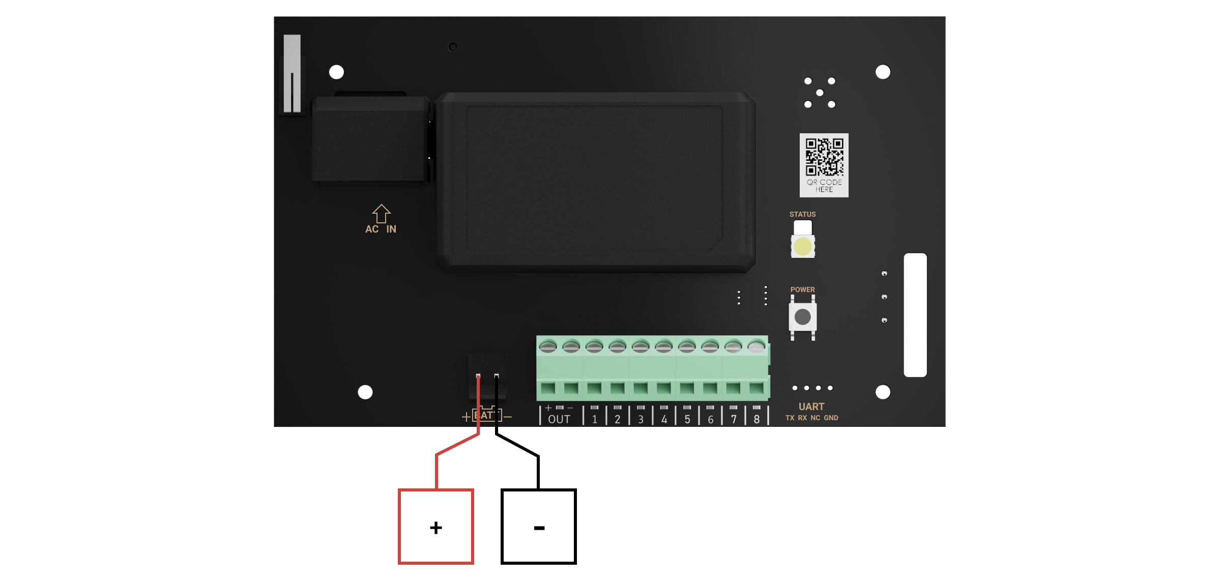
Connect a backup battery to the board terminals according to the wiring diagram below (use the bundled cable). Follow the polarity and connection order of the wires. Securely fasten the conductors to the terminals.
Install the lid on the casing and fix it with the bundled screws.
Test vhfBridge Jeweller and connected VHF transmitter.
Do not install vhfBridge Jeweller
Outdoors. Doing so may cause the device to malfunction or not work properly.
Near metal objects or mirrors (for example, in a metal cabinet). They can shield and attenuate the radio signal.
Inside premises with temperature and humidity outside the permissible limits. Doing so may cause the device to malfunction or not work properly.
At a distance less than 1 meter from the hub or range extender. This could result in the loss of connection with the hub.
At a distance less than 2 meters from the VHF transmitter. The minimum distance is required to avoid signal overlapping
At a distance more than 7 meters from the VHF transmitter. The maximum distance allowed will help avoid signal attenuation in the cable.
Maintenance
Check the functionality of vhfBridge Jeweller regularly. The optimal frequency of checks is once every three months. Clean the casing from dust, cobwebs, and other contaminants as they emerge. Use a soft dry cloth suitable for equipment care. Do not use any substances containing alcohol, acetone, gasoline, and other active solvents to clean the device.
Ajax vhfBridge | VHF radio komunikators, 8 izejas, savienojams ar Hub 2, Hub Plus, Hub 2 Plus | melns
SKU: 367308960
€124,24€158,46
Vienības cena
vhfBridge Jeweller User manual
vhfBridge Jeweller is a module for connecting Ajax security systems to third-party VHF transmitters. It provides 8 transistor outputs for connection to third-party VHF transmitters.
The device is powered from 100–240 V~ mains and can be operated from a 12 V⎓ backup battery.
vhfBridge Jeweller operates as part of the Ajax security system and connects to the hub via the Jeweller secure radio communication protocol. The hub communication range is up to 1,800 meters without obstacles. Supplied in two configurations: with a casing and without it.
Screws securing the casing lid. Unscrew with a bundled hexagon key (Ø 4 mm).
Space for a 12 V⎓ backup battery.
Battery not included with vhfBridge Jeweller set.
QR code with the device ID. It is used to pair the device with the Ajax security system.
Perforated part of the casing. Necessary for tamper triggering in case of any attempt to detach the device from the surface.
Perforated parts of the casing for cable output.
The presence of the casing depends on the vhfBridge Jeweller package. The device is supplied in two configurations: with a casing and without it.
vhfBridge Jeweller board elements
Terminals for connecting a 12 V⎓ backup battery.
100–240 V~ power supply input.
Tamper button. Signals if vhfBridge Jewellercasing lid is removed.
Power button.
LED indicator.
QR code with the device ID. It is used to pair the device with the Ajax security system.
Terminals for connecting a VHF transmitter.
vhfBridge Jeweller terminals
BATT — input for the 12 V⎓ backup power connection.
OUT — power output for the 12 V⎓ VHF transmitter (maximum output current is 2 A).
OUT 1…8 — vhfBridge Jeweller outputs for connecting a VHF transmitter.
LED indication
vhfBridge Jeweller LED indicator may light up white, red, or green, depending on the status of the device.
Please note that the LED indicator is not visible when the casing lid is closed. The LED indicator is used at the stage of vhfBridge Jeweller connecting and configuring. Later on, the state of the device can be monitored in the Ajax app.
LED indication
Event
Note
Lights up white.
Connection with the hub is established, external power supply is connected.
Lights up red.
There is no connection with the hub, external power supply is connected.
For example, the hub is turned off or vhfBridge Jeweller is outside the coverage area of the hub’s wireless network.
Goes out for 0.5 seconds, then lights up green and turns off.
Enabling vhfBridge Jeweller.
Goes out for 0.5 seconds, then lights up green and fades out over 3 seconds.
Disabling vhfBridge Jeweller.
Blinks red once per second.
vhfBridge Jeweller is not assigned to a hub.
Lights up for a second once every 10 seconds.
No external power supply is connected to vhfBridge Jeweller.
The colour of the indication depends on the status of connection with the hub:
lights up white if there is connection with the hub;
lights up red if there is no connection with the hub.
During an alarm, gradually lights up and goes out once every 10 seconds.
No external power supply and discharged external battery of vhfBridge Jeweller.
The colour of the indication depends on the status of connection with the hub:
lights up white if there is connection with the hub;
lights up red if there is no connection with the hub.
LED indication of output status
LED indication
Output status in case of alarm
High potential output (positive trip).
Lights up green.
Low potential output (negative trip).
Goes out.
Operating principle
vhfBridge Jeweller is designed to connect third-party VHF transmitters to create an additional channel for transmitting events to the CMS.
The communication channel with the CMS created using vhfBridge Jeweller can be used as the only or as a backup channel for communicating with the CMS (recommended more reliable option). This means that the hub can simultaneously transmit all events and alarms to the monitoring station of the security company not only through SIA (DC-09), ADEMCO 685, SurGard (Contact ID), and other proprietary protocols but also using vhfBridge Jeweller.
The transponder receives information about alarms and events from the hub via the Jeweller radio channel. Then, vhfBridge Jeweller transmits it to a third-party VHF transmitter via wires. The VHF transmitter, in turn, transmits all events and alarms to the CMS via a radio channel.
Events can be transmitted to the CMS via the Internet and vhfBridge Jeweller in parallel. Transmission via the Internet works as the main channel because of greater reliability and informativity. The transmitted events may contain the zone number of the triggered detector, group number, user number, and other data.
vhfBridge Jeweller works as a backup communication channel duplicating all events transmitted via the Internet. The delivery speed of events and alarms in both cases does not exceed 1 second.
An example of the algorithm of actions in case of an alarm from a MotionProtect motion detector:
MotionProtect has detected an alarm.
MotionProtect transmits the alarm to the hub via the Jeweller radio protocol.
The hub receives the MotionProtect alarm and transmits it to vhfBridge Jeweller via the Jeweller radio protocol.
vhfBridge Jeweller receives the alarm from the hub and transmits it to the VHF transmitter over a wired connection.
The VHF transmitter receives the alarm and transmits it to the radio receiver on the CMS side via the radio channel.
The radio receiver receives the alarm and transmits it to the CMS software.
The CMS receives and processes the alarm.
Output types
vhfBridge Jeweller has 8 potential outputs for connection to a VHF transmitter. There are two types of outputs:
High potential output (positive trip).
Low potential output (negative trip).
The high-potential output does not supply voltage in the normal state. As soon as an alarm or event occurs, the output supplies a voltage of 12–14 V⎓. The low-potential output works the other way around. In the normal state, the voltage is maintained at 12–14 V⎓, and when an alarm or event occurs, it drops to 0 V.
The vhfBridge Jeweller output type and alarm pulse duration are configurable in Ajax apps.
VHF transmitter power supply
vhfBridge Jeweller can supply a third-party VHF transmitter with 12 V⎓ power (maximum output current is 2 A).
If the VHF transmitter has a current consumption of more than 2 A, it can be powered by the vhfBridge Jeweller battery. In this case, disable battery charge tracking in the vhfBridge Jeweller settings so that the system users do not receive notifications about the vhfBridge Jeweller battery charging too long.
Sending events to the Central Monitoring Station (CMS)
The Ajax security system can transmit alarms to thePRO Desktopmonitoring app as well as the Central Monitoring Station (CMS) usingSurGard (Contact ID),SIA DC-09 (ADM-CID),ADEMCO 685, and other proprietary protocols. The list of supported protocols isavailable here.
When an alarm is received, the monitoring station operator of the security company knows what happened and where the rapid response unit has to be sent. All Ajax devices are addressable, so events, the device type, its assigned name and room can be transmitted to the PRO Desktop and the CMS. The list of transmitted parameters may differ depending on the type of the CMS and the selected communication protocol.
You can find vhfBridge Jeweller ID and zone number in the Statesin Ajax apps. The device number corresponds to the loop (zone) number.
Adding to the system
vhfBridge Jeweller doesn’t work with Hub, ocBridge Plus, uartBridge and third-party security central units.The device can only be added and configured through the Ajax PRO app by a user with administrator rights.
Open the Ajax app. If your account has access to multiple hubs, select the one to which you want to add vhfBridge Jeweller.
Go to the Devices menu and click Add Device.
Name the transponder, scan or enter the QR code manually (located on the device casing and packaging), and select a room and a group (if the group mode is activated).
Click Add— the countdown will begin.
Switch on vhfBridge Jeweller by holding the power button for 3 seconds. Keep in mind that the hub connection request is only sent when the integration module is turning on.
Please note that to find and pair the device, the transponder should be located within the hub’s radio communication range (on the same secured premises).
If the connection has failed, disconnect vhfBridge Jeweller for 5 seconds and try again. If the transponder has already been assigned to another hub, turn off vhfBridge Jeweller and then follow the standard addition procedure.
The connected transponder will appear in the list of hub devices in the app. Device status updates depend on Jeweller settings. The default status update period in the app is 36 seconds.
Malfunction counter
When a vhfBridge Jeweller malfunction is detected (e.g., no external power), the Ajax app will display a red icon with a number in the upper left corner of the device icon. This number indicates the number of malfunctions.
All malfunctions can be seen in the transponder states. Fields with malfunctions will be highlighted in red.
Icons
Icons display some of the vhfBridge Jeweller states. You can check them in the Ajax app in the Devices tab.
Icon
Meaning
Jeweller Signal Strength. Displays the signal strength between the hub and vhfBridge Jeweller.
Recommended value is 2–3 bars.
The charge level of the battery connected to vhfBridge Jeweller.
The presence of the 100–240 V~ external power supply:
Connected — the external power is connected.
Disconnected — the external power is disconnected.
Name of ReX range extender
Radio signal range extender connection status:
Online — the device is connected.
Offline — the device is not connected.
Please note that the field is displayed if vhfBridge Jeweller is operated via a radio signal range extender.
Permanent Deactivation
Shows the status of the device permanent deactivation function:
No — the device operates in normal mode and transmits all events.
Lid only — the hub admin disabled notifications about tamper alarms.
Entirely — the device is completely excluded from the system operation by the hub admin. The device does not follow system commands and does not report alarms or other events.
Firmware
vhfBridge Jeweller firmware version.
Device ID
vhfBridge Jeweller ID/serial number. Also located on the device box, its board, and the casing.
Device No.
Device loop (zone) number.
vhfBridge Jeweller settings
Settings can be changed in the Ajax app:
Go to the Devices tab.
Select vhfBridge Jeweller from the list.
Go to Settings by clicking the icon in the upper right corner.
Set the parameters.
ClickBackto save the new settings.
Please note that after editing the settings, you should click the Back button to save them.
Configuration
Meaning
Name
vhfBridge Jeweller name. Displayed in the text of SMS and notifications in the event feed.
To change the device name, click on the pencil icon.
The name can contain up to 12 Cyrillic characters or up to 24 Latin characters.
Room
Selecting the virtual room to which vhfBridge Jeweller is assigned.
The room name is displayed in the text of SMS and notifications in the event feed.
Track battery charge time
Set up the battery charge duration.
When this option is enabled, the system will send a malfunction notification if the battery connected to vhfBridge Jeweller has been charging more than 40 hours.
Disable tracking if the VHF transmitter is powered directly from the battery and not from the vhfBridge Jeweller power terminals.
Pulse Duration, sec
Pulse time on an event (from 1 to 255 seconds). Set in increment of 1 second.
The default value is 5 seconds.
Jeweller Signal Strength Test
Switches vhfBridge Jeweller to the Jeweller signal strength test mode.
The test allows you to check the signal strength between the hub and vhfBridge Jeweller and determine the optimal installation location.
Allows the user to disable the device without removing it from the system.
Three options are available:
No — the device operates in normal mode and transmits all events.
Entirely — the device will not execute system commands or participate in automation scenarios, and the system will ignore device alarms and other notifications.
Lid only — the system will ignore notifications about the triggering of the device tamper only.
Opens vhfBridge Jeweller User Guide in the Ajax app.
Unpair Device
Unpairs vhfBridge Jeweller, disconnects it from the hub, and deletes its settings.
vhfBridge Jeweller output configuration
By default, vhfBridge Jeweller outputs are configured as follows:
1st output — intrusion
2nd output — panic button
3rd output — malfunction
4th output — tamper
5th output — loss of vhfBridge Jeweller power supply
6th output — power loss of the hub
7th output — hub battery discharged
8th output — loss of communication between the hub and vhfBridge Jeweller
The settings of outputs can be changed in the Ajax app:
Go to the Devices tab.
Find vhfBridge Jeweller in the list of devices.
Go to the Outputs menu.
Find the output in the list and go to its Settings by clicking the gear icon .
Set the parameters.
Click Back to save the new settings.
Operating mode Selecting the output operating mode:
Pulse— vhfBridge Jeweller generates a pulse of a specified duration when activated.
Bistable— vhfBridge Jeweller changes the state of the contacts to the opposite (e.g., closed to open) when activated. In this mode, contacts will reset their state on disarming or system restore (ifRestoration after alarmis enabled for the same event type as the output).
This setting is available for users with administrator rights or in the PRO app. If the device is connected to hubs with firmware version OS Malevich 2.27 and later.
Configuration
Meaning
Type of Event
Selection of the event type to which vhfBridge Jeweller output reacts.
Check the complete list of event types and their icons below.
Connection type
Selection of the output type:
High potential output (positive trip).
Low potential output (negative trip).
Event types of vhfBridge Jeweller outputs
Icon
Type of event
Operating mode
Description
Not assigned
No
Output disabled.
Intrusion
Pulse
Alarm when motion, opening, and other detectors are triggered.
Fire
Pulse
Alarm when fire detectors are triggered.
Auxiliary alarm
Pulse
Alarm when pressing the auxiliary request alert button.
Confirmed hold-up device alarm according to PD 6662:2017.
Hub-transponder connection loss
Bistable
Loss of vhfBridge Jeweller connection with the hub / radio signal range extender via Jeweller channel.
The time before sending an event regarding the loss of communication between the hub and vhfBridge Jeweller to the CMS is calculated with the following formula:
With the minimum values of the “hub — detector” polling interval, an event regarding the loss of communication with the hub is sent to the CMS in 6 minutes.
Connecting VHF transmitter to vhfBridge Jeweller
List of recommended VHF transmitters
Hawk VHF Alarm Transmitter (FSK Electronics)
TX750C (RDC)
TR-41 (Puper)
vhfBridge Jeweller can be connected to any VHF transmitter with relay inputs. Connection via UART, RS-485, and other interfaces is not supported.
How to connect a VHF transmitter to vhfBridge Jeweller
When connecting the VHF transmitter, do not twist the wires together, but solder them. The ends of the VHF transmitter wires, which will be inserted into the vhfBridge Jeweller terminals should be tinned or crimped with a special sleeve.
Turn off the vhfBridge Jeweller power (if power was connected).
Turn off vhfBridge Jeweller.
Select vhfBridge Jeweller outputs to which you want to connect the VHF transmitter.
Pull the VHF transmitter wires into the vhfBridge Jewellercasingthrough the holes.
There are perforated sections on the casing that can be broken off so that the cable could be pulled through them.
Connect the VHF transmitter to the control outputs of vhfBridge Jeweller according to the wiring diagram in the User Guide supplied by the VHF transmitter manufacturer.
Fasten the cable securely to the vhfBridge Jeweller terminals using a straight screwdriver (slot PL 3.0).
Connect the power to the VHF transmitter.
If a VHF transmitter requires 12 V power to operate, it can be connected to the power terminals of the corresponding vhfBridge Jeweller zone. Do not connect the external power supply to the transmitter power terminals, as this may damage the device.
Connect power to vhfBridge Jeweller.
Turn on vhfBridge Jeweller.
vhfBridge Jeweller functionality testing
Integration module functionality tests do not start immediately but not later than over a single “hub — detector” polling interval (36 seconds with standard hub settings). You can change the polling period of devices in the Jeweller menu of the hub settings.
The placement of vhfBridge Jeweller determines its distance from the hub and the presence of obstacles between them that impede the passage of the radio signal: walls, inter-floor constructions, or large-sized objects located in the room.
Be sure to check the signal strength at the installation site. If the signal strength is low (a single bar), we cannot guarantee a stable operation of the security system. At the very least, relocate the device as repositioning even by 20 cm can significantly improve signal reception.
If poor or unstable signal strength is still reported after the relocation of the device, use the radio signal range extender.
When choosing the installation location, consider the distance between vhfBridge Jeweller and the VHF transmitter: the cable length should be sufficient for connection.
The minimum distance between vhfBridge Jeweller and the radio transmitter is 2 meters and the maximum distance is 7 meters. The minimum distance is required to avoid signal overlapping. The maximum distance allowed will help avoid signal attenuation in the cable.
Material and cross-section of the cable for connecting a VHF transmitter are determined by the manufacturer’s requirements and the maximum current. All requirements can be found in the manual or from the customer service of the VHF transmitter manufacturer.
vhfBridge Jeweller installation
Prior to mounting vhfBridge Jeweller, ensure that you have selected the optimal location corresponding to these instructions.
The transponder casing should be mounted on a vertical surface. If installed on a horizontal surface, thetamperwill not work when somebody attempts to dismantle the transponder.
To install vhfBridge Jeweller:
Remove the vhfBridge Jeweller casing lid by unscrewing the bottom and top screws with the bundled hex wrench.
Remove the vhfBridge Jeweller board from the holders by pulling them to the sides.
Prepare cable openings in advance by carefully breaking out the perforated parts of the casing.
Fasten the casing to a vertical surface at the chosen installation location using the bundled screws. When attaching, use all the fixation points on the casing. One of them, in the perforated part of the mount above the tamper, is needed to trigger the tamper on the back of the board in case of an attempt to tear the casing off the surface.
Run the cables into the transponder casing through the previously made holes.
Install the vhfBridge Jeweller board into the casing on the racks.
Secure the cable with cable ties using special mounts inside the casing.
Install a 12 V⎓ backup battery on the special holders in the casing. Please note that vhfBridge Jeweller cannot be connected to third-party power supply units.
We recommend using a 12 V⎓ battery of 4 or 7 Ah. For such batteries, special holders in the casing are designed. You can also use similar batteries of a different capacity, of the matching size, and with a charging time of no more than 30 hours. The maximum dimensions of the battery to be installed in the casing are 150 × 65 × 94 mm, and the weight is 5 kg.
Connect a backup battery to the board terminals according to the wiring diagram below (use the bundled cable). Follow the polarity and connection order of the wires. Securely fasten the conductors to the terminals.
Install the lid on the casing and fix it with the bundled screws.
Test vhfBridge Jeweller and connected VHF transmitter.
Do not install vhfBridge Jeweller
Outdoors. Doing so may cause the device to malfunction or not work properly.
Near metal objects or mirrors (for example, in a metal cabinet). They can shield and attenuate the radio signal.
Inside premises with temperature and humidity outside the permissible limits. Doing so may cause the device to malfunction or not work properly.
At a distance less than 1 meter from the hub or range extender. This could result in the loss of connection with the hub.
At a distance less than 2 meters from the VHF transmitter. The minimum distance is required to avoid signal overlapping
At a distance more than 7 meters from the VHF transmitter. The maximum distance allowed will help avoid signal attenuation in the cable.
Maintenance
Check the functionality of vhfBridge Jeweller regularly. The optimal frequency of checks is once every three months. Clean the casing from dust, cobwebs, and other contaminants as they emerge. Use a soft dry cloth suitable for equipment care. Do not use any substances containing alcohol, acetone, gasoline, and other active solvents to clean the device.
{"id":55844753211727,"title":"Default Title","option1":"Default Title","option2":null,"option3":null,"sku":"External Antenna black","requires_shipping":true,"taxable":true,"featured_image":null,"available":true,"name":"Ajax antena | LTE vai radio sakariem, SMA savienotājs, vads līdz 3 m, līmējams stiprinājums","public_title":null,"options":["Default Title"],"price":2181,"weight":0,"compare_at_price":2781,"inventory_management":"shopify","barcode":null,"requires_selling_plan":false,"selling_plan_allocations":[],"quantity_rule":{"min":1,"max":null,"increment":1}}
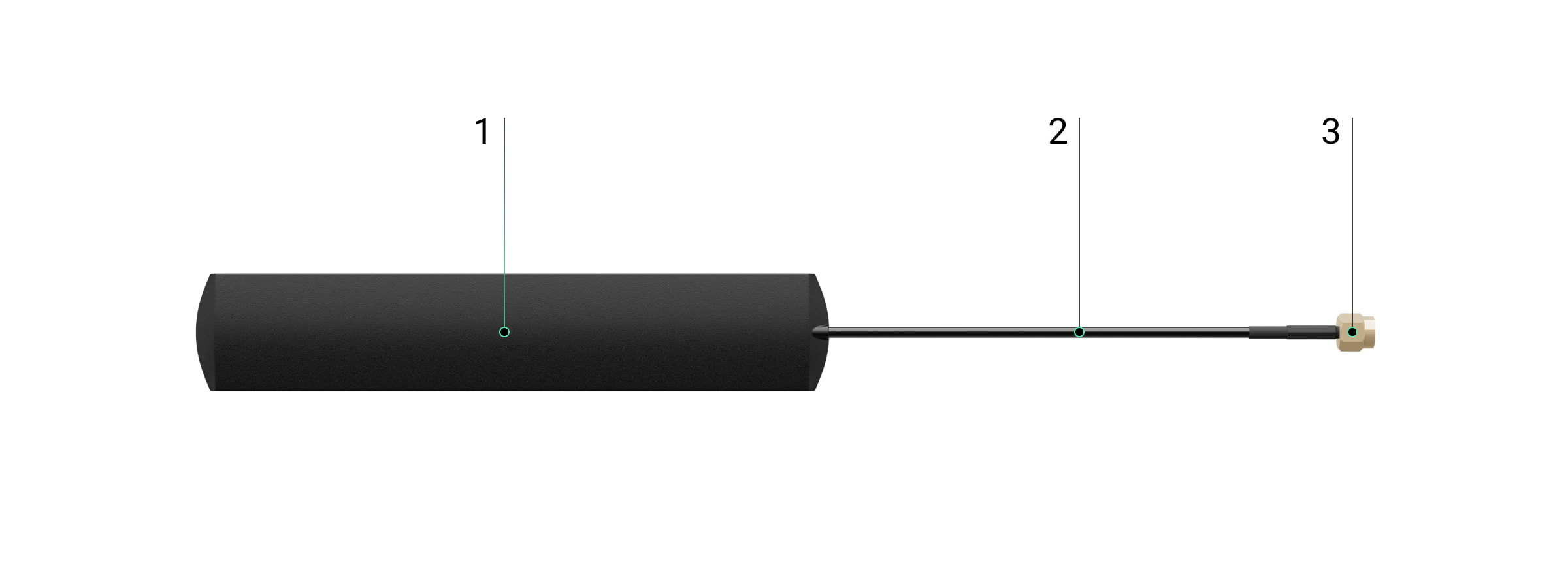
Antena. Koaksiālais kabelis. SMA savienotājs (vīriešu).
Saderīgie hubi
Lai antena darbotos, nepieciešams saderīgs Ajax hub.
Ierīce ir saderīga ar:
Hub BP Jeweller
ExternalAntenna tiek pārdota atsevišķi.
Darbības princips
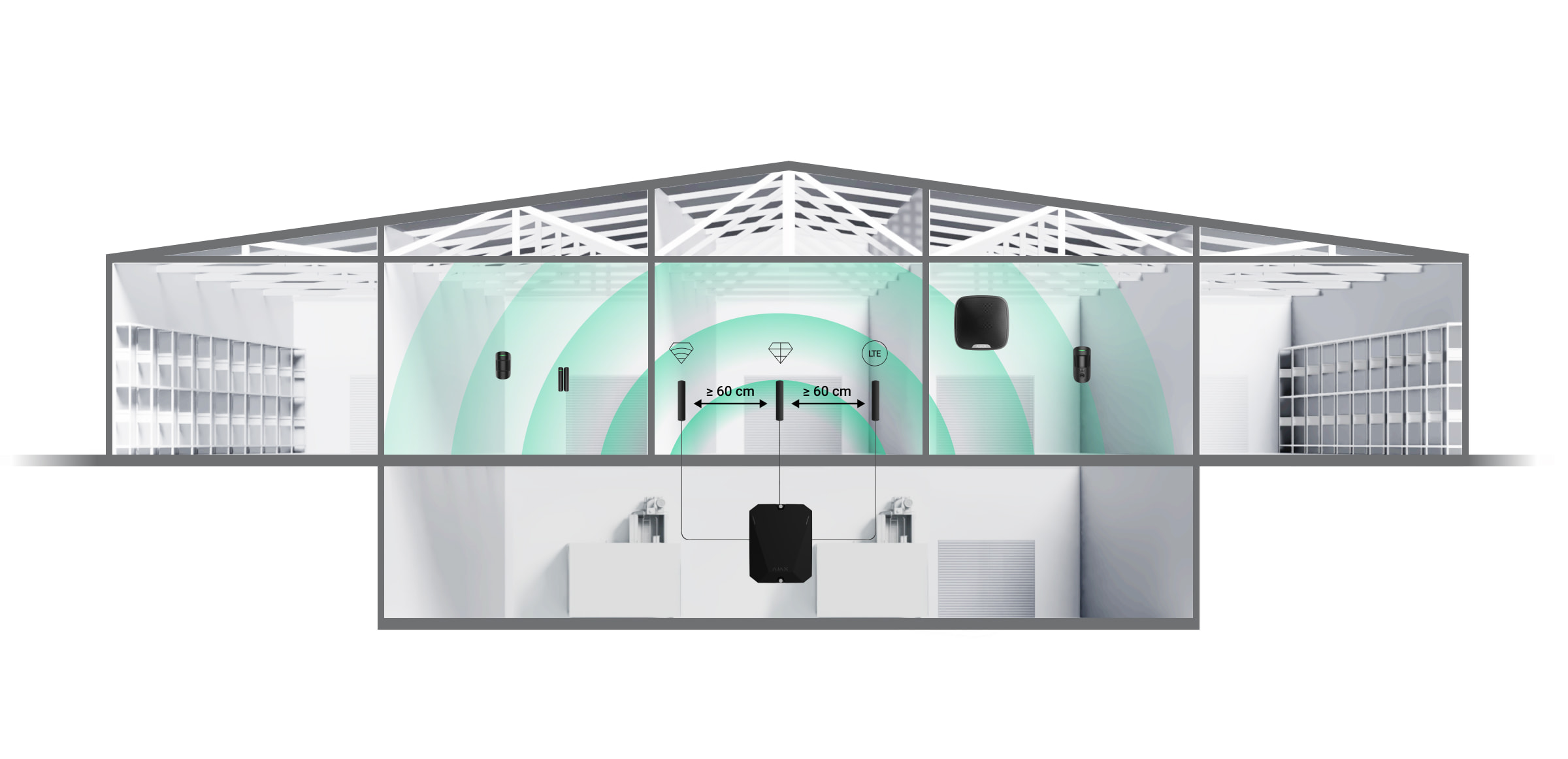
ExternalAntenna uzlabo sakarus starp hubu un pievienotajām ierīcēm vai mobilo tīklu. Tā ir noderīga, ja hubs tiek uzstādīts seifā, dzelzsbetona telpā vai citās vietās, kur signālam jāpārvar šķēršļi. Antenu var pievienot nepieciešamajiem Jeweller, Wings vai Cellular savienotājiem.
Uzstādīšanas vietas izvēle
Izvēloties antenas uzstādīšanas vietu, jāņem vērā faktori, kas ietekmē tās darbību:
Izvēlētā sakaru kanāla signāla stiprums (Jeweller, Wings vai Cellular).
Attālums starp antenu un hubu. Izmantojot divas vai vairākas antenas, attālumam starp tām jābūt vismaz 60 cm.
Šķēršļi, kas ietekmē radio signālu: sienas, starpstāvu pārsegumi un telpā esoši lieli priekšmeti.
Izstrādājot Ajax sistēmu, ievērojiet uzstādīšanas ieteikumus. Drošības sistēmu drīkst projektēt un uzstādīt tikai speciālisti. Ieteikto Ajax partneru saraksts pieejams šeit.
Vietas, kur antenu nedrīkst uzstādīt
Telpās, kur temperatūra un mitrums pārsniedz pieļaujamos limitus. Tas var sabojāt antenu.
Vietās ar zemu signāla līmeni. Tas var izraisīt savienojuma zudumu.
Tuvu metāla priekšmetiem un spoguļiem. Vadītspējīgi priekšmeti var aizsegt antenu.
Sagatavošanās uzstādīšanai
Pirms ārējās antenas uzstādīšanas pārliecinieties, ka:
hubs ir saderīgs ar ExternalAntenna;
hubam uzstādīšanas vietā ir stabils 2–3 stabiņu signāls ar mobilo tīklu;
uzstādīšanas vietā visām pievienotajām ierīcēm ir stabils 2–3 stabiņu signāls;
kabeļa garums no huba līdz uzstādīšanas vietai ir pietiekams.
Kabeļu izvietojums
Sagatavojot kabeļu maršrutēšanu, pārbaudiet sava reģiona elektroinstalācijas un ugunsdrošības noteikumus. Stingri ievērojiet šos standartus un noteikumus. Praktiski ieteikumi par kabeļu izvietojumu ir pieejami šajā rakstā.
Kabeļu maršrutēšana
Pirms uzstādīšanas rūpīgi izlasiet sadaļu Uzstādīšanas vietas izvēle. Izvairieties no novirzēm no sistēmas projekta. Pamatnoteikumu un šīs rokasgrāmatas ieteikumu neievērošana var radīt ierīces darbības traucējumus. Uzzināt vairāk
Uzstādīšana
Pirms uzstādīšanas pārliecinieties, ka esat izvēlējies optimālo ierīces vietu, kas atbilst šīs rokasgrāmatas prasībām.
Ierīci drīkst uzstādīt tikai profesionāls elektriķis.
Kā uzstādīt ExternalAntenna
Pirms antenas uzstādīšanas izlasiet attiecīgā huba rokasgrāmatu.
Pirms uzstādīšanas pārliecinieties, ka hubs ir atslēgts no strāvas.
Noņemiet huba priekšējo vāku.
Identificējiet Jeweller, Wings vai Cellular savienotājus uz plates.
Noņemiet izolācijas vāciņu no izvēlētā savienotāja.
Pievienojiet antenas SMA (vīriešu) savienotāju pie plates SMA (sieviešu) savienotāja.
Ieslēdziet hubu. Aizveriet huba korpusu. Noņemiet aizsargplēvi no iepriekš uzklātās divpusējās līmlentes. Uzstādiet antenu izvēlētajā vietā. Pārbaudiet savienojuma statusu lietotnē.
Statusi
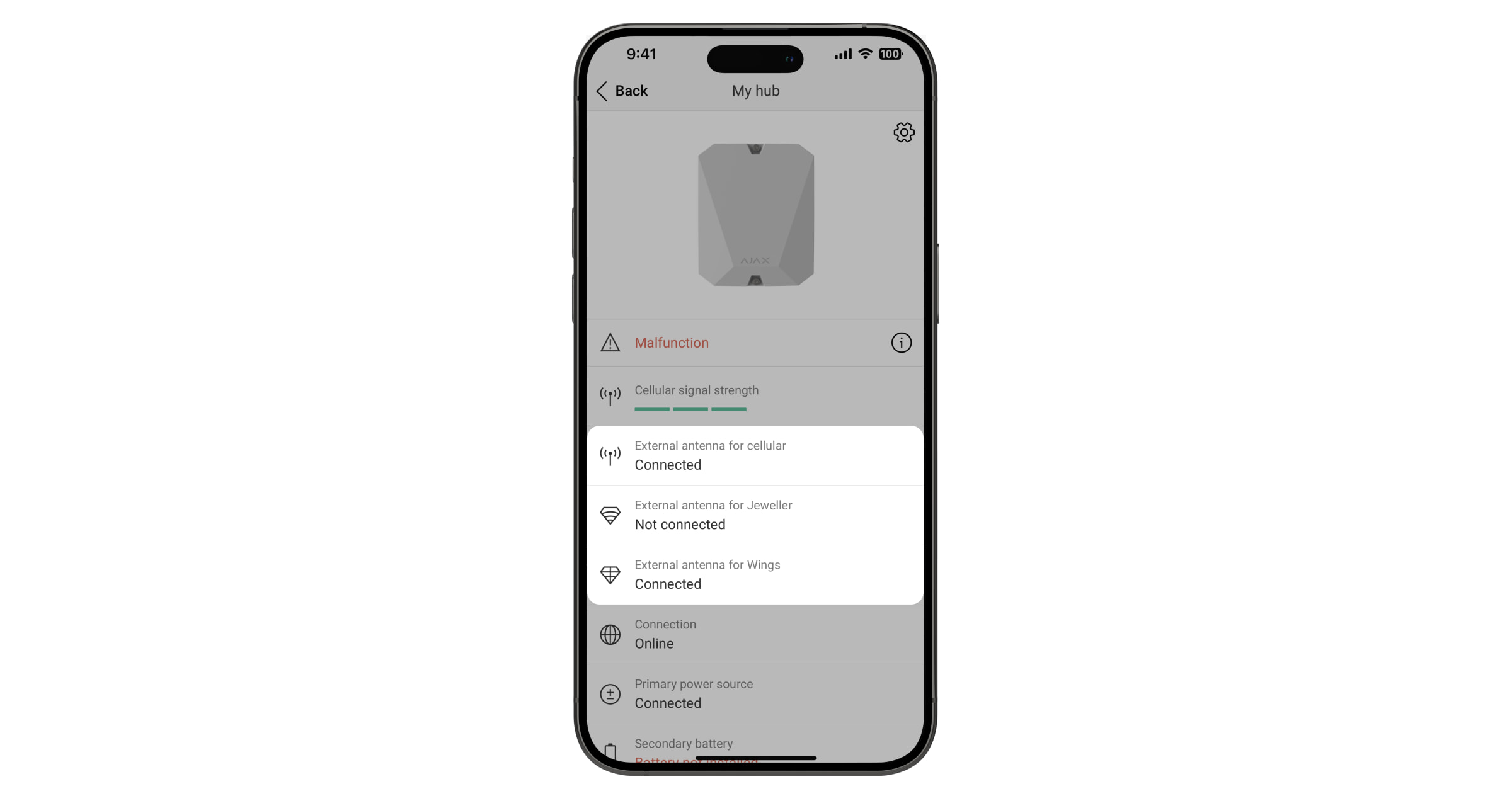
Huba statusos ir informācija par antenas savienojuma stāvokli. Šie statusi ir pieejami Ajax lietotnē:
Atveriet cilni Ierīces.
Sarakstā izvēlieties hubu.
Ja ExternalAntenna tiek bojāta, sistēma paziņos par to lietotājam un CMS.
Apkope
ExternalAntenna neprasa apkopi.
Tehniskās specifikācijas Visas tehniskās specifikācijas
Atbilstība standartiem
Garantija
Sabiedrības ar ierobežotu atbildību “Ajax Systems Manufacturing” produktu garantija ir derīga 2 gadus pēc iegādes.
Ja ierīce nedarbojas pareizi, vispirms sazinieties ar Ajax tehnisko atbalstu. Vairumā gadījumu tehniskas problēmas var atrisināt attālināti.